2014 NISSAN TEANA transmission
[x] Cancel search: transmissionPage 2541 of 4801

ABBREVIATIONSGI-13
< HOW TO USE THIS MANUAL >
C
D E
F
G H
I
J
K L
M B
GI
N
O PABBREVIATIONS
Abbreviation ListINFOID:0000000009462979
The following ABBREVIATIONS are used:
A
B
C
D
ABBREVIATION DESCRIPTION A/C Air conditioner
A/C Air conditioning
A/F sensor Air fuel ratio sensor A/T Automatic transaxle/transmission
ABS Anti-lock braking system
ACCS Advance climate control system ACL Air cleaner
AP Accelerator pedal
APP Accelerator pedal position AV Audio visual
AVM Around view monitor
AWD All wheel drive
ABBREVIATION DESCRIPTION BARO Barometric pressureBCI Backup collision intervention
BCM Body control module
BLSD Brake limited slip differential BPP Brake pedal positionBSI Blind spot intervention
BSW Blind spot warning
ABBREVIATION DESCRIPTION CKP Crankshaft positionCL Closed loop
CMP Camshaft position CPP Clutch pedal positionCTP Closed throttle position
CVT Continuously variable transaxle/transmission
ABBREVIATION DESCRIPTION D
1Drive range first gear
D
2Drive range second gear
D
3Drive range third gear
D
4Drive range fourth gear
DCA Distance control assist
DDS Downhill drive support DFI Direct fuel injection system
DLC Data link connector
DTC Diagnostic trouble code
Revision: November 20132014 Altima NAMRevision: November 20132014 Altima NAM
Page 2543 of 4801

ABBREVIATIONSGI-15
< HOW TO USE THIS MANUAL >
C
D E
F
G H
I
J
K L
M B
GI
N
O P
I
K
L
M
N
O
ABBREVIATION DESCRIPTION I/M Inspection and maintenanceIA Intake air
IAC Idle air control IAT Intake air temperature
IBA Intelligent brake assist IC Ignition control
ICC Intelligent cruise control
ICM Ignition control module
IPDM E/R Intelligent power distribution module engine room ISC Idle speed controlISS Input shaft speed ITS Information technology suite
ABBREVIATION DESCRIPTION KS Knock sensor
ABBREVIATION DESCRIPTION LBC Li-ion battery controller
LCD Liquid crystal display
LCU Local control unit LDP Lane departure prevention
LDW Lane departure warning LED Light emitting diode LH Left-hand
LIN Local interconnect network
ABBREVIATION DESCRIPTION M/T Manual transaxle/transmission
MAF Mass airflow
MAP Manifold absolute pressure
MDU Multi display unit MI Malfunction indicator
MIL Malfunction indicator lamp
MOD Moving object detection
ABBREVIATION DESCRIPTION NOX Nitrogen oxides
ABBREVIATION DESCRIPTION O2 Oxygen
O2S Oxygen sensor
OBD On board diagnostic OC Oxidation catalytic converter
OD Overdrive
Revision: November 20132014 Altima NAMRevision: November 20132014 Altima NAM
Page 2544 of 4801

GI-16
< HOW TO USE THIS MANUAL >
ABBREVIATIONS
P
R
S
T
U
V
OL Open loop
OSS Output shaft speed
ABBREVIATION DESCRIPTION P/S Power steering
PBR Potentio balance resistor
PCV Positive crankcase ventilation
PNP Park/Neutral position PSP Power steering pressurePTC Positive temperature coefficient
PTO Power takeoff
PWM Pulse width modulation
ABBREVIATION DESCRIPTION RAM Random access memoryRAS Rear active steer RH Right-hand
ROM Read only memory RPM Engine speed RR Rear
ABBREVIATION DESCRIPTION SAE Society of Automotive Engineers, Inc.
SCK Serial clock
SDS Service Data and Specifications SRT System readiness testSST Special Service Tools
ABBREVIATION DESCRIPTION TC Turbocharger
TCM Transmission control module TCS Traction control system
TCU Telematics communication unit TP Throttle position
TPMS Tire pressure monitoring system TSS Turbine shaft speed
TWC Three way catalytic converter
ABBREVIATION DESCRIPTION USS Uphill start support
ABBREVIATION DESCRIPTION VCM Vehicle control moduleVDC Vehicle dynamics control system
ABBREVIATION DESCRIPTION
Revision: November 20132014 Altima NAMRevision: November 20132014 Altima NAM
Page 2550 of 4801

GI-22
< VEHICLE INFORMATION >
IDENTIFICATION INFORMATION
VEHICLE INFORMATION
IDENTIFICATION INFORMATION
Model VariationINFOID:0000000009462984
Prefix and suffix designations:
Engine Grade TransmissionDestination
50-State California Canada
QR25DE 2.5 CVT BDBALPZ-EUA BDBALPZ-EVA BDBALPZ-ENA
2.5 S CVT BDBALRZ-EUA BDBALRZ-EVA BDBALRZ-ENA
2.5 SV CVT BDBALUZ-EUA BDBALUZ-EVA BDBALUZ-ENA
CVT BDBALTZ-EUA BDBALTZ-EVA —
2.5 SL CVT BDBALXZ-EUA BDBALXZ-EVA BDBALVZ-ENA
VQ35DE 3.5 S CVT BLJALRW-EUA — —
3.5 SV CVT BLJALTW-EUA — BLJALRW-ENA 3.5 SL CVT BLJALVW-EUA — BLJALVW-ENA
Position Character Qualifier Definition 1 B Body type B: Sedan
2 DB Engine DB: QR25DE
3LJ: VQ35DE
4AAxle A: 2WD
5LDrive L: LH
6PGrade P: 2.5 (USA and CAN)
R: S (USA), 3.5 SV (CAN)
T: 2.5 SV [with convenience package (USA)], 3.5 SV (USA)
U: 2.5 SV [USA (without convenience package) and CAN]
V: 3.5 SL (USA and CAN)
X: 2.5 SL (USA)
7 W Transmission W: CVT (VQ35DE)
Z: CVT (QR25DE)
8 L33 Model L33: Altima
9
10 11 E I n t a k e E : E G I
12 U Zone N: Canada
U: 50-State
V: California
13 A Equipment A: Standard
14
XXXXX Option Codes Option Codes
15
16
17
18
Revision: November 20132014 Altima NAMRevision: November 20132014 Altima NAM
Page 2555 of 4801

PRECAUTIONSGI-27
< PRECAUTION >
C
D E
F
G H
I
J
K L
M B
GI
N
O P
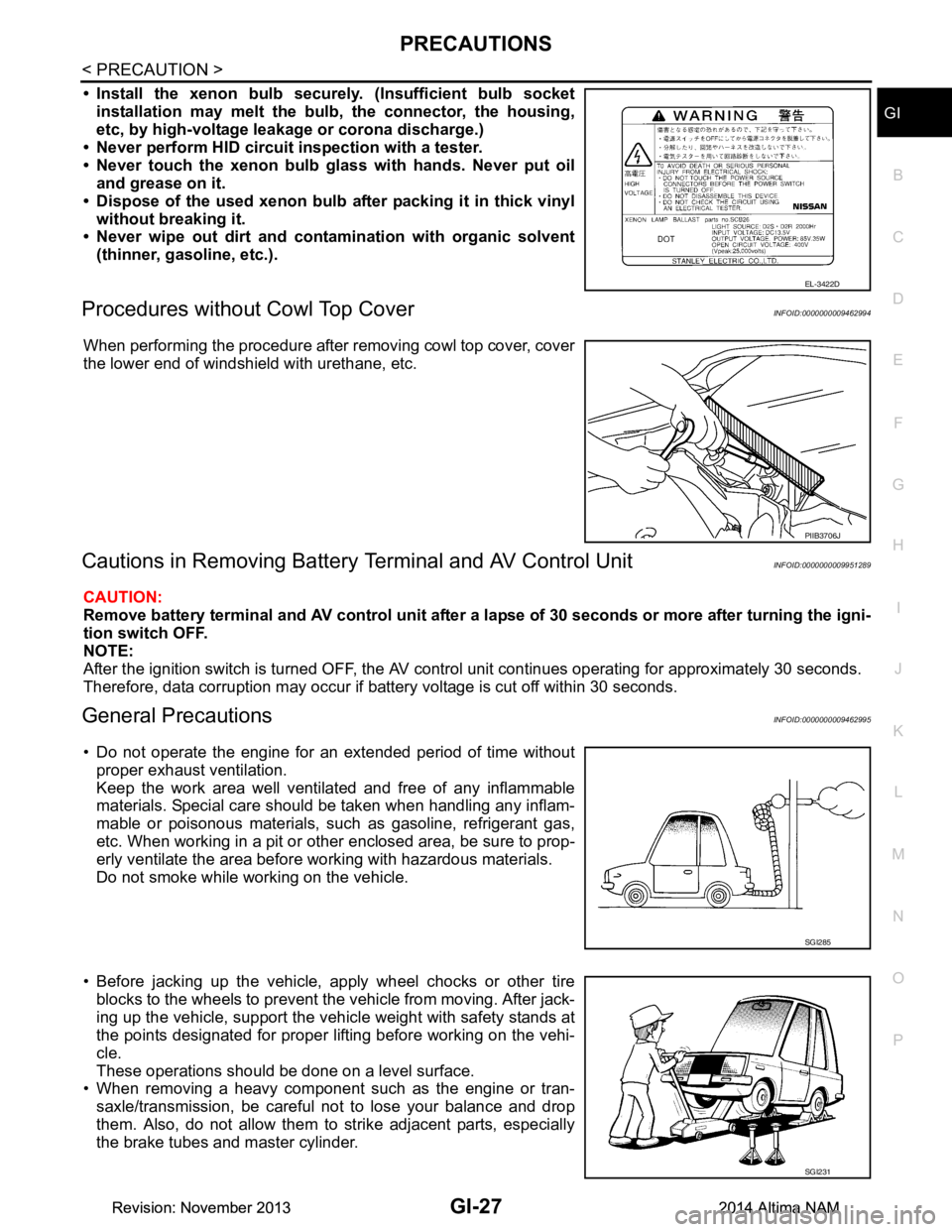
• Install the xenon bulb secure ly. (Insufficient bulb socket
installation may melt the bu lb, the connector, the housing,
etc, by high-voltage leakage or corona discharge.)
• Never perform HID circuit inspection with a tester.
• Never touch the xenon bulb gl ass with hands. Never put oil
and grease on it.
• Dispose of the used xenon bulb after packing it in thick vinyl
without breaking it.
• Never wipe out dirt and contam ination with organic solvent
(thinner, gasoline, etc.).
Procedures without Cowl Top CoverINFOID:0000000009462994
When performing the procedure after removing cowl top cover, cover
the lower end of windshield with urethane, etc.
Cautions in Removing Battery Terminal and AV Control UnitINFOID:0000000009951289
CAUTION:
Remove battery terminal and AV control unit after a lapse of 30 seconds or more after turning the igni-
tion switch OFF.
NOTE:
After the ignition switch is turned OFF, the AV cont rol unit continues operating for approximately 30 seconds.
Therefore, data corruption may occur if battery voltage is cut off within 30 seconds.
General PrecautionsINFOID:0000000009462995
• Do not operate the engine for an extended period of time without proper exhaust ventilation.
Keep the work area well ventilated and free of any inflammable
materials. Special care should be taken when handling any inflam-
mable or poisonous materials, such as gasoline, refrigerant gas,
etc. When working in a pit or ot her enclosed area, be sure to prop-
erly ventilate the area before working with hazardous materials.
Do not smoke while working on the vehicle.
• Before jacking up the vehicle, apply wheel chocks or other tire blocks to the wheels to prevent t he vehicle from moving. After jack-
ing up the vehicle, support the vehicle weight with safety stands at
the points designated for proper lifting before working on the vehi-
cle.
These operations should be done on a level surface.
• When removing a heavy component such as the engine or tran-
saxle/transmission, be careful not to lose your balance and drop
them. Also, do not allow them to strike adjacent parts, especially
the brake tubes and master cylinder.
EL-3422D
PIIB3706J
SGI285
SGI231
Revision: November 20132014 Altima NAMRevision: November 20132014 Altima NAM
Page 2557 of 4801

PRECAUTIONSGI-29
< PRECAUTION >
C
D E
F
G H
I
J
K L
M B
GI
N
O P
To prevent ECM from storing the diagnostic trou ble codes, do not carelessly disconnect the harness
connectors which are related to the engine cont rol system and TCM (transmission control module)
system. The connectors should be disconnected only when working according to the WORK FLOW of
TROUBLE DIAGNOSES in EC and TM sections.
Three Way CatalystINFOID:0000000009462996
If a large amount of unburned fuel flows into the catalyst , the catalyst temperature will be excessively high. To
prevent this, follow the instructions.
• Use unleaded gasoline only. Leaded gasoline will seriously damage the three way catalyst.
• When checking for ignition spark or measuring engine compression, make tests quickly and only when nec- essary.
• Do not run engine when the fuel tank level is low, otherwise the engine may misfire, causing damage to the
catalyst.
Do not place the vehicle on flammable material. Keep flammable material off the exhaust pipe and the three
way catalyst.
Fuel (Regular Unleaded Ga soline Recommended) QR25DEINFOID:0000000009462997
Use unleaded regular gasoline with an octane rating of at least 87 AKI (Anti-Knock Index) number (Research
octane number 91). E-85 fuel (85% fuel ethanol, 15% unl eaded gasoline) may only be used in vehicles specif-
ically designed for E-85 fuel (i.e. Flexible Fuel Vehicle - FFV models).
CAUTION:
Do not use leaded gasoli ne. Using leaded gasoline will damage the three way catalyst. Do not use E-85
fuel (85% fuel ethanol, 15% unlead ed gasoline) unless the vehicle is specifically designed for E-85 fuel
(i.e. Flexible Fuel Vehicle - FFV models). Using a fu el other than that specified could adversely affect
the emission control devices and systems, and could also affect the warranty coverage validity.
Fuel (Regular Unleaded Gasoline Recommended) VQ35DEINFOID:0000000009462998
Use unleaded regular gasoline with an octane rating of at least 87 AKI (Anti-Knock Index) number (Research
octane number 91). E-85 fuel (85% fuel ethanol, 15% unl eaded gasoline) may only be used in vehicles specif-
ically designed for E-85 fuel (i.e. Flexible Fuel Vehicle - FFV models).
CAUTION:
Do not use leaded gasoli ne. Using leaded gasoline will damage the three way catalyst. Do not use E-85
fuel (85% fuel ethanol, 15% unlead ed gasoline) unless the vehicle is specifically designed for E-85 fuel
(i.e. Flexible Fuel Vehicle - FFV models). Using a fu el other than that specified could adversely affect
the emission control devices and systems, and could also affect the warranty coverage validity.
Multiport Fuel Injection System or Engine Control SystemINFOID:0000000009462999
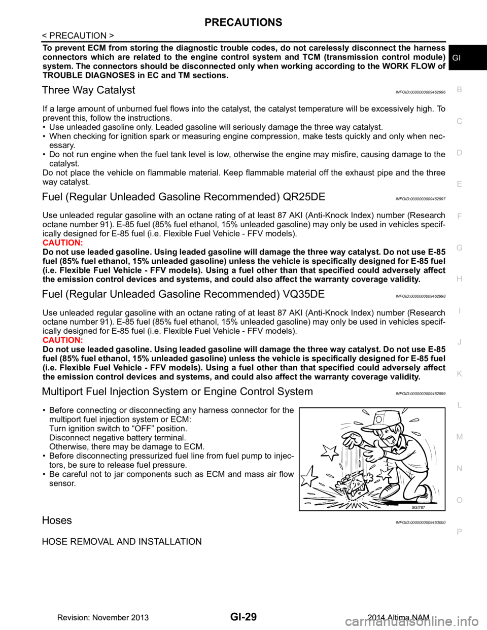
• Before connecting or disconnecti ng any harness connector for the
multiport fuel injection system or ECM:
Turn ignition switch to “OFF” position.
Disconnect negative battery terminal.
Otherwise, there may be damage to ECM.
• Before disconnecting pressurized fuel line from fuel pump to injec-
tors, be sure to release fuel pressure.
• Be careful not to jar components such as ECM and mass air flow sensor.
HosesINFOID:0000000009463000
HOSE REMOVAL AND INSTALLATION
SGI787
Revision: November 20132014 Altima NAMRevision: November 20132014 Altima NAM
Page 2560 of 4801

GI-32
< PRECAUTION >
LIFTING POINT
LIFTING POINT
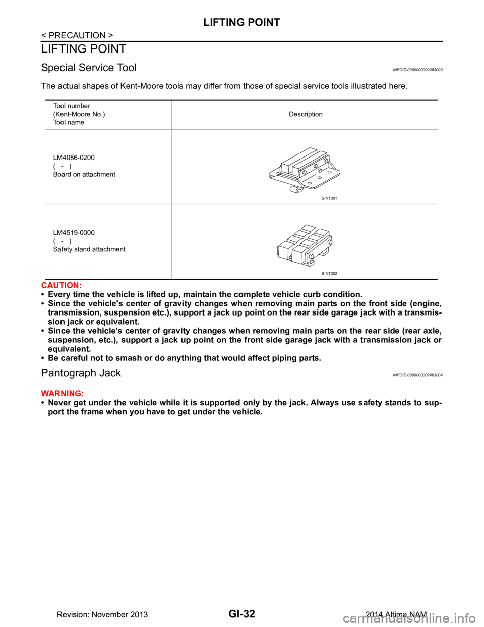
Special Service ToolINFOID:0000000009463003
The actual shapes of Kent-Moore tools may differ from those of special service tools illustrated here.
CAUTION:
• Every time the vehicle is lifted up, main tain the complete vehicle curb condition.
• Since the vehicle's center of gravity changes when removing main parts on the front side (engine,
transmission, suspension etc.), supp ort a jack up point on the rear side garage jack with a transmis-
sion jack or equivalent.
• Since the vehicle's center of gravity changes when removing main parts on the rear side (rear axle,
suspension, etc.), support a jack up point on the front side garage jack with a transmission jack or
equivalent.
• Be careful not to smash or do anythi ng that would affect piping parts.
Pantograph JackINFOID:0000000009463004
WARNING:
• Never get under the vehicle while it is supported only by the jack. Always use safety stands to sup-
port the frame when you have to get under the vehicle.
Tool number
(Kent-Moore No.)
Tool name Description
LM4086-0200
( - )
Board on attachment
LM4519-0000
( - )
Safety stand attachment
S-NT001
S-NT002
Revision: November 20132014 Altima NAMRevision: November 20132014 Altima NAM
Page 2567 of 4801

SERVICE INFORMATION FOR ELECTRICAL INCIDENTGI-39
< BASIC INSPECTION >
C
D E
F
G H
I
J
K L
M B
GI
N
O PBASIC INSPECTION
SERVICE INFORMATION FO R ELECTRICAL INCIDENT
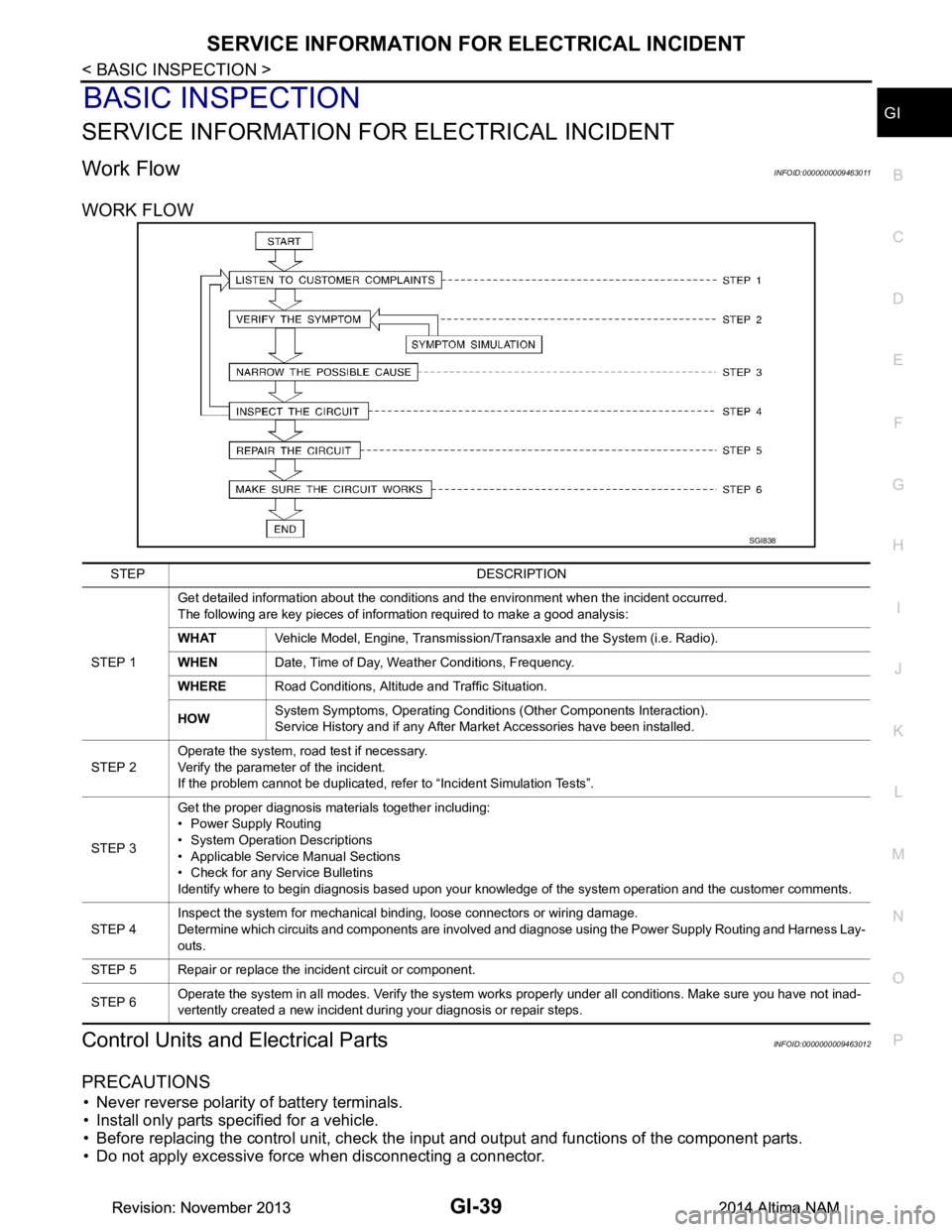
Work FlowINFOID:0000000009463011
WORK FLOW
Control Units and Electrical PartsINFOID:0000000009463012
PRECAUTIONS
• Never reverse polarity of battery terminals.
• Install only parts specified for a vehicle.
• Before replacing the control unit, check the i nput and output and functions of the component parts.
• Do not apply excessive force when disconnecting a connector.
SGI838
STEP DESCRIPTION
STEP 1 Get detailed information about the conditions and the environment when the incident occurred.
The following are key pieces of information required to make a good analysis:
WHAT Vehicle Model, Engine, Transmission/Transaxle and the System (i.e. Radio).
WHEN Date, Time of Day, Weather Conditions, Frequency.
WHERE Road Conditions, Altitude and Traffic Situation.
HOW System Symptoms, Operating Conditions (Other Components Interaction).
Service History and if any After Market Accessories have been installed.
STEP 2 Operate the system, road test if necessary.
Verify the parameter of the incident.
If the problem cannot be duplicated, refer to “Incident Simulation Tests”.
STEP 3 Get the proper diagnosis materials together including:
• Power Supply Routing
• System Operation Descriptions
• Applicable Service Manual Sections
• Check for any Service Bulletins
Identify where to begin diagnosis based upon your knowledge of the system operation and the customer comments.
STEP 4 Inspect the system for mechanical binding, loose connectors or wiring damage.
Determine which circuits and components are involved and diagnose using the Power Supply Routing and Harness Lay-
outs.
STEP 5 Repair or replace the incident circuit or component.
STEP 6 Operate the system in all modes. Verify the system works properly under all conditions. Make sure you have not inad-
vertently created a new incident during your diagnosis or repair steps.
Revision: November 20132014 Altima NAMRevision: November 20132014 Altima NAM