2014 NISSAN TEANA transmission
[x] Cancel search: transmissionPage 2204 of 4801
![NISSAN TEANA 2014 Service Manual
EM-206
< REMOVAL AND INSTALLATION >[VQ35DE]
OIL SEAL
d. Apply sealant to rear oil seal retainer as shown.
Use Genuine Silicone RTV Seal ant, or equivalent. Refer to
GI-21, "Recommended Chemi cal Prod NISSAN TEANA 2014 Service Manual
EM-206
< REMOVAL AND INSTALLATION >[VQ35DE]
OIL SEAL
d. Apply sealant to rear oil seal retainer as shown.
Use Genuine Silicone RTV Seal ant, or equivalent. Refer to
GI-21, "Recommended Chemi cal Prod](/manual-img/5/57390/w960_57390-2203.png)
EM-206
< REMOVAL AND INSTALLATION >[VQ35DE]
OIL SEAL
d. Apply sealant to rear oil seal retainer as shown.
Use Genuine Silicone RTV Seal ant, or equivalent. Refer to
GI-21, "Recommended Chemi cal Products and Sealants"
.
• Assembly should be completed within 5 minutes after coating.
e. Lubricate the sealing surface of the new rear main seal with new engine oil.
f. Slide the new rear main seal (1) over the Tool (A) and onto the crankshaft.
g. Loosen the wing nut and push the threaded rod into the handle to remove the Tool (A).
h. Tighten the rear oil seal retainer bolts to specification.
3. Installation of the remaining components is in the reverse order of removal. CAUTION:
• When replacing an engine or transmission you must make sure the dowels are installed cor-
rectly during re-assembly.
• Improper alignment caused by missing dowels may cause vibration, oil leaks or breakage of
drivetrain components.
AWBIA0028ZZ
ALBIA0653ZZ
Revision: November 20132014 Altima NAM
Page 2219 of 4801
![NISSAN TEANA 2014 Service Manual
ENGINE ASSEMBLYEM-221
< UNIT REMOVAL AND INSTALLATION > [VQ35DE]
C
D E
F
G H
I
J
K L
M A
EM
NP
O
• Do not damage the edge of the crankshaft
position sensor (POS) or the ring gear teeth.
REMOVAL
NISSAN TEANA 2014 Service Manual
ENGINE ASSEMBLYEM-221
< UNIT REMOVAL AND INSTALLATION > [VQ35DE]
C
D E
F
G H
I
J
K L
M A
EM
NP
O
• Do not damage the edge of the crankshaft
position sensor (POS) or the ring gear teeth.
REMOVAL](/manual-img/5/57390/w960_57390-2218.png)
ENGINE ASSEMBLYEM-221
< UNIT REMOVAL AND INSTALLATION > [VQ35DE]
C
D E
F
G H
I
J
K L
M A
EM
NP
O
• Do not damage the edge of the crankshaft
position sensor (POS) or the ring gear teeth.
REMOVAL
NOTE:
When removing components such as hoses, tubes/lines, etc. , cap or plug openings to prevent fluid from spill-
ing.
1. Remove hood assembly. Refer to DLK-170, "HOOD ASSEMBLY : Removal and Installation"
.
2. Release fuel pressure. Refer to FL-5, "Inspection"
.
3. Drain engine coolant. Refer to CO-36, "Changing Engine Coolant"
.
4. Drain power steering fluid. Refer to ST-30, "Draining and Refilling"
.
5. Remove front wheels and tires (RH/LH). Refer to WT-55, "Adjustment"
.
6. Remove fender protector side covers (RH/LH). Refer to EXT-26, "FENDER PROTECTOR : Removal and
Installation".
7. Remove the engine under cover. Refer to EXT-17, "Removal and Installation"
.
8. Remove the engine room cover. Refer to EM-143, "Removal and Installation"
.
9. Remove air duct hose and resonator assembly and air cleaner case assembly with mass air flow sensor.
Refer to EM-144, "Removal and Installation"
.
10. Remove battery and battery tray. Refer to PG-74, "Removal and Installation (Battery Tray)"
.
11. Remove transmission control module. Refer to TM-183, "Removal and Installation"
.
12. Remove cowl top. Refer to EXT-24, "Removal and Installation"
.
13. Remove strut brace using power tools. Refer to FSU-19, "Exploded View"
.
14. Remove IPDM E/R. Refer to PCS-32, "Removal and Installation"
.
15. Remove the following parts: • EVAP vacuum hose
• Brake booster vacuum hose
• Heater hoses (engine side)
16. Disconnect transaxle shift control cables. Refer to TM-380, "Removal and Installation"
.
17. Remove upper and lower radiator hoses.
18. Disconnect CVT fluid cooler hoses.
19. Remove power steering reservoir, suction hose and high pressure hose.
20. Disconnect fuel hose quick connection at vehicle piping side. Refer to EM-163, "Removal and Installa-
tion".
21. Remove the front exhaust tube using power tools. Refer to EX-10, "Exploded View"
.
22. Discharge and recover the R134a refrigerant. Refer to HA-23, "Recycle Refrigerant"
.
23. Remove the A/C compressor using power tools. Refer to HA-30, "COMPRESSOR : Removal and Installa-
tion".
24. Install engine slingers into front of LH cylinder head and rear of RH cylinder head.
• (A): RH cylinder head
ALBIA0262GB
Revision: November 20132014 Altima NAM
Page 2220 of 4801
![NISSAN TEANA 2014 Service Manual
EM-222
< UNIT REMOVAL AND INSTALLATION >[VQ35DE]
ENGINE ASSEMBLY
• (B): LH cylinder head
25. Remove rear cover plate.
26. Remove the torque converter nuts.
27. Remove nuts of stabilizer connectin NISSAN TEANA 2014 Service Manual
EM-222
< UNIT REMOVAL AND INSTALLATION >[VQ35DE]
ENGINE ASSEMBLY
• (B): LH cylinder head
25. Remove rear cover plate.
26. Remove the torque converter nuts.
27. Remove nuts of stabilizer connectin](/manual-img/5/57390/w960_57390-2219.png)
EM-222
< UNIT REMOVAL AND INSTALLATION >[VQ35DE]
ENGINE ASSEMBLY
• (B): LH cylinder head
25. Remove rear cover plate.
26. Remove the torque converter nuts.
27. Remove nuts of stabilizer connecting rods from struts. Refer to FSU-19, "Exploded View"
.
28. Remove front wheel speed sensors and position aside. Refer to BRC-124, "Removal and Installation -
Front Wheel Sensor".
29. Remove front brake rotors. Refer to BR-36, "BRAKE CALIPER ASSEMBLY : Removal and Installation"
.
30. Remove piston rod nut. Refer to FSU-19, "Exploded View"
.
31. Remove front drive shaft (LH/RH). Refer to FAX-10, "Removal and Installation (LH)"
and FAX-12,
"Removal and Installation (RH)".
32. Remove RH drive shaft center bearing bracket.
33. Remove lower steering column pinch bolt. Refer to ST-33, "Exploded View"
.
34. Remove three way catalyst (manifold) (bank 1) heat shield.
35. Disconnect front and rear engine mounting insulator vacuum hoses.
36. Remove front and rear engine mounting insulator nut.
37. Position a suitable support table under suspension member and engine assembly. TM-206, "Removal and
Installation"
38. Disconnect the engine mounting insulator (LH), upper torque rod, and engine mounting insulator (RH).
39. For additional safety, secure the engine in position with suitable tool.
40. Remove suspension member bolts. Refer to FSU-19, "Exploded View"
.
41. Carefully lower the engine, transaxle assembly and suspension member using Tool, avoiding interference
with the vehicle body.
CAUTION:
• Before and during this procedure, alw ays check if any harnesses are left connected.
• Avoid any damage to, or any oil/grease smearin g or spilling onto the engine mounting insula-
tors.
42. Remove the starter motor. Refer to STR-23, "VQ35DE : Removal and Installation"
.
43. Remove the crankshaft position sensor (POS).
44. Remove engine and transaxle harness.
45. Separate the engine and transaxle and mount the engine on a suitable engine stand.
INSTALLATION
Installation is in the reverse order of removal.
NOTE:
Tighten transmission bolts to specification. Refer to TM-206, "Removal and Installation"
.
INSPECTION AFTER INSTALLATION
• Before starting engine, check oil/fluid levels including engine coolant and engine oil. If less than required
quantity, fill to the specified level. Refer to MA-11, "FOR USA AND CANADA : Fluids and Lubricants"
.
• Use procedure below to check for fuel leakage.
• Turn ignition switch ON (with engine stopped). With fuel pressure applied to fuel piping, check for fuel leak-
age at connection points.
ALBIA0263GB
Tool number : KV101J0010 (J-47242)
Revision: November 20132014 Altima NAM
Page 2221 of 4801
![NISSAN TEANA 2014 Service Manual
ENGINE ASSEMBLYEM-223
< UNIT REMOVAL AND INSTALLATION > [VQ35DE]
C
D E
F
G H
I
J
K L
M A
EM
NP
O
• Start engine. With engine speed increased, check again for fuel leakage at connection points.
� NISSAN TEANA 2014 Service Manual
ENGINE ASSEMBLYEM-223
< UNIT REMOVAL AND INSTALLATION > [VQ35DE]
C
D E
F
G H
I
J
K L
M A
EM
NP
O
• Start engine. With engine speed increased, check again for fuel leakage at connection points.
�](/manual-img/5/57390/w960_57390-2220.png)
ENGINE ASSEMBLYEM-223
< UNIT REMOVAL AND INSTALLATION > [VQ35DE]
C
D E
F
G H
I
J
K L
M A
EM
NP
O
• Start engine. With engine speed increased, check again for fuel leakage at connection points.
• Run engine to check for unusual noise and vibration. NOTE:
If hydraulic pressure inside timing chain tensioner dr ops after removal and installation, slack in the guide
may generate a pounding noise during and just after engine start. However, this is normal. Noise will stop
after hydraulic pressure rises.
• Warm up engine thoroughly to make sure there is no leak age of fuel, exhaust gas, or any oils/fluids including
engine oil and engine coolant.
• Bleed air from passages in lines and hoses, such as in cooling system.
• After cooling down engine, again check oil/fluid levels including engine oil and engine coolant. Refill to spec- ified level, if necessary.
• Summary of the inspection items:
*Power steering fluid, brake fluid, etc. Item Before starting engine Engine running After engine stopped
Engine coolant Level Leakage Level
Engine oil Level Leakage Level
Transmission/
transaxle fluid CVT Models Leakage Level/Leakage Leakage
Other oils and fluids* Level Leakage Level
Fuel Leakage Leakage Leakage
Exhaust gas — Leakage —
Revision: November 20132014 Altima NAM
Page 2453 of 4801

FAX-1
TRANSMISSION & DRIVELINE
CEF
G H
I
J
K L
M
SECTION FA X
A
B
FA X
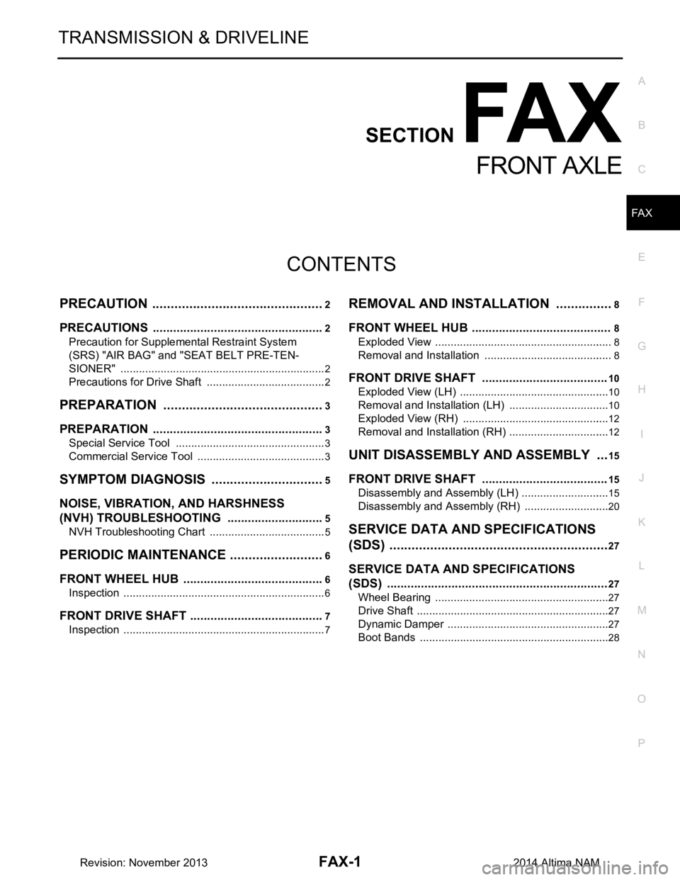
N
O P
CONTENTS
FRONT AXLE
PRECAUTION ................ ...............................2
PRECAUTIONS .............................................. .....2
Precaution for Supplemental Restraint System
(SRS) "AIR BAG" and "SEAT BELT PRE-TEN-
SIONER" ............................................................. ......
2
Precautions for Drive Shaft .......................................2
PREPARATION ............................................3
PREPARATION .............................................. .....3
Special Service Tool ........................................... ......3
Commercial Service Tool ..........................................3
SYMPTOM DIAGNOSIS ...............................5
NOISE, VIBRATION, AND HARSHNESS
(NVH) TROUBLESHOOTING ........................ .....
5
NVH Troubleshooting Chart ................................ ......5
PERIODIC MAINTENANCE ..........................6
FRONT WHEEL HUB ..................................... .....6
Inspection ............................................................ ......6
FRONT DRIVE SHAFT ........................................7
Inspection ............................................................ ......7
REMOVAL AND INSTALLATION ................8
FRONT WHEEL HUB .........................................8
Exploded View ..................................................... .....8
Removal and Installation ..........................................8
FRONT DRIVE SHAFT .....................................10
Exploded View (LH) .................................................10
Removal and Installation (LH) .................................10
Exploded View (RH) ............................................ ....12
Removal and Installation (RH) .................................12
UNIT DISASSEMBLY AND ASSEMBLY ....15
FRONT DRIVE SHAFT .....................................15
Disassembly and Assembly (LH) ......................... ....15
Disassembly and Assembly (RH) ............................20
SERVICE DATA AND SPECIFICATIONS
(SDS) ............... .............................................
27
SERVICE DATA AND SPECIFICATIONS
(SDS) .................................................................
27
Wheel Bearing ..................................................... ....27
Drive Shaft ...............................................................27
Dynamic Damper .....................................................27
Boot Bands ..............................................................28
Revision: November 20132014 Altima NAM
Page 2522 of 4801

FRONT SUSPENSION ASSEMBLYFSU-21
< UNIT REMOVAL AND INSTALLATION >
C
D
F
G H
I
J
K L
M A
B
FSU
N
O P
14. Set Tool under suspension member, and remove suspension member bolts. Slowly lower Tool to remove suspension member from vehicle
15. If replacing suspension member, remove the following components from the suspension member. • transverse links.
• stabilizer bar.
• front suspension member stays.
Installation
Installation is in the reverse order of removal.
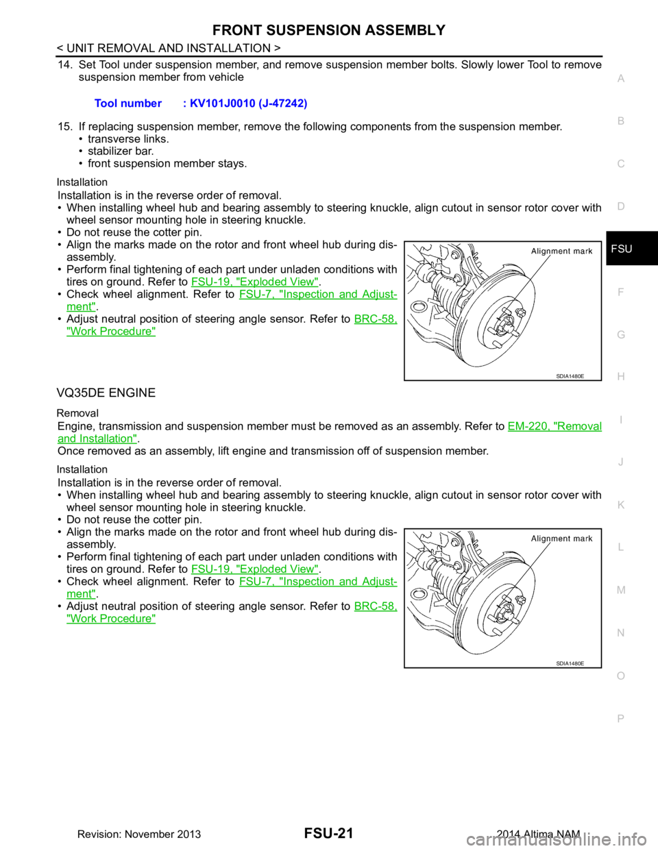
• When installing wheel hub and bearing assembly to steering knuckle, align cutout in sensor rotor cover with wheel sensor mounting hole in steering knuckle.
• Do not reuse the cotter pin.
• Align the marks made on the rotor and front wheel hub during dis- assembly.
• Perform final tightening of each part under unladen conditions with tires on ground. Refer to FSU-19, "Exploded View"
.
• Check wheel alignment. Refer to FSU-7, "Inspection and Adjust-
ment".
• Adjust neutral position of steering angle sensor. Refer to BRC-58,
"Work Procedure"
VQ35DE ENGINE
Removal
Engine, transmission and suspension member must be removed as an assembly. Refer to EM-220, "Removal
and Installation".
Once removed as an assembly, lift engine and transmission off of suspension member.
Installation
Installation is in the reverse order of removal.
• When installing wheel hub and bearing assembly to steering knuckle, align cutout in sensor rotor cover with
wheel sensor mounting hole in steering knuckle.
• Do not reuse the cotter pin.
• Align the marks made on the rotor and front wheel hub during dis-
assembly.
• Perform final tightening of each part under unladen conditions with tires on ground. Refer to FSU-19, "Exploded View"
.
• Check wheel alignment. Refer to FSU-7, "Inspection and Adjust-
ment".
• Adjust neutral position of steering angle sensor. Refer to BRC-58,
"Work Procedure"
Tool number : KV101J0010 (J-47242)
SDIA1480E
SDIA1480E
Revision: November 20132014 Altima NAM
Page 2531 of 4801

HOW TO USE THIS MANUALGI-3
< HOW TO USE THIS MANUAL >
C
D E
F
G H
I
J
K L
M B
GI
N
O PHOW TO USE THIS MANUAL
HOW TO USE THIS MANUAL
DescriptionINFOID:0000000009462967
This volume explains “Removal, Disassembly, Inst allation, Inspection and Adjustment” and “Trouble Diag-
noses”.
Te r m sINFOID:0000000009462968
• The captions WARNING and CAUTION warn you of steps that must be followed to prevent personal injury
and/or damage to some part of the vehicle.
WARNING indicates the possibility of personal injury if instructions are not followed.
CAUTION indicates the possibility of component damage if instructions are not followed.
BOLD TYPED STATEMENTS except WARNING and CAUTION give you helpful information.
Standard value: Tolerance at inspection and adjustment.
Limit value: The maximum or minimum limit val ue that should not be exceeded at inspection and adjust-
ment.
UnitsINFOID:0000000009462969
• The UNITS given in this manual are primarily expressed as the SI UNIT (International System of Unit), and
alternatively expressed in the metric system and in the yard/pound system.
Also with regard to tightening torque of bolts and nuts, there are descriptions both about range and about the
standard tightening torque.
“Example”
Range
Standard
ContentsINFOID:0000000009462970
• A QUICK REFERENCE INDEX , a black tab (e.g. ) is provided on the first page. You can quickly find the
first page of each section by matching it to the section's black tab.
• THE CONTENTS are listed on the first page of each section.
• THE TITLE is indicated on the upper portion of each page and shows the part or system.
• THE PAGE NUMBER of each section consists of two or three letters which designate the particular section
and a number (e.g. “BR-5”).
• THE SMALL ILLUSTRATIONS show the important steps such as ins pection, use of special tools, knacks of
work and hidden or tricky steps which are not s hown in the previous large illustrations.
Assembly, inspection and adjustment procedures for the complicated units such as the automatic transaxle
or transmission, etc. are presented in a step-by-step format where necessary.
Outer Socket Lock Nut : 59 - 78 N·m (6.0 - 8.0 kg-m, 43 - 58 ft-lb)
Drive Shaft Installation Bolt : 44.3 N·m (4.5 kg-m, 33 ft-lb)
Revision: November 20132014 Altima NAMRevision: November 20132014 Altima NAM
Page 2539 of 4801

HOW TO READ WIRING DIAGRAMSGI-11
< HOW TO USE THIS MANUAL >
C
D E
F
G H
I
J
K L
M B
GI
N
O P
DescriptionINFOID:0000000009462978
SWITCH POSITIONS
Switches are shown in wiring diagrams as if the vehicle is in the “normal” condition.
A vehicle is in the “normal” condition when:
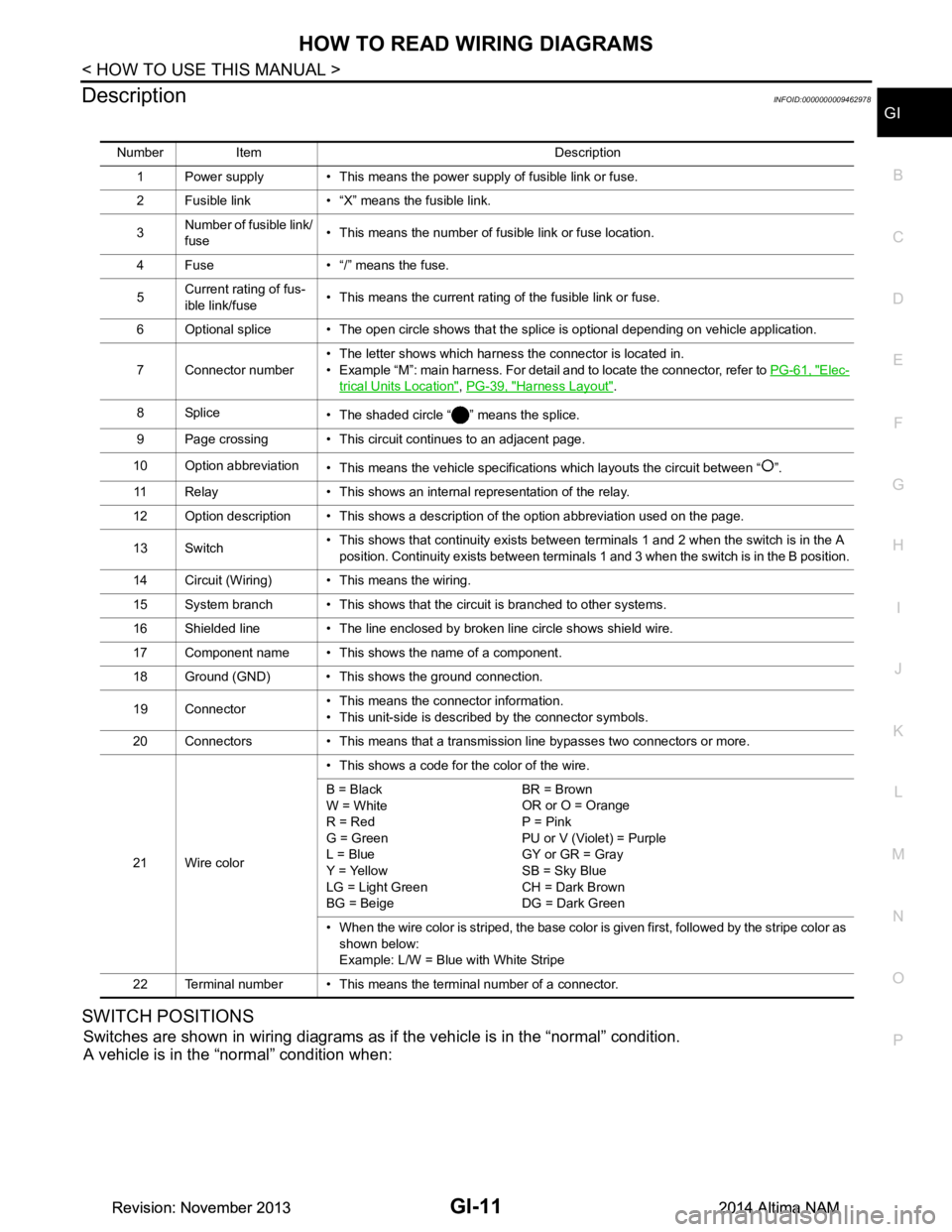
Number Item Description
1 Power supply • This means the power supply of fusible link or fuse.
2 Fusible link • “X” means the fusible link.
3 Number of fusible link/
fuse • This means the number of fusible link or fuse location.
4 Fuse • “/” means the fuse.
5 Current rating of fus-
ible link/fuse • This means the current rating of the fusible link or fuse.
6 Optional splice • The open circle shows that the splice is optional depending on vehicle application.
7 Connector number • The letter shows which harness the connector is located in.
• Example “M”: main harness. For detail and to locate the connector, refer to PG-61, "Elec-
trical Units Location", PG-39, "Harness Layout".
8Splice • The shaded circle “ ” means the splice.
9 Page crossing • This circuit continues to an adjacent page.
10 Option abbreviation • This means the vehicle specifications which layouts the circuit between “ ”.
11 Relay • This shows an internal representation of the relay.
12 Option description • This shows a description of the option abbreviation used on the page.
13 Switch • This shows that continuity exists between terminals 1 and 2 when the switch is in the A
position. Continuity exists between terminals 1 and 3 when the switch is in the B position.
14 Circuit (Wiring) • This means the wiring.
15 System branch • This shows that the circuit is branched to other systems.
16 Shielded line • The line enclosed by broken line circle shows shield wire.
17 Component name • This shows the name of a component.
18 Ground (GND) • This shows the ground connection.
19 Connector • This means the connector information.
• This unit-side is described by the connector symbols.
20 Connectors • This means that a transmission line bypasses two connectors or more.
21 Wire color • This shows a code for the color of the wire.
B = Black
W = White
R = Red
G = Green
L = Blue
Y = Yellow
LG = Light Green
BG = Beige BR = Brown
OR or O = Orange
P = Pink
PU or V (Violet) = Purple
GY or GR = Gray
SB = Sky Blue
CH = Dark Brown
DG = Dark Green
• When the wire color is striped, the base color is given first, followed by the stripe color as shown below:
Example: L/W = Blue with White Stripe
22 Terminal number • This means the terminal number of a connector.
Revision: November 20132014 Altima NAMRevision: November 20132014 Altima NAM