2014 NISSAN TEANA transmission
[x] Cancel search: transmissionPage 3827 of 4801

SEC-2
WIRING DIAGRAM .....................................29
ENGINE START FUNCTION .......................... ...29
Wiring Diagram .................................................... ...29
NISSAN VEHICLE IMMOBILIZER SYSTEM-
NATS ............................................................... ...
40
Wiring Diagram .................................................... ...40
VEHICLE SECURITY SYSTEM .........................50
Wiring Diagram .................................................... ...50
BASIC INSPECTION ...................................63
DIAGNOSIS AND REPAIR WORK FLOW ..... ...63
Work Flow ............................................................ ...63
ADDITIONAL SERVICE WHEN REPLACING
CONTROL UNIT ............................................. ...
66
ECM ........................................................................ ...66
ECM : Description ...................................................66
ECM : Work Procedure ...........................................66
BCM ........................................................................ ...66
BCM : Description ...................................................66
BCM : Work Procedure ...........................................66
DTC/CIRCUIT DIAGNOSIS ...................... ...68
P1610 LOCK MODE ....................................... ...68
Description ........................................................... ...68
DTC Logic ...............................................................68
Diagnosis Procedure ..............................................68
P1611 ID DISCORD, IMMU-ECM ......................69
DTC Logic ............................................................ ...69
Diagnosis Procedure ..............................................69
P1612 CHAIN OF ECM-IMMU ...........................70
DTC Logic ............................................................ ...70
Diagnosis Procedure ..............................................70
P1614 CHAIN OF IMMU-KEY ...........................71
DTC Logic ............................................................ ...71
Diagnosis Procedure ..............................................71
B210B STARTER CONTROL RELAY ..............73
DTC Logic ............................................................ ...73
Diagnosis Procedure ..............................................73
B210C STARTER CONTROL RELAY ..............74
DTC Logic ............................................................ ...74
Diagnosis Procedure ..............................................74
B210D STARTER RELAY .................................76
DTC Logic ............................................................ ...76
Diagnosis Procedure ..............................................76
B210E STARTER RELAY .................................78
DTC Logic ............................................................ ...78
Diagnosis Procedure ..............................................78
B210F TRANSMISSION RANGE SWITCH .......80
Description ........................................................... ...80
DTC Logic ...............................................................80
Diagnosis Procedure ...............................................80
B2110 TRANSMISSION RANGE SWITCH .......82
Description ........................................................... ...82
DTC Logic ...............................................................82
Diagnosis Procedure ...............................................82
B2190 NATS ANTENNA AMP. .........................84
Description ........................................................... ...84
DTC Logic ...............................................................84
Diagnosis Procedure ...............................................84
B2191 DIFFERENCE OF KEY ..........................86
Description ........................................................... ...86
DTC Logic ...............................................................86
Diagnosis Procedure ...............................................86
B2192 ID DISCORD, IMMU-ECM ......................87
DTC Logic ............................................................ ...87
Diagnosis Procedure ...............................................87
B2193 CHAIN OF ECM-IMMU ..........................88
DTC Logic ............................................................ ...88
Diagnosis Procedure ...............................................88
B2195 ANTI-SCANNING ...................................89
DTC Logic ............................................................ ...89
Diagnosis Procedure ...............................................89
B2196 DONGLE UNIT .......................................90
Description ........................................................... ...90
DTC Logic ...............................................................90
Diagnosis Procedure ...............................................90
B2198 NATS ANTENNA AMP. .........................92
DTC Logic ............................................................ ...92
Diagnosis Procedure ...............................................92
B2555 STOP LAMP ...........................................94
DTC Logic ............................................................ ...94
Diagnosis Procedure ...............................................94
Component Inspection ............................................96
B2556 PUSH-BUTTON IGNITION SWITCH .....97
DTC Logic ............................................................ ...97
Diagnosis Procedure ...............................................97
Component Inspection ............................................98
B2557 VEHICLE SPEED ...................................99
DTC Logic ............................................................ ...99
Diagnosis Procedure ...............................................99
B2560 STARTER CONTROL RELAY ..............100
Description ........................................................... .100
DTC Logic .............................................................100
Diagnosis Procedure .............................................100
B2601 SHIFT POSITION ..................................101
DTC Logic ............................................................ .101
Revision: November 20132014 Altima NAMRevision: November 20132014 Altima NAM
Page 3832 of 4801
COMPONENT PARTSSEC-7
< SYSTEM DESCRIPTION >
C
D E
F
G H
I
J
L
M A
B
SEC
N
O P
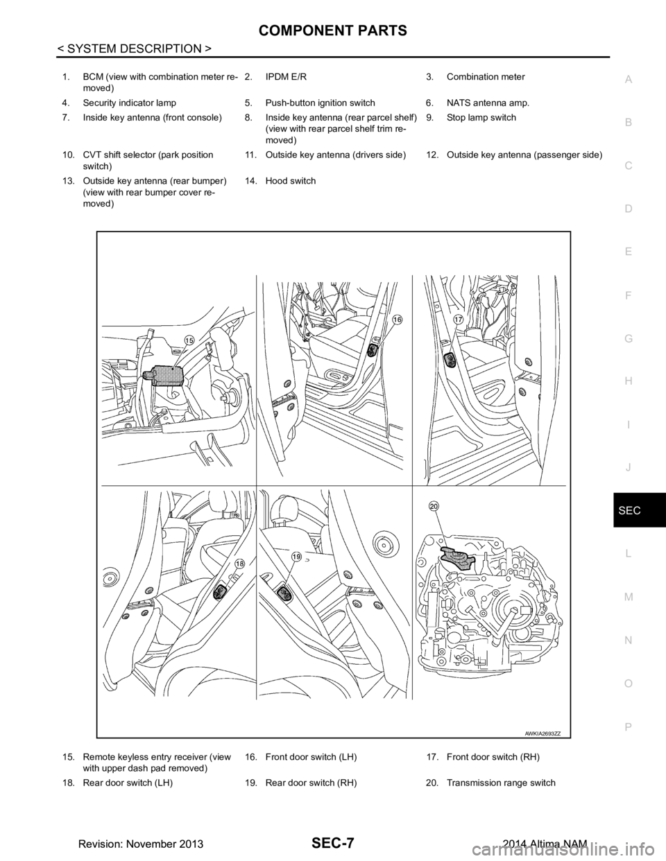
1. BCM (view with combination meter re- moved) 2. IPDM E/R 3. Combination meter
4. Security indicator lamp 5. Push-button ignition switch 6. NATS antenna amp.
7. Inside key antenna (front console) 8. Inside key antenna (rear parcel shelf) (view with rear parcel shelf trim re-
moved) 9. Stop lamp switch
10. CVT shift selector (park position switch) 11. Outside key antenna (drivers side) 12. Outside key antenna (passenger side)
13. Outside key antenna (rear bumper) (view with rear bumper cover re-
moved) 14. Hood switch
15. Remote keyless entry receiver (view with upper dash pad removed) 16. Front door switch (LH) 17. Front door switch (RH)
18. Rear door switch (LH) 19. Rear door switch (RH) 20. Transmission range switch
AWKIA2693ZZ
Revision: November 20132014 Altima NAMRevision: November 20132014 Altima NAM
Page 3833 of 4801
SEC-8
< SYSTEM DESCRIPTION >
COMPONENT PARTS
Component Description
INFOID:0000000009461065
CVT Shift Selector (P ark Position Switch)INFOID:0000000009461066
Park position switch detects that CVT shift selector is in the P (Park) position and then transmits the signal to
BCM and IPDM E/R.
BCM confirms the CVT shift selector position with the following 5 signals:
• P (Park) position signal from CVT shift selector (park position switch)
• P/N position signal from TCM
• P (Park) position signal from IPDM E/R (CAN)
• P/N position signal from IPDM E/R (CAN)
• P/N position signal from TCM (CAN)
IPDM E/R confirms the CVT shift sele ctor position with the following 3 signals:
• P (Park) position signal from CVT shift selector (park position switch)
• P/N position signal from TCM
• P/N position signal from BCM (CAN)
BCMINFOID:0000000009461067
BCM controls INTELLIGENT KE Y SYSTEM (ENGINE START FUNCTIO N), NISSAN VEHICLE IMMOBI-
LIZER SYSTEM-NATS [NVIS (NATS) ], and VEHICLE SECURITY SYSTEM.
BCM performs the ID verification between BCM and Intelligent Key when the Intelligent Key is carried into the
detection area of inside key antenna and push-button ignition swit ch is pressed. If the ID verification result is
OK, push-button ignition switch operation is available.
Then, when the power supply position is turned ON, BCM performs ID verification between BCM and ECM. If
the ID verification result is OK, ECM can start engine.
ECMINFOID:0000000009461068
ECM controls the engine.
When power supply position is turned ON, BCM starts communication with ECM and performs the ID verifica-
tion between BCM and ECM.
Component Reference
CVT shift selector (park position switch) SEC-8
BCMSEC-8
ECMSEC-8
IPDM E/RSEC-9
NATS antenna amp.SEC-9
TCMSEC-9
Combination meterSEC-9
Door switchSEC-9
Hood switchSEC-9
Outside key antennaSEC-9
Inside key antennaSEC-9
Intelligent KeySEC-9
Push-button ignition switchSEC-10
Remote keyless entry receiver SEC-9
Security indicator lampSEC-10
Starter control relaySEC-10
Starter relaySEC-10
Stop lamp switchSEC-10
Transmission range switchSEC-10
Vehicle information displaySEC-10
Revision: November 20132014 Altima NAMRevision: November 20132014 Altima NAM
Page 3835 of 4801

SEC-10
< SYSTEM DESCRIPTION >
COMPONENT PARTS
Push-button Ignition Switch
INFOID:0000000009461079
Push-button ignition switch detects that push-button is pressed and then transmits the signal to BCM. BCM
changes the power supply position with the operation of push-button ignition switch. BCM maintains the power
supply position status while push-button is not operated.
Security Indicator LampINFOID:0000000009461080
Security indicator lamp is located on combination meter.
Security indicator lamp blinks when power supply positi on is any position other than ON to warn that NISSAN
VEHICLE IMMOBILIZER SYSTEM-NATS [NVIS (NATS)] is on board.
Starter Control RelayINFOID:0000000009461081
Engine starting system functions by controlling both starter relay and starter control relay.
Both relays are integrated in IPDM E/R. Starter rela y is controlled by BCM and starter control relay is con-
trolled by IPDM E/R on request from BCM.
IPDM E/R transmits starter relay and starter control relay status signal to BCM via CAN communication.
Starter RelayINFOID:0000000009461082
Engine starting system functions by controlling both starter relay and starter control relay.
Both relays are integrated in IPDM E/R. Starter relay is controlled by BCM, and starter control relay is con-
trolled by IPDM E/R on request from BCM.
IPDM E/R transmits starter relay and starter control relay status signal to BCM via CAN communication.
Stop Lamp SwitchINFOID:0000000009461083
Stop lamp switch detects that brake pedal is depressed, and then transmits the signal to BCM.
Transmission Range SwitchINFOID:0000000009461084
Transmission range switch is integrated in CVT asse mbly, and detects the CVT shift selector position.
TCM receives the transmission range switch signal and then transmits the P/N position signal to BCM and
IPDM E/R.
BCM confirms the CVT shift selector position with the following 5 signals:
• P (Park) position signal from CVT shift selector (park position switch)
• P/N position signal from TCM
• P (Park) position signal from IPDM E/R (CAN)
• P/N position signal from IPDM E/R (CAN)
• P/N position signal from TCM (CAN)
IPDM E/R confirms the CVT shift sele ctor position with the following 3 signals:
• P (Park) position signal from CVT shift selector (park position switch)
• P/N position signal from TCM
• P/N position signal from BCM (CAN)
Vehicle Information DisplayINFOID:0000000009461085
Vehicle information display is integrated in combination meter.
Various information and warnings regarding t he Intelligent Key System are displayed.
Revision: November 20132014 Altima NAMRevision: November 20132014 Altima NAM
Page 3905 of 4801

SEC-80
< DTC/CIRCUIT DIAGNOSIS >
B210F TRANSMISSION RANGE SWITCH
B210F TRANSMISSION RANGE SWITCH
DescriptionINFOID:0000000009461127
IPDM E/R confirms the shift position with the following signals.
• Transmission range switch
• Shift position signal from BCM (CAN)
DTC LogicINFOID:0000000009461128
DTC DETECTION LOGIC
NOTE:
• If DTC B210F is displayed with DTC U1000, first perform the trouble diagnosis for DTC U1000. Refer to BCS-68, "DTC Logic"
.
• If DTC B210F is displayed with DTC U1010, first perform the trouble diagnosis for DTC U1010. Refer to
BCS-69, "DTC Logic"
.
DTC CONFIRMATION PROCEDURE
1.PERFORM DTC CONFIRMATION PROCEDURE
1. Turn ignition switch ON under the following conditions and wait for at least 1 second.
- CVT selector lever is in the P (Park) or N (Neutral) position
- Do not depress the brake pedal
2. Check Self-diagnostic result with CONSULT.
Is DTC detected?
YES >> Refer to SEC-80, "Diagnosis Procedure".
NO >> Inspection End.
Diagnosis ProcedureINFOID:0000000009461129
Regarding Wiring Diagram information, refer to SEC-29, "Wiring Diagram" or SEC-40, "Wiring Diagram".
1.CHECK DTC WITH BCM
Refer to BCS-52, "DTC Index"
.
Is the inspection result normal?
YES >> GO TO 2.
NO >> Repair or replace malfunctioning parts.
2.CHECK TRANSMISSION RANGE SWITCH INPUT SIGNAL
1. Turn ignition switch OFF.
2. Disconnect IPDM E/R harness connector.
3. Turn ignition switch ON.
4. Check voltage between IPDM E/R harness connector E63 terminal 37 and ground under following condi-
tion.
DTC No. Trouble diagnosis name DTC detecting condition Possible cause
B210F TRANSMISSION
RANGE SWITCH IPDM E/R detects a mismatch between the signals
below for 1 second or more.
• Transmission range switch input signal
• Shift position signal from BCM (CAN) • Harness or connectors
Transmission range switch circuit is
open or shorted
• Transmission range switch
Revision: November 20132014 Altima NAMRevision: November 20132014 Altima NAM
Page 3906 of 4801
B210F TRANSMISSION RANGE SWITCHSEC-81
< DTC/CIRCUIT DIAGNOSIS >
C
D E
F
G H
I
J
L
M A
B
SEC
N
O P
Is the inspection result normal?
YES >> Replace IPDM E/R. Refer to PCS-32, "Removal and Installation".
NO >> GO TO 3.
3.CHECK TRANSMISSION RANGE SWITCH CIRCUIT
1. Turn ignition switch OFF.
2. Disconnect the transmission range switch harness connector.
3. Check continuity between IPDM E/R harness connec tor F84 terminal 66 and transmission range switch
harness connector F85 terminal 2.
4. Check continuity between transmission range s witch harness connector F85 terminal 2 and ground.
Is the inspection result normal?
YES >> GO TO 4.
NO >> Repair harness or connector.
4.CHECK INTERMITTENT INCIDENT
Refer to GI-43, "Intermittent Incident"
.
>> Inspection End.
IPDM E/R Ground Condition Voltage (V)
Connector Terminal
E63 37 Ground CVT selector
lever P (Park) or N
(Neutral) Battery voltage
Other than above 0
TRANSMISSION RANGE
SWITCH IPDM E/R
Continuity
Connector Terminal Connector Terminal
F85 2 F84 66 Yes
TRANSMISSION RANGE SWITCH Ground Continuity
Connector Terminal
F85 2 Ground No
Revision: November 20132014 Altima NAMRevision: November 20132014 Altima NAM
Page 3907 of 4801
SEC-82
< DTC/CIRCUIT DIAGNOSIS >
B2110 TRANSMISSION RANGE SWITCH
B2110 TRANSMISSION RANGE SWITCH
DescriptionINFOID:0000000009461130
IPDM E/R confirms the shift position with the following signals.
• Transmission range switch
• Shift position signal from BCM (CAN)
DTC LogicINFOID:0000000009461131
DTC DETECTION LOGIC
NOTE:
• If DTC B2110 is displayed with DTC U1000, first perform the trouble diagnosis for DTC U1000. Refer to BCS-68, "DTC Logic"
.
• If DTC B2110 is displayed with DTC U1010, first perform the trouble diagnosis for DTC U1010. Refer to
BCS-69, "DTC Logic"
.
DTC CONFIRMATION PROCEDURE
1.PERFORM DTC CONFIRMATION PROCEDURE
1. Turn the ignition switch ON under the following conditions and wait for at least 1 second.
- CVT selector lever is in the P (Park) or N (Neutral) position
- Do not depress the brake pedal
2. Check Self-diagnostic result with CONSULT.
Is DTC detected?
YES >> Refer to SEC-82, "Diagnosis Procedure".
NO >> Inspection End.
Diagnosis ProcedureINFOID:0000000009461132
Regarding Wiring Diagram information, refer to SEC-29, "Wiring Diagram" or SEC-40, "Wiring Diagram".
1.CHECK DTC WITH BCM
Refer to BCS-52, "DTC Index"
.
Is the inspection result normal?
YES >> GO TO 2.
NO >> Repair or replace malfunctioning parts.
2.CHECK TRANSMISSION RANGE SWITCH INPUT SIGNAL
1. Turn ignition switch OFF.
2. Disconnect IPDM E/R harness connector.
3. Turn ignition switch ON.
4. Check voltage between IPDM E/R harness connector E63 terminal 37 and ground under following condi-
tion.
DTC No. Trouble diagnosis
name DTC detecting condition Possible cause
B2110 TRANSMISSION
RANGE SWITCH IPDM E/R detects mismatch between the signal
below for 1 second or more.
• Transmission range switch input signal • Harness or connectors
Transmission range switch circuit is
open or shorted
• Transmission range switch
Revision: November 20132014 Altima NAMRevision: November 20132014 Altima NAM
Page 3908 of 4801
B2110 TRANSMISSION RANGE SWITCHSEC-83
< DTC/CIRCUIT DIAGNOSIS >
C
D E
F
G H
I
J
L
M A
B
SEC
N
O P
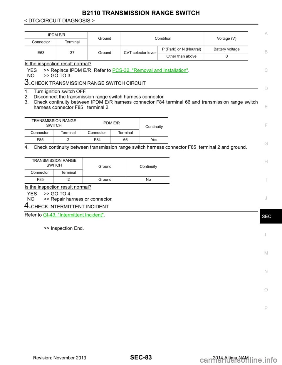
Is the inspection result normal?
YES >> Replace IPDM E/R. Refer to PCS-32, "Removal and Installation".
NO >> GO TO 3.
3.CHECK TRANSMISSION RANGE SWITCH CIRCUIT
1. Turn ignition switch OFF.
2. Disconnect the transmission range switch harness connector.
3. Check continuity between IPDM E/R harness connec tor F84 terminal 66 and transmission range switch
harness connector F85 terminal 2.
4. Check continuity between transmission range s witch harness connector F85 terminal 2 and ground.
Is the inspection result normal?
YES >> GO TO 4.
NO >> Repair harness or connector.
4.CHECK INTERMITTENT INCIDENT
Refer to GI-43, "Intermittent Incident"
.
>> Inspection End.
IPDM E/R Ground Condition Voltage (V)
Connector Terminal
E63 37 Ground CVT selector lever P (Park) or N (Neutral) Battery voltage
Other than above 0
TRANSMISSION RANGE SWITCH IPDM E/R
Continuity
Connector Terminal Connector Terminal
F85 2 F84 66 Yes
TRANSMISSION RANGE SWITCH Ground Continuity
Connector Terminal
F85 2 Ground No
Revision: November 20132014 Altima NAMRevision: November 20132014 Altima NAM