2014 NISSAN TEANA transmission
[x] Cancel search: transmissionPage 4099 of 4801
SRC-106
< DTC/CIRCUIT DIAGNOSIS >
U1000 CAN COMM CIRCUIT
U1000 CAN COMM CIRCUIT
DescriptionINFOID:0000000009460807
CAN (Controller Area Network) is a serial communication system for real time application. It is an on-vehicle
multiplex communication system with high data comm unication speed and excellent error detection ability.
Many electronic control units are equipped into vehicl es, and each control unit shares information and links
with other control units during operation. With CAN co mmunication, control units are connected with two com-
munication lines (CAN-H line, CAN-L line) allowing a hi gh rate of information transmission with less wiring.
Each control unit transmits and receives data but selectively reads required data only. Refer to LAN-32, "CAN
COMMUNICATION SYSTEM : CAN Communication Signal Chart".
DTC LogicINFOID:0000000009460808
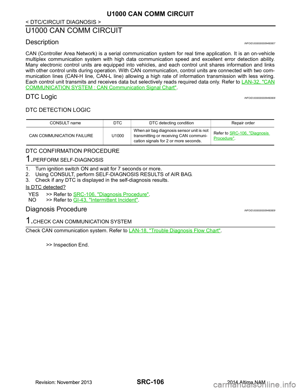
DTC DETECTION LOGIC
DTC CONFIRMATION PROCEDURE
1.PERFORM SELF-DIAGNOSIS
1. Turn ignition switch ON and wait for 7 seconds or more.
2. Using CONSULT, perform SELF-DIAGNOSIS RESULTS of AIR BAG.
3. Check if any DTC is displayed in the self-diagnosis results.
Is DTC detected?
YES >> Refer to SRC-106, "Diagnosis Procedure".
NO >> Refer to GI-43, "Intermittent Incident"
.
Diagnosis ProcedureINFOID:0000000009460809
1.CHECK CAN COMMUNICATION SYSTEM
Check CAN communication system. Refer to LAN-18, "Trouble Diagnosis Flow Chart"
.
>> Inspection End.
CONSULT name DTC DTC detecting condition Repair order
CAN COMMUNICATION FAILURE U1000 When air bag diagnosis sensor unit is not
transmitting or receiving CAN communi-
cation signals for 2 or more seconds. Refer to
SRC-106, "Diagnosis
Procedure".
Revision: November 20132014 Altima NAMRevision: November 20132014 Altima NAM
Page 4181 of 4801
STC-30
< DTC/CIRCUIT DIAGNOSIS >
U1000 CAN COMM CIRCUIT
U1000 CAN COMM CIRCUIT
DescriptionINFOID:0000000009460367
CAN (Controller Area Network) is a serial communication line for real time application. It is an on-vehicle mul-
tiplex communication line with high data communication s peed and excellent error detection ability. Many elec-
tronic control units are equipped onto a vehicle, and each control unit shares information and links with other
control units during operation (not independent). In CA N communication, control units are connected with 2
communication lines (CAN-H line, CAN-L line) allowing a high rate of information transmission with less wiring.
Each control unit communicate data but selectively reads required data only.
DTC LogicINFOID:0000000009460368
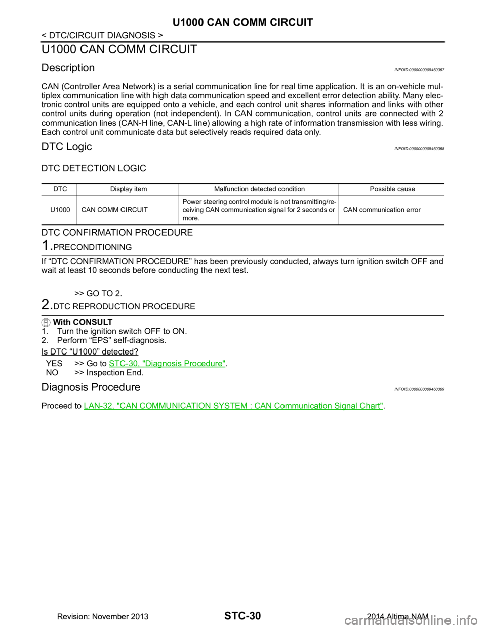
DTC DETECTION LOGIC
DTC CONFIRMATION PROCEDURE
1.PRECONDITIONING
If “DTC CONFIRMATION PROCEDURE” has been previously conducted, always turn ignition switch OFF and
wait at least 10 seconds before conducting the next test.
>> GO TO 2.
2.DTC REPRODUCTION PROCEDURE
With CONSULT
1. Turn the ignition switch OFF to ON.
2. Perform “EPS” self-diagnosis.
Is DTC
“U1000” detected?
YES >> Go to STC-30, "Diagnosis Procedure".
NO >> Inspection End.
Diagnosis ProcedureINFOID:0000000009460369
Proceed to LAN-32, "CAN COMMUNICATION SYSTEM : CAN Communication Signal Chart".
DTC Display item Malfunction detected condition Possible cause
U1000 CAN COMM CIRCUIT Power steering control module is not transmitting/re-
ceiving CAN communication signal for 2 seconds or
more. CAN communication error
Revision: November 20132014 Altima NAMRevision: November 20132014 Altima NAM
Page 4194 of 4801
STR-4
< SYSTEM DESCRIPTION >
COMPONENT PARTS
SYSTEM DESCRIPTION
COMPONENT PARTS
QR25DE
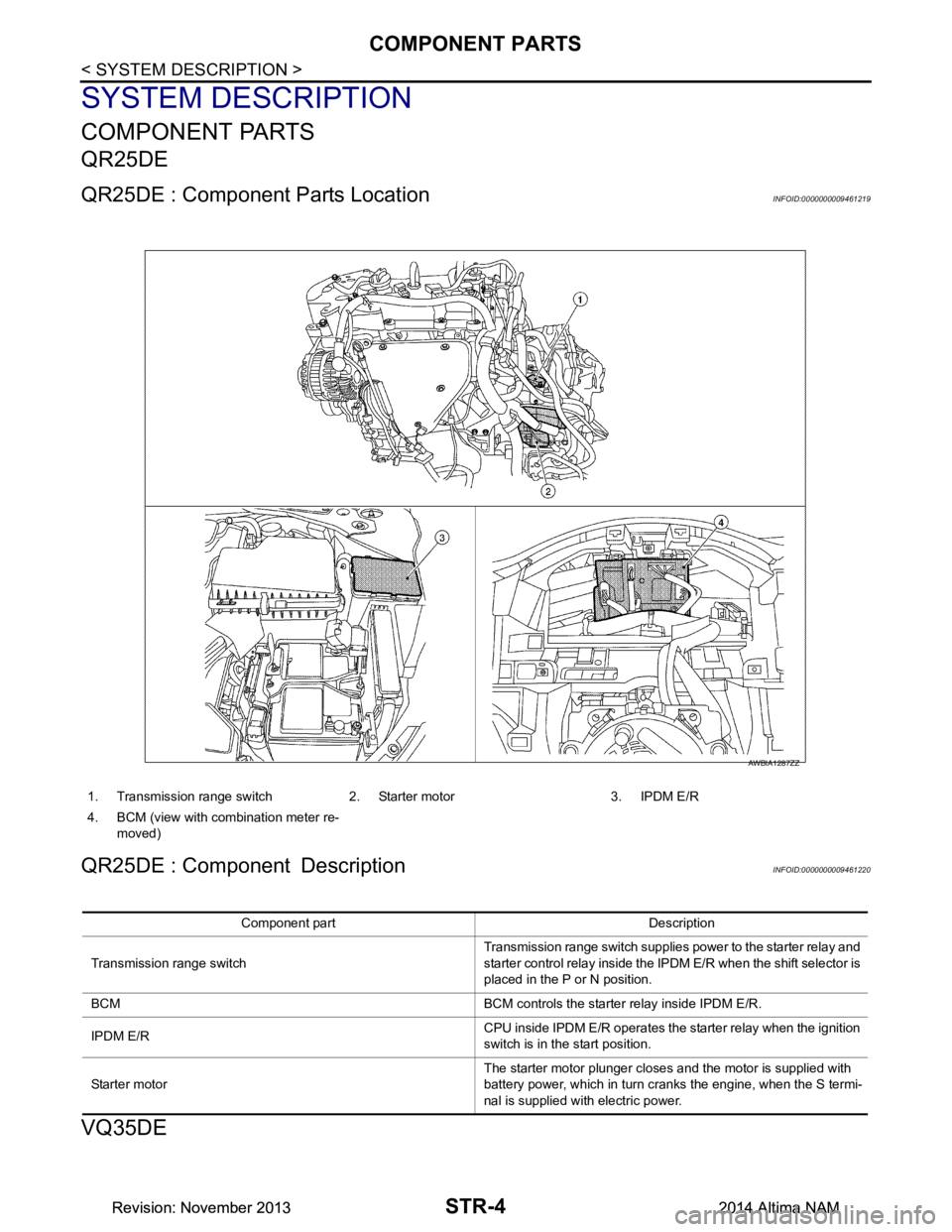
QR25DE : Component Parts LocationINFOID:0000000009461219
QR25DE : Component DescriptionINFOID:0000000009461220
VQ35DE
1. Transmission range switch 2. Starter motor 3. IPDM E/R
4. BCM (view with combination meter re- moved)
AWBIA1287ZZ
Component part Description
Transmission range switch Transmission range switch supplies power to the starter relay and
starter control relay inside the IPDM E/R when the shift selector is
placed in the P or N position.
BCM BCM controls the starter relay inside IPDM E/R.
IPDM E/R CPU inside IPDM E/R operates the starter relay when the ignition
switch is in the start position.
Starter motor The starter motor plunger closes and the motor is supplied with
battery power, which in turn cranks the engine, when the S termi-
nal is supplied with electric power.
Revision: November 20132014 Altima NAMRevision: November 20132014 Altima NAM
Page 4195 of 4801
COMPONENT PARTSSTR-5
< SYSTEM DESCRIPTION >
C
D E
F
G H
I
J
K L
M A
STR
NP
O
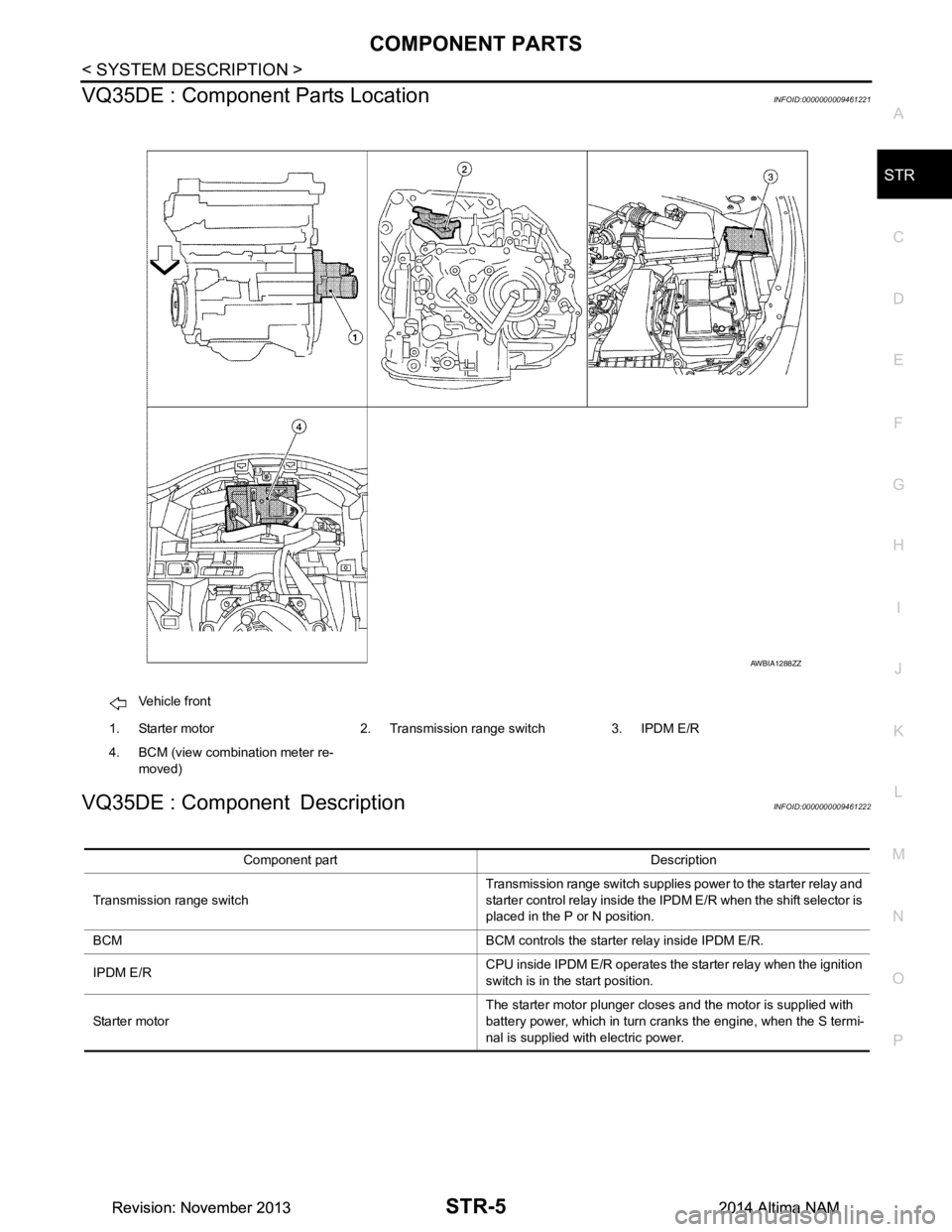
VQ35DE : Component Parts LocationINFOID:0000000009461221
VQ35DE : Component DescriptionINFOID:0000000009461222
Vehicle front
1. Starter motor 2. Transmission range switch 3. IPDM E/R
4. BCM (view combination meter re- moved)
AWBIA1288ZZ
Component part Description
Transmission range switch Transmission range switch supplies power to the starter relay and
starter control relay inside the IPDM E/R when the shift selector is
placed in the P or N position.
BCM BCM controls the starter relay inside IPDM E/R.
IPDM E/R CPU inside IPDM E/R operates the starter relay when the ignition
switch is in the start position.
Starter motor The starter motor plunger closes and the motor is supplied with
battery power, which in turn cranks the engine, when the S termi-
nal is supplied with electric power.
Revision: November 20132014 Altima NAMRevision: November 20132014 Altima NAM
Page 4196 of 4801
STR-6
< SYSTEM DESCRIPTION >
SYSTEM
SYSTEM
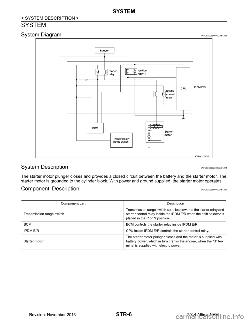
System DiagramINFOID:0000000009461223
System DescriptionINFOID:0000000009461224
The starter motor plunger closes and provides a closed circuit between the battery and the starter motor. The
starter motor is grounded to the cylinder block. With power and ground supplied, the starter motor operates.
Component DescriptionINFOID:0000000009461225
AWBIA1774GB
Component part Description
Transmission range switch Transmission range switch supplies power to the starter relay and
starter control relay inside the IPDM E/R when the shift selector is
placed in the P or N position.
BCM BCM controls the starter relay inside IPDM E/R.
IPDM E/R CPU inside IPDM E/R controls the starter control relay.
Starter motor The starter motor plunger closes and the motor is supplied with
battery power, which in turn cranks the engine, when the “S” ter-
minal is supplied with electric power.
Revision: November 20132014 Altima NAMRevision: November 20132014 Altima NAM
Page 4216 of 4801
TM-1
TRANSMISSION & DRIVELINE
CEF
G H
I
J
K L
M
SECTION TM
A
B
TM
N
O P
CONTENTS
TRANSAXLE & TRANSMISSION
CVT: RE0F10D
PRECAUTION ................ ...............................
9
PRECAUTIONS .............................................. .....9
Precaution for Supplemental Restraint System
(SRS) "AIR BAG" and "SEAT BELT PRE-TEN-
SIONER" ............................................................. ......
9
Precaution for Procedure without Cowl Top Cover ......9
Precaution for TCM and Transaxle Assembly Re-
placement ............................................................ ......
9
General Precautions ...............................................10
On Board Diagnosis (OBD) System of CVT and
Engine ................................................................. ....
11
Removal and Installation Procedure for CVT Unit
Connector ............................................................ ....
11
PREPARATION ...........................................13
PREPARATION .............................................. ....13
Special Service Tools .......................................... ....13
Commercial Service Tools ......................................13
SYSTEM DESCRIPTION .............................14
COMPONENT PARTS ................................... ....14
CVT CONTROL SYSTEM .........................................14
CVT CONTROL SYSTEM : Component Parts Lo-
cation ................................................................... ....
14
CVT CONTROL SYSTEM : TCM ............................16
CVT CONTROL SYSTEM : Transmission Range
Switch .................................................................. ....
16
CVT CONTROL SYSTEM : Primary Speed Sen-
sor ....................................................................... ....
16
CVT CONTROL SYSTEM : Output Speed Sensor ....16
CVT CONTROL SYSTEM : In put Speed Sensor ....17
CVT CONTROL SYSTEM : CVT Fluid Tempera-
ture Sensor .......................................................... ....
17
CVT CONTROL SYSTEM : Primary Pressure
Sensor ................................................................. ....
18
CVT CONTROL SYSTEM : Secondary Pressure
Sensor ................................................................. ....
18
CVT CONTROL SYSTEM : Primary Pressure So-
lenoid Valve ......................................................... ....
19
CVT CONTROL SYSTEM : Secondary Pressure
Solenoid Valve ..................................................... ....
19
CVT CONTROL SYSTEM : Select Solenoid Valve
....
19
CVT CONTROL SYSTEM : Torque Converter
Clutch Solenoid Valve ......................................... ....
19
CVT CONTROL SYSTEM : Line Pressure Sole-
noid Valve ............................................................ ....
20
CVT CONTROL SYSTEM : Overdrive Control
Switch .................................................................. ....
20
CVT CONTROL SYSTEM : O/D OFF Indicator
Lamp .................................................................... ....
20
CVT CONTROL SYSTEM : Shift Position Indica-
tor ........................................................................ ....
20
SHIFT LOCK SYSTEM ..............................................20
SHIFT LOCK SYSTEM : Component Parts Loca-
tion ....................................................................... ....
21
STRUCTURE AND OPERATION .....................22
TRANSAXLE .......................................................... ....22
TRANSAXLE : Cross-Sectional View ......................22
TRANSAXLE : Operation Stat us .............................23
TRANSAXLE : Transaxle Me chanism .....................23
TRANSAXLE : Oil Pressure System .......................26
TRANSAXLE : Component De scription ...................27
FLUID COOLER & FLUID WARMER SYSTEM .... ....27
FLUID COOLER & FLUID WARMER SYSTEM :
System Description .............................................. ....
28
SHIFT LOCK SYSTEM ..............................................28
SHIFT LOCK SYSTEM : Syst em Description ..........28
SYSTEM ...................... ......................................30
CVT CONTROL SYSTEM ..... .....................................30
CVT CONTROL SYSTEM : S ystem Description .....30
Revision: November 20132014 Altima NAMRevision: November 20132014 Altima NAM
Page 4217 of 4801

TM-2
CVT CONTROL SYSTEM : Fail-safe .................. ...31
CVT CONTROL SYSTEM : Protection Control ... ...34
LINE PRESSURE CONTROL ................................ ...35
LINE PRESSURE CONTROL : System Descrip-
tion ....................................................................... ...
35
SHIFT CONTROL ................................................... ...35
SHIFT CONTROL : System Description .................36
SELECT CONTROL ............................................... ...37
SELECT CONTROL : System Description .............38
LOCK-UP CONTROL ............................................. ...38
LOCK-UP CONTROL : System Description ...........38
ON BOARD DIAGNOSTIC (OBD) SYSTEM .....40
Description ........................................................... ...40
Function of OBD .....................................................40
DIAGNOSIS SYSTEM (TCM) ............................41
DIAGNOSIS DESCRIPTION .................................. ...41
DIAGNOSIS DESCRIPTION : 1 Trip Detection Di-
agnosis and 2 Trip Detection Diagnosis .............. ...
41
DIAGNOSIS DESCRIPTION : DTC and DTC of
1st Trip ................................................................. ...
41
DIAGNOSIS DESCRIPTION : Malfunction Indica-
tor Lamp (MIL) ..................................................... ...
41
DIAGNOSIS DESCRIPTION : Counter System .....41
CONSULT Function ................................................43
ECU DIAGNOSIS INFORMATION ..............49
TCM ................................................................. ...49
Reference Value .................................................. ...49
Fail-safe ..................................................................56
Protection Control ...................................................59
DTC Inspection Priority Chart .................................59
DTC Index ..............................................................60
WIRING DIAGRAM .....................................62
CVT CONTROL SYSTEM ............................... ...62
Wiring diagram .................................................... ...62
CVT SHIFT LOCK SYSTEM ........................... ...73
Wiring diagram .................................................... ...73
BASIC INSPECTION ...................................77
DIAGNOSIS AND REPAIR WORK FLOW ..... ...77
Flowchart of Trouble Diagnosis ........................... ...77
Question sheet .......................................................78
ADDITIONAL SERVICE WHEN REPLACING
TCM ................................................................. ...
80
Description ........................................................... ...80
Work Procedure ......................................................80
ADDITIONAL SERVICE WHEN REPLACING
TRANSAXLE ASSEMBLY ............................. ...
81
Description ........................................................... ...81
Work Procedure ................................................... ...81
CVT FLUID ........................................................83
Replacement ........................................................ ...83
Adjustment ..............................................................84
STALL TEST .....................................................86
Work Procedure ................................................... ...86
CVT POSITION ..................................................87
Inspection ............................................................. ...87
Adjustment ..............................................................87
DTC/CIRCUIT DIAGNOSIS ........................88
U0073 COMMUNICATION BUS A OFF ......... ...88
DTC Logic ............................................................ ...88
Diagnosis Procedure ...............................................88
U0100 LOST COMMUNICATION (ECM A) .......89
DTC Logic ............................................................ ...89
Diagnosis Procedure ...............................................89
U0140 LOST COMMUNICATION (BCM) ..........90
DTC Logic ............................................................ ...90
Diagnosis Procedure ...............................................90
U0141 LOST COMMUNICATION (BCM A) ......91
DTC Logic ............................................................ ...91
Diagnosis Procedure ...............................................91
U0155 LOST COMMUNICATION (IPC) ............92
DTC Logic ............................................................ ...92
Diagnosis Procedure ...............................................92
U0300 CAN COMMUNICATION DATA ............93
DTC Logic ............................................................ ...93
Diagnosis Procedure ...............................................93
U1000 CAN COMM CIRCUIT ............................94
Description ........................................................... ...94
DTC Logic ...............................................................94
Diagnosis Procedure ...............................................94
U1117 LOST COMMUNICATION (ABS) ...........95
DTC Logic ............................................................ ...95
Diagnosis Procedure ...............................................95
P062F EEPROM ................................................96
Description ........................................................... ...96
DTC Logic ...............................................................96
Diagnosis Procedure ...............................................96
P0705 TRANSMISSION RANGE SENSOR A ...97
DTC Logic ............................................................ ...97
Diagnosis Procedure ...............................................97
Component Inspection ..........................................101
P0706 TRANSMISSION RANGE SENSOR A ..103
DTC Logic ............................................................ .103
Diagnosis Procedure .............................................103
Component Inspection ..........................................105
Revision: November 20132014 Altima NAMRevision: November 20132014 Altima NAM
Page 4218 of 4801
TM-3
CEF
G H
I
J
K L
M A
B
TM
N
O P
P0711 TRANSMISSION FLUID TEMPERA-
TURE SENSOR A .......................................... ..
106
DTC Logic ........................................................... ..106
Diagnosis Procedure .............................................107
P0712 TRANSMISSION FLUID TEMPERA-
TURE SENSOR A .......................................... ..
110
DTC Logic ........................................................... ..110
Diagnosis Procedure .............................................110
Component Inspection ..........................................110
P0713 TRANSMISSION FLUID TEMPERA-
TURE SENSOR A .......................................... ..
112
DTC Logic ........................................................... ..112
Diagnosis Procedure .............................................112
Component Inspection ..........................................113
P0715 INPUT SPEED SENSOR A ...................114
DTC Logic ........................................................... ..114
Diagnosis Procedure .............................................115
P0717 INPUT SPEED SENSOR A ...................117
DTC Logic ........................................................... ..117
Diagnosis Procedure .............................................118
P0740 TORQUE CONVERTER ........................120
DTC Logic ........................................................... ..120
Diagnosis Procedure .............................................121
P0743 TORQUE CONVERTER ........................122
DTC Logic ........................................................... ..122
Diagnosis Procedure .............................................123
P0744 TORQUE CONVERTER ........................124
DTC Logic ........................................................... ..124
Diagnosis Procedure .............................................125
P0746 PRESSURE CONTROL SOLENOID A ..126
DTC Logic ........................................................... ..126
Diagnosis Procedure .............................................127
P0776 PRESSURE CONTROL SOLENOID B ..128
DTC Logic ........................................................... ..128
Diagnosis Procedure .............................................129
P0778 PRESSURE CONTROL SOLENOID B ..130
DTC Logic ........................................................... ..130
Diagnosis Procedure .............................................130
P0779 PRESSURE CONTROL SOLENOID B ..132
DTC Logic ........................................................... ..132
Diagnosis Procedure .............................................132
P0841 TRANSMISSION FLUID PRESSURE
SEN/SW A ...................................................... ..
134
DTC Logic ........................................................... ..134
Diagnosis Procedure .............................................134
P0847 TRANSMISSION FLUID PRESSURE
SEN/SW B ...................................................... ..
135
DTC Logic ........................................................... ..135
Diagnosis Procedure ........................................... ..135
P0848 TRANSMISSION FLUID PRESSURE
SEN/SW B .......................................................
137
DTC Logic ............................................................ ..137
Diagnosis Procedure .............................................137
P084C TRANSMISSION FLUID PRESSURE
SEN/SW H .......................................................
139
DTC Logic ............................................................ ..139
Diagnosis Procedure .............................................139
P084D TRANSMISSION FLUID PRESSURE
SEN/SW H .......................................................
141
DTC Logic ............................................................ ..141
Diagnosis Procedure .............................................141
P0863 TCM COMMUNICATION .....................143
DTC Logic ..............................................................143
Diagnosis Procedure .............................................143
P0890 TCM ......................................................144
DTC Logic ..............................................................144
Diagnosis Procedure .............................................144
P0962 PRESSURE CONTROL SOLENOID A .145
DTC Logic ............................................................ ..145
Diagnosis Procedure .............................................145
P0963 PRESSURE CONTROL SOLENOID A .147
DTC Logic ............................................................ ..147
Diagnosis Procedure .............................................147
P0965 PRESSURE CONTROL SOLENOID B .149
DTC Logic ............................................................ ..149
Diagnosis Procedure .............................................150
P0966 PRESSURE CONTROL SOLENOID B .151
DTC Logic ............................................................ ..151
Diagnosis Procedure .............................................151
P0967 PRESSURE CONTROL SOLENOID B .153
DTC Logic ............................................................ ..153
Diagnosis Procedure .............................................153
P2765 INPUT SPEED SENSOR B ..................155
DTC Logic ..............................................................155
Diagnosis Procedure .............................................156
P2813 SELECT SOLENOID ...........................158
DTC Logic ..............................................................158
Diagnosis Procedure .............................................159
P2814 SELECT SOLENOID ...........................160
DTC Logic ..............................................................160
Diagnosis Procedure .............................................160
P2815 SELECT SOLENOID ...........................162
DTC Logic ..............................................................162
Diagnosis Procedure .............................................162
Revision: November 20132014 Altima NAMRevision: November 20132014 Altima NAM