2014 NISSAN TEANA check engine
[x] Cancel search: check enginePage 3929 of 4801
SEC-104
< DTC/CIRCUIT DIAGNOSIS >
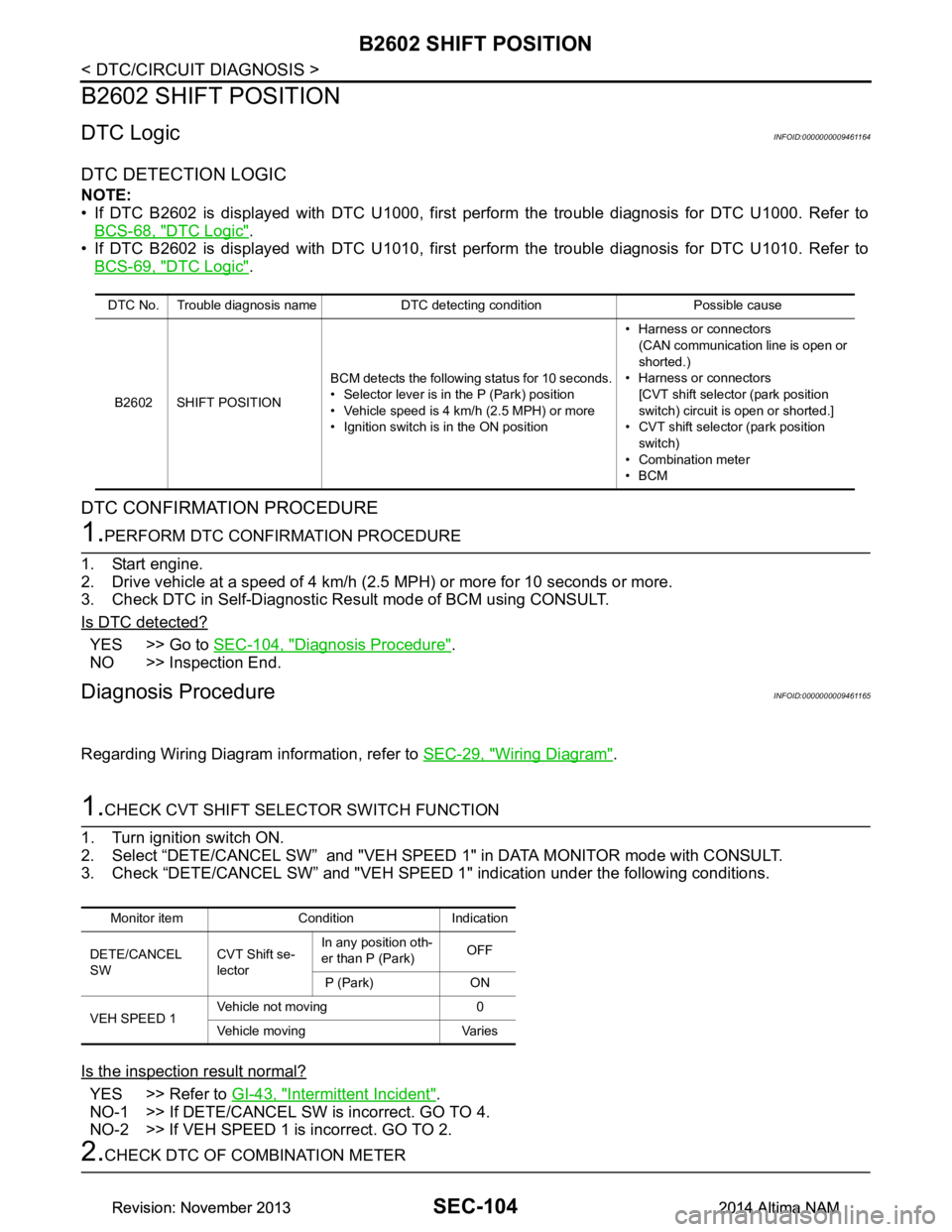
B2602 SHIFT POSITION
B2602 SHIFT POSITION
DTC LogicINFOID:0000000009461164
DTC DETECTION LOGIC
NOTE:
• If DTC B2602 is displayed with DTC U1000, first perform the trouble diagnosis for DTC U1000. Refer to
BCS-68, "DTC Logic"
.
• If DTC B2602 is displayed with DTC U1010, first perform the trouble diagnosis for DTC U1010. Refer to BCS-69, "DTC Logic"
.
DTC CONFIRMATION PROCEDURE
1.PERFORM DTC CONFIRMATION PROCEDURE
1. Start engine.
2. Drive vehicle at a speed of 4 km/h (2.5 MPH) or more for 10 seconds or more.
3. Check DTC in Self-Diagnostic Result mode of BCM using CONSULT.
Is DTC detected?
YES >> Go to SEC-104, "Diagnosis Procedure".
NO >> Inspection End.
Diagnosis ProcedureINFOID:0000000009461165
Regarding Wiring Diagram information, refer to SEC-29, "Wiring Diagram".
1.CHECK CVT SHIFT SELECTOR SWITCH FUNCTION
1. Turn ignition switch ON.
2. Select “DETE/CANCEL SW” and "VEH SPEED 1" in DATA MONITOR mode with CONSULT.
3. Check “DETE/CANCEL SW” and "VEH SPEED 1" indication under the following conditions.
Is the inspection result normal?
YES >> Refer to GI-43, "Intermittent Incident".
NO-1 >> If DETE/CANCEL SW is incorrect. GO TO 4.
NO-2 >> If VEH SPEED 1 is incorrect. GO TO 2.
2.CHECK DTC OF COMBINATION METER
DTC No. Trouble diagnosis name DTC detecting condition Possible cause
B2602 SHIFT POSITION BCM detects the following status for 10 seconds.
• Selector lever is in the P (Park) position
• Vehicle speed is 4 km/h (2.5 MPH) or more
• Ignition switch is in the ON position • Harness or connectors
(CAN communication line is open or
shorted.)
• Harness or connectors [CVT shift selector (park position
switch) circuit is open or shorted.]
• CVT shift selector (park position switch)
• Combination meter
•BCM
Monitor item Condition Indication
DETE/CANCEL
SW CVT Shift se-
lector In any position oth-
er than P (Park) OFF
P (Park) ON
VEH SPEED 1 Vehicle not moving 0
Vehicle moving Varies
Revision: November 20132014 Altima NAMRevision: November 20132014 Altima NAM
Page 3941 of 4801
SEC-116
< DTC/CIRCUIT DIAGNOSIS >
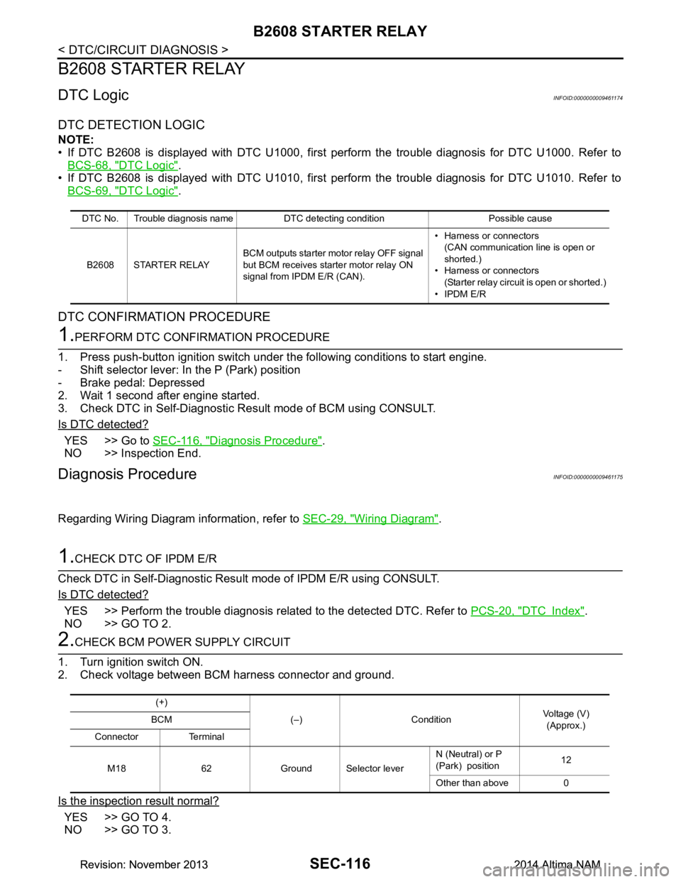
B2608 STARTER RELAY
B2608 STARTER RELAY
DTC LogicINFOID:0000000009461174
DTC DETECTION LOGIC
NOTE:
• If DTC B2608 is displayed with DTC U1000, first perform the trouble diagnosis for DTC U1000. Refer to
BCS-68, "DTC Logic"
.
• If DTC B2608 is displayed with DTC U1010, first perform the trouble diagnosis for DTC U1010. Refer to BCS-69, "DTC Logic"
.
DTC CONFIRMATION PROCEDURE
1.PERFORM DTC CONFIRMATION PROCEDURE
1. Press push-button ignition switch under t he following conditions to start engine.
- Shift selector lever: In the P (Park) position
- Brake pedal: Depressed
2. Wait 1 second after engine started.
3. Check DTC in Self-Diagnostic Result mode of BCM using CONSULT.
Is DTC detected?
YES >> Go to SEC-116, "Diagnosis Procedure".
NO >> Inspection End.
Diagnosis ProcedureINFOID:0000000009461175
Regarding Wiring Diagram information, refer to SEC-29, "Wiring Diagram".
1.CHECK DTC OF IPDM E/R
Check DTC in Self-Diagnostic Result mode of IPDM E/R using CONSULT.
Is DTC detected?
YES >> Perform the trouble diagnosis relat ed to the detected DTC. Refer to PCS-20, "DTC Index".
NO >> GO TO 2.
2.CHECK BCM POWER SUPPLY CIRCUIT
1. Turn ignition switch ON.
2. Check voltage between BCM harness connector and ground.
Is the inspection result normal?
YES >> GO TO 4.
NO >> GO TO 3.
DTC No. Trouble diagnosis name DTC detecting condition Possible cause
B2608 STARTER RELAY BCM outputs starter motor relay OFF signal
but BCM receives star ter motor relay ON
signal from IPDM E/R (CAN). • Harness or connectors
(CAN communication line is open or
shorted.)
• Harness or connectors (Starter relay circuit is open or shorted.)
• IPDM E/R
(+)
(–) Condition Voltage (V)
(Approx.)
BCM
Connector Terminal
M18 62 Ground Selector lever N (Neutral) or P
(Park) position 12
Other than above 0
Revision: November 20132014 Altima NAMRevision: November 20132014 Altima NAM
Page 3954 of 4801
ENGINE DOES NOT START WHEN INTELLIGENT KEY IS INSIDE OF VEHICLE
SEC-129
< SYMPTOM DIAGNOSIS >
C
D E
F
G H
I
J
L
M A
B
SEC
N
O P
SYMPTOM DIAGNOSIS
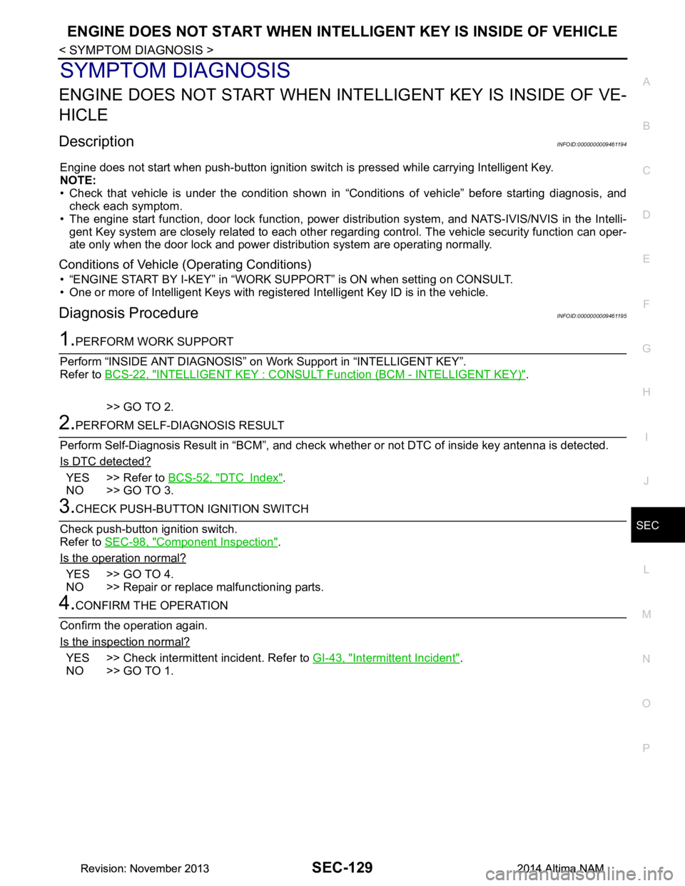
ENGINE DOES NOT START WHEN IN TELLIGENT KEY IS INSIDE OF VE-
HICLE
DescriptionINFOID:0000000009461194
Engine does not start when push-button ignition swit ch is pressed while carrying Intelligent Key.
NOTE:
• Check that vehicle is under the condition shown in “Conditions of vehicle” before starting diagnosis, and
check each symptom.
• The engine start function, door lock function, power dist ribution system, and NATS-IVIS/NVIS in the Intelli-
gent Key system are closely related to each other regar ding control. The vehicle security function can oper-
ate only when the door lock and power distribution system are operating normally.
Conditions of Vehicle (Operating Conditions)
• “ENGINE START BY I-KEY” in “WORK SUPPORT” is ON when setting on CONSULT.
• One or more of Intelligent Keys with registered Intelligent Key ID is in the vehicle.
Diagnosis ProcedureINFOID:0000000009461195
1.PERFORM WORK SUPPORT
Perform “INSIDE ANT DIAGNOSIS” on Wo rk Support in “INTELLIGENT KEY”.
Refer to BCS-22, "INTELLIGENT KEY : CONSUL T Function (BCM - INTELLIGENT KEY)"
.
>> GO TO 2.
2.PERFORM SELF-DIAGNOSIS RESULT
Perform Self-Diagnosis Result in “BCM”, and check whether or not DTC of inside key antenna is detected.
Is DTC detected?
YES >> Refer to BCS-52, "DTC Index".
NO >> GO TO 3.
3.CHECK PUSH-BUTTON IGNITION SWITCH
Check push-button ignition switch.
Refer to SEC-98, "Component Inspection"
.
Is the operation normal?
YES >> GO TO 4.
NO >> Repair or replace malfunctioning parts.
4.CONFIRM THE OPERATION
Confirm the operation again.
Is the inspection normal?
YES >> Check intermittent incident. Refer to GI-43, "Intermittent Incident".
NO >> GO TO 1.
Revision: November 20132014 Altima NAMRevision: November 20132014 Altima NAM
Page 3964 of 4801

SR-2
< PRECAUTION >
PRECAUTIONS
PRECAUTION
PRECAUTIONS
Precaution for Supplemental Restraint System (SRS) "AIR BAG" and "SEAT BELT
PRE-TENSIONER"
INFOID:0000000009951759
The Supplemental Restraint System such as “A IR BAG” and “SEAT BELT PRE-TENSIONER”, used along
with a front seat belt, helps to reduce the risk or severi ty of injury to the driver and front passenger for certain
types of collision. Information necessary to service the system safely is included in the SR and SB section of
this Service Manual.
WARNING:
• To avoid rendering the SRS inopera tive, which could increase the risk of personal injury or death in
the event of a collision which would result in air bag inflation, all maintenance must be performed by
an authorized NISS AN/INFINITI dealer.
• Improper maintenance, including in correct removal and installation of the SRS, can lead to personal
injury caused by unintent ional activation of the system. For re moval of Spiral Cable and Air Bag
Module, see the SR section.
• Do not use electrical test equipmen t on any circuit related to the SRS unless instructed to in this
Service Manual. SRS wiring harn esses can be identified by yellow and/or orange harnesses or har-
ness connectors.
PRECAUTIONS WHEN USING POWER TOOLS (AIR OR ELECTRIC) AND HAMMERS
WARNING:
• When working near the Airbag Diagnosis Sensor Unit or other Airbag System sensors with the Igni-
tion ON or engine running, DO NOT use air or electri c power tools or strike near the sensor(s) with a
hammer. Heavy vibration could activate the sensor( s) and deploy the air bag(s), possibly causing
serious injury.
• When using air or electric power tools or hammers , always switch the Ignition OFF, disconnect the
battery and wait at least three minutes before performing any service.
ServiceINFOID:0000000009463063
• Do not use electrical test equipment to check SRS ci rcuits unless instructed to in this Service Manual.
• Before servicing the SRS, turn ignition switch OFF, disconnect both battery cables and wait at least three
minutes.
For approximately three minutes after the cables are remo ved, it is still possible for the air bag and seat belt
pre-tensioner to deploy. Therefore, do not work on any SRS connectors or wires until at least three minutes
have passed.
• Diagnosis sensor unit must always be installed with their arrow marks “ ⇐” pointing towards the front of the
vehicle for proper operation. Also chec k diagnosis sensor unit for cracks, deformities or rust before installa-
tion and replace as required.
• The spiral cable must be aligned with the neutral position since its rotations are limited. Do not turn steering
wheel and column after removal of steering gear.
• Handle air bag module carefully. Always place driver and front passenger air bag modules with the pad side facing upward and seat mounted front side air bag m odule standing with the stud bolt side facing down.
• Conduct self-diagnosis to check entire SRS for proper function after replacing any components.
• After air bag inflates, the instrument panel assembly should be replaced if damaged.
• Always replace instrument panel pad following front passenger air bag deployment.
Precaution for WorkINFOID:0000000009463065
• When removing or disassembling each component, be careful not to damage or deform it. If a component may be subject to interference, be sure to protect it with a shop cloth.
• When removing (disengaging) components with a screwdriver or similar tool, be sure to wrap the component with a shop cloth or vinyl tape to protect it.
• Protect the removed parts with a s hop cloth and prevent them from being dropped.
• Replace a deformed or damaged clip.
• If a part is specified as a non-reusable part, always replace it with a new one.
• Be sure to tighten bolts and nuts securely to the specified torque.
• After installation is complete, be sure to check that each part works properly.
Revision: November 20132014 Altima NAM
Page 3997 of 4801

SRC-4
< PRECAUTION >
PRECAUTIONS
PRECAUTION
PRECAUTIONS
Precaution for Supplemental Restraint System (SRS) "AIR BAG" and "SEAT BELT
PRE-TENSIONER"
INFOID:0000000009460702
The Supplemental Restraint System such as “A IR BAG” and “SEAT BELT PRE-TENSIONER”, used along
with a front seat belt, helps to reduce the risk or severi ty of injury to the driver and front passenger for certain
types of collision. Information necessary to service the system safely is included in the SR and SB section of
this Service Manual.
WARNING:
• To avoid rendering the SRS inopera tive, which could increase the risk of personal injury or death in
the event of a collision which would result in air bag inflation, all maintenance must be performed by
an authorized NISS AN/INFINITI dealer.
• Improper maintenance, including in correct removal and installation of the SRS, can lead to personal
injury caused by unintent ional activation of the system. For re moval of Spiral Cable and Air Bag
Module, see the SR section.
• Do not use electrical test equipmen t on any circuit related to the SRS unless instructed to in this
Service Manual. SRS wiring harn esses can be identified by yellow and/or orange harnesses or har-
ness connectors.
PRECAUTIONS WHEN USING POWER TOOLS (AIR OR ELECTRIC) AND HAMMERS
WARNING:
• When working near the Airbag Diagnosis Sensor Unit or other Airbag System sensors with the Igni-
tion ON or engine running, DO NOT use air or electri c power tools or strike near the sensor(s) with a
hammer. Heavy vibration could activate the sensor( s) and deploy the air bag(s), possibly causing
serious injury.
• When using air or electric power tools or hammers , always switch the Ignition OFF, disconnect the
battery and wait at least three minutes before performing any service.
Precaution for SRS "AIR BAG" and "S EAT BELT PRE-TENSIONER" Service
INFOID:0000000009460703
• Do not use electrical test equipment to check SRS ci rcuits unless instructed to in this Service Manual.
• Before servicing the SRS, turn ignition switch OFF, disconnect both battery cables and wait at least 3 min-
utes.
For approximately 3 minutes after the cables are removed, it is still possible for the air bag and seat belt pre-
tensioner to deploy. Therefore, do not work on any SR S connectors or wires until at least 3 minutes have
passed.
• The air bag diagnosis sensor unit must always be installed with the arrow mark “ ⇐” pointing toward the front
of the vehicle for proper operation. Also check air bag diagnosis sensor unit for cracks, deformities or rust
before installation and replace as required.
• The spiral cable must be aligned with the neutral position since its rotations are limited. Do not attempt to
turn steering wheel or column after removal of steering gear.
• Handle air bag module carefully. Always place driver and front passenger air bag modules with the pad side facing upward and seat mounted front side air bag m odule standing with the stud bolt side facing down.
• Conduct self-diagnosis to check entire SRS for proper function after replacing any components.
• After air bag inflates, the front instrument panel assembly should be replaced if damaged.
Revision: November 20132014 Altima NAMRevision: November 20132014 Altima NAM
Page 4106 of 4801
PRECAUTIONSST-3
< PRECAUTION >
C
D E
F
H I
J
K L
M A
B
ST
N
O P
PRECAUTION
PRECAUTIONS
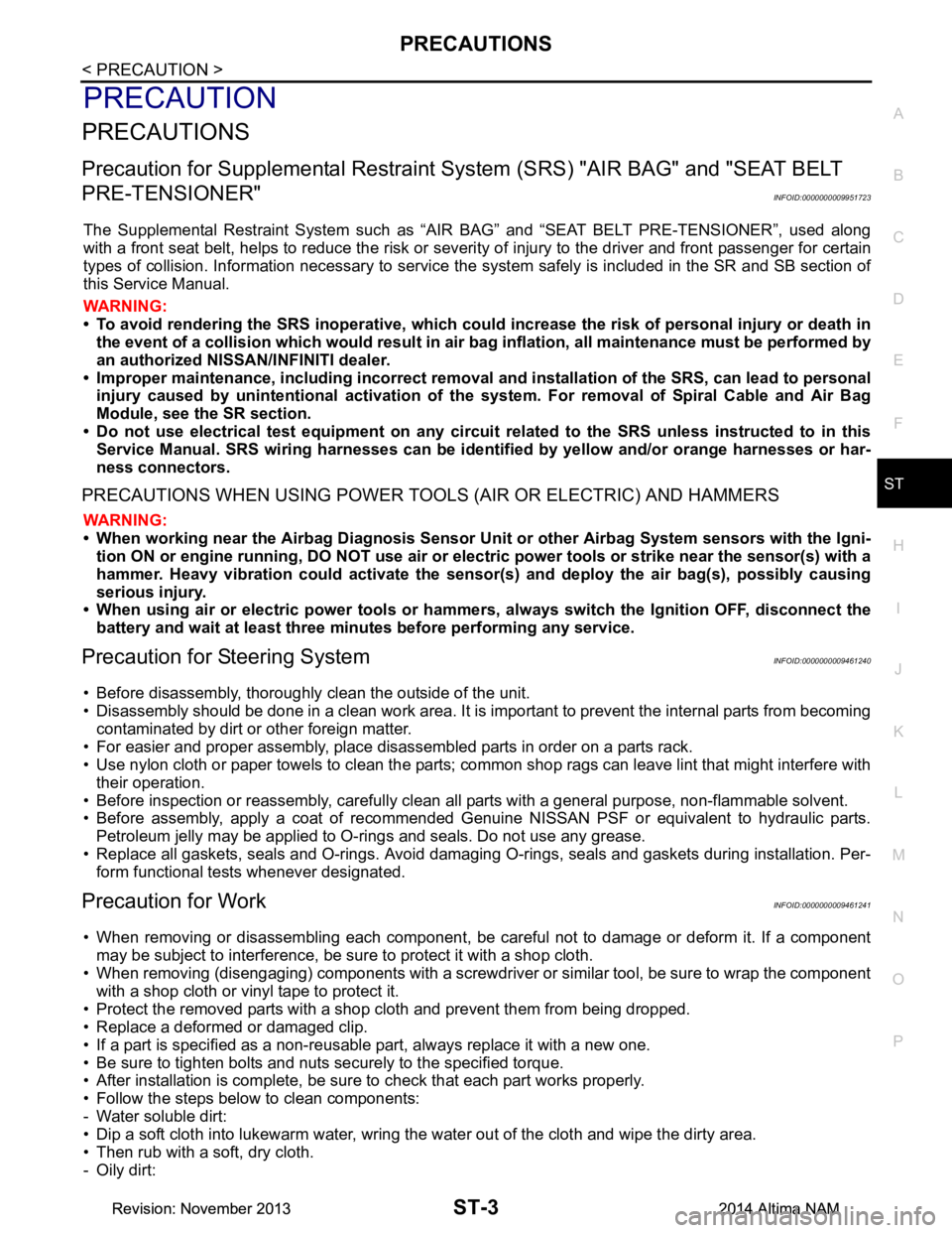
Precaution for Supplemental Restraint System (SRS) "AIR BAG" and "SEAT BELT
PRE-TENSIONER"
INFOID:0000000009951723
The Supplemental Restraint System such as “A IR BAG” and “SEAT BELT PRE-TENSIONER”, used along
with a front seat belt, helps to reduce the risk or severi ty of injury to the driver and front passenger for certain
types of collision. Information necessary to service t he system safely is included in the SR and SB section of
this Service Manual.
WARNING:
• To avoid rendering the SRS inoper ative, which could increase the risk of personal injury or death in
the event of a collision which would result in air bag inflation, all maintenance must be performed by
an authorized NISSAN/INFINITI dealer.
• Improper maintenance, including in correct removal and installation of the SRS, can lead to personal
injury caused by unintentional act ivation of the system. For removal of Spiral Cable and Air Bag
Module, see the SR section.
• Do not use electrical test equipm ent on any circuit related to the SRS unless instructed to in this
Service Manual. SRS wiring harnesses can be identi fied by yellow and/or orange harnesses or har-
ness connectors.
PRECAUTIONS WHEN USING POWER TOOLS (AIR OR ELECTRIC) AND HAMMERS
WARNING:
• When working near the Airbag Diagnosis Sensor Un it or other Airbag System sensors with the Igni-
tion ON or engine running, DO NOT use air or el ectric power tools or strike near the sensor(s) with a
hammer. Heavy vibration could activate the sensor( s) and deploy the air bag(s), possibly causing
serious injury.
• When using air or electric power tools or hammers , always switch the Ignition OFF, disconnect the
battery and wait at least three mi nutes before performing any service.
Precaution for Steering SystemINFOID:0000000009461240
• Before disassembly, thoroughly clean the outside of the unit.
• Disassembly should be done in a clean work area. It is im portant to prevent the internal parts from becoming
contaminated by dirt or other foreign matter.
• For easier and proper assembly, place disassembled parts in order on a parts rack.
• Use nylon cloth or paper towels to clean the parts; common shop rags can leave lint that might interfere with
their operation.
• Before inspection or reassembly, carefully clean al l parts with a general purpose, non-flammable solvent.
• Before assembly, apply a coat of recommended Genuine NISSAN PSF or equivalent to hydraulic parts.
Petroleum jelly may be applied to O-rings and seals. Do not use any grease.
• Replace all gaskets, seals and O-rings. Avoid damaging O-rings, seals and gaskets during installation. Per- form functional tests whenever designated.
Precaution for WorkINFOID:0000000009461241
• When removing or disassembling each component, be ca reful not to damage or deform it. If a component
may be subject to interference, be sure to protect it with a shop cloth.
• When removing (disengaging) components with a screwdriver or similar tool, be sure to wrap the component
with a shop cloth or vinyl tape to protect it.
• Protect the removed parts with a shop cloth and prevent them from being dropped.
• Replace a deformed or damaged clip.
• If a part is specified as a non-reusabl e part, always replace it with a new one.
• Be sure to tighten bolts and nuts securely to the specified torque.
• After installation is complete, be sure to check that each part works properly.
• Follow the steps below to clean components:
- Water soluble dirt:
• Dip a soft cloth into lukewarm water, wring the water out of the cloth and wipe the dirty area.
• Then rub with a soft, dry cloth.
-Oily dirt:
Revision: November 20132014 Altima NAMRevision: November 20132014 Altima NAM
Page 4118 of 4801
POWER STEERING FLUIDST-15
< BASIC INSPECTION >
C
D E
F
H I
J
K L
M A
B
ST
N
O P
POWER STEERING FLUID
InspectionINFOID:0000000009461251
FLUID LEVEL
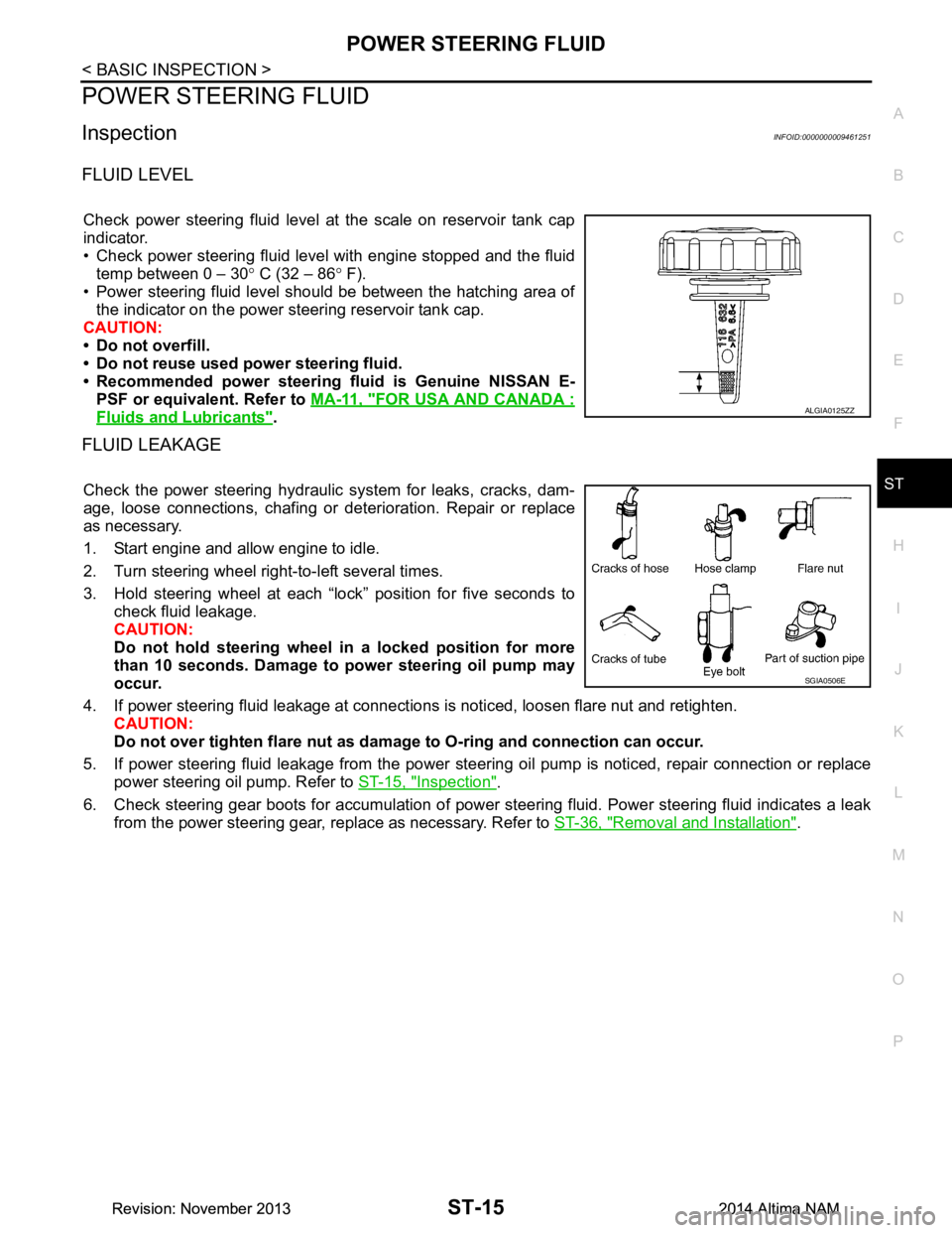
Check power steering fluid level at the scale on reservoir tank cap
indicator.
• Check power steering fluid level with engine stopped and the fluid temp between 0 – 30 ° C (32 – 86 ° F).
• Power steering fluid level should be between the hatching area of the indicator on the power steering reservoir tank cap.
CAUTION:
• Do not overfill.
• Do not reuse used power steering fluid.
• Recommended power steering fluid is Genuine NISSAN E-
PSF or equivalent. Refer to MA-11, "FOR USA AND CANADA :
Fluids and Lubricants".
FLUID LEAKAGE
Check the power steering hydraulic system for leaks, cracks, dam-
age, loose connections, chafing or det erioration. Repair or replace
as necessary.
1. Start engine and allow engine to idle.
2. Turn steering wheel right-to-left several times.
3. Hold steering wheel at each “lock” position for five seconds to check fluid leakage.
CAUTION:
Do not hold steering wheel in a locked position for more
than 10 seconds. Damage to power steering oil pump may
occur.
4. If power steering fluid leakage at connections is noticed, loosen flare nut and retighten.
CAUTION:
Do not over tighten flare nut as damage to O-ring and connection can occur.
5. If power steering fluid leakage from the power steer ing oil pump is noticed, repair connection or replace
power steering oil pump. Refer to ST-15, "Inspection"
.
6. Check steering gear boots for accumulation of power st eering fluid. Power steering fluid indicates a leak
from the power steering gear, replace as necessary. Refer to ST-36, "Removal and Installation"
.
ALGIA0125ZZ
SGIA0506E
Revision: November 20132014 Altima NAMRevision: November 20132014 Altima NAM
Page 4119 of 4801
ST-16
< BASIC INSPECTION >
STEERING WHEEL
STEERING WHEEL
InspectionINFOID:0000000009461252
CONDITION OF INSTALLATION
• Check installation condition of power steering gear assembly, front suspension, front drive shaft and steering
column.
• Check if movement exists when steering wheel is mo ved up and down, to the left and right and to the axial
direction.
• Verify that the power steering gear nuts are tightened to specification. Refer to ST-36, "Exploded View"
.
STEERING WHEEL PLAY
1. Turn tires straight ahead, start engine, then turn steer ing wheel to the left and right lightly. Measure steer-
ing wheel movement on the outer circumference of the steering wheel when it is turned to the point where
tires start moving.
NEUTRAL POSITION ON STEERING WHEEL
• Check neutral position on steering wheel after confirming that front wheel alignment is correct. Refer to FSU-
25, "Wheel Alignment (Unladen*1)".
1. Turn tires straight ahead, check if st eering wheel is in the neutral position.
2. If it is not in the neutral position, remo ve steering wheel and reinstall it correctly.
3. If the neutral position cannot be attained by repositi oning the steering wheel two teeth or less on steering
stem, loosen tie-rod lock nuts of power steering gear outer sockets, then adjust tie-rods by the same
amount in the opposite direction.
STEERING WHEEL TURNING FORCE
1. Park vehicle on a level, dry surface and set parking brake.
2. Start engine.
3. Bring power steering fluid up to operating temperature.
4. Verify that the tires are inflated to the specified pressure. Refer to WT-60, "Tire"
.
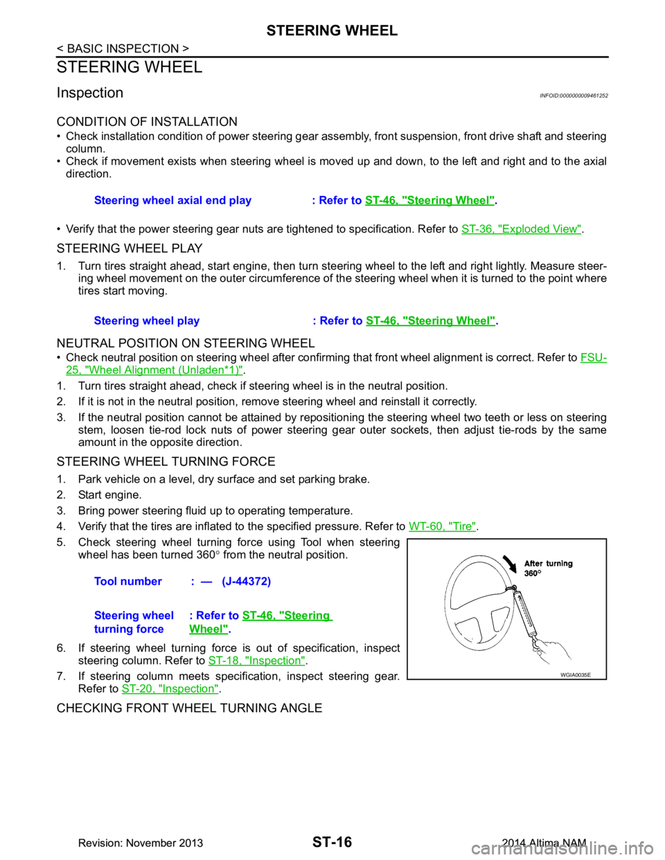
5. Check steering wheel turning force using Tool when steering wheel has been turned 360 ° from the neutral position.
6. If steering wheel turning force is out of specification, inspect steering column. Refer to ST-18, "Inspection"
.
7. If steering column meets specification, inspect steering gear. Refer to ST-20, "Inspection"
.
CHECKING FRONT WHEEL TURNING ANGLE
Steering wheel axial end play : Refer to ST-46, "Steering Wheel".
Steering wheel play : Refer to ST-46, "Steering Wheel"
.
Tool number : — (J-44372)
Steering wheel
turning force : Refer to
ST-46, "Steering
Wheel".
WGIA0035E
Revision: November 20132014 Altima NAMRevision: November 20132014 Altima NAM