2014 NISSAN TEANA check engine
[x] Cancel search: check enginePage 4120 of 4801
STEERING WHEELST-17
< BASIC INSPECTION >
C
D E
F
H I
J
K L
M A
B
ST
N
O P
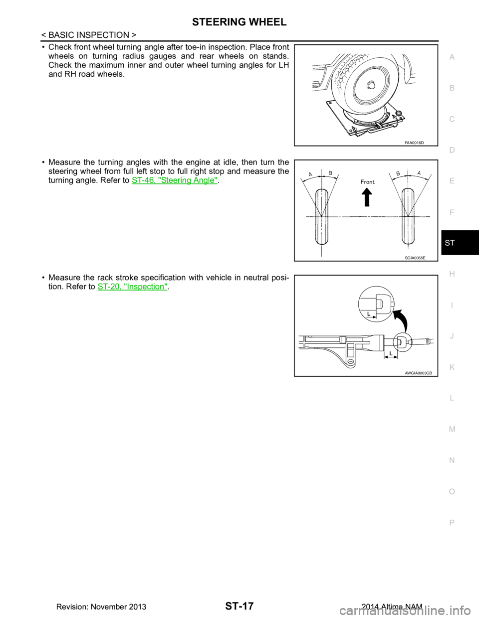
• Check front wheel turning angle after toe-in inspection. Place front wheels on turning radius gauges and rear wheels on stands.
Check the maximum inner and outer wheel turning angles for LH
and RH road wheels.
• Measure the turning angles with the engine at idle, then turn the steering wheel from full left stop to full right stop and measure the
turning angle. Refer to ST-46, "Steering Angle"
.
• Measure the rack stroke specification with vehicle in neutral posi- tion. Refer to ST-20, "Inspection"
.
FAA0016D
SGIA0055E
AWGIA0003GB
Revision: November 20132014 Altima NAMRevision: November 20132014 Altima NAM
Page 4133 of 4801
ST-30
< PERIODIC MAINTENANCE >
POWER STEERING FLUID
PERIODIC MAINTENANCE
POWER STEERING FLUID
Draining and RefillingINFOID:0000000009461266
DRAINING
1. Disconnect the high and low pressure piping from power steering gear.
2. Drain power steering fluid into a suitable container.
REFILLING
1. Fill power steering reservoir while checking power steering fluid level.
2. Bleed air from power steering hydraulic system. Refer to ST-30, "Air Bleeding Hydraulic System"
.
3. Check for power steering fluid leaks.
Air Bleeding Hydraulic SystemINFOID:0000000009461267
AIR BLEEDING HYDRAULIC SYSTEM
If air bleeding is not complete, excessive noise in the power steering oil pump will be present.
1. Make sure engine is off.
2. Turn the steering wheel from the full right stop pos ition and then to full left stop position several times.
Repeat until bubbles are no longer being generated in the reservoir.
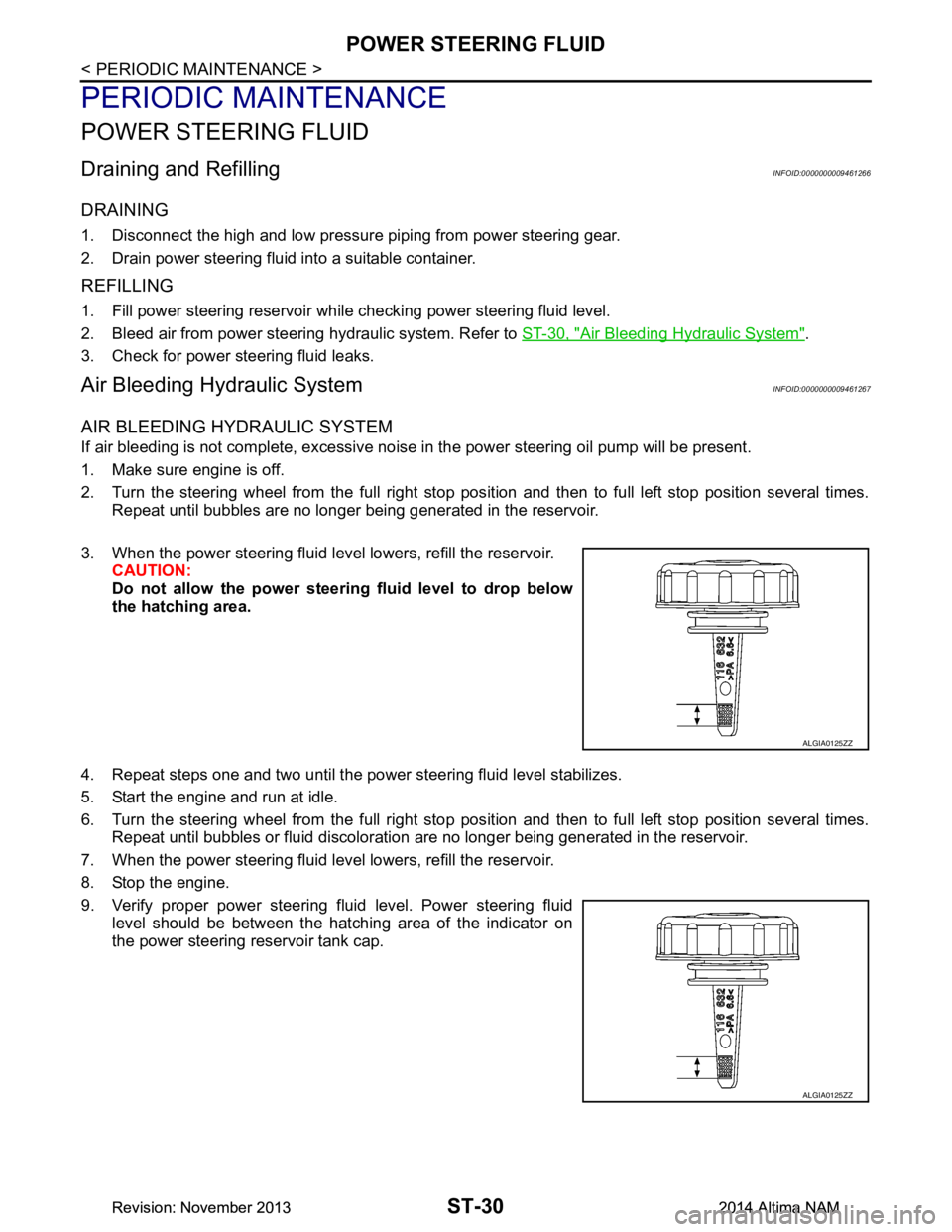
3. When the power steering fluid level lowers, refill the reservoir. CAUTION:
Do not allow the power steerin g fluid level to drop below
the hatching area.
4. Repeat steps one and two until the power steering fluid level stabilizes.
5. Start the engine and run at idle.
6. Turn the steering wheel from the full right stop pos ition and then to full left stop position several times.
Repeat until bubbles or fluid discoloration are no longer being generated in the reservoir.
7. When the power steering fluid level lowers, refill the reservoir.
8. Stop the engine.
9. Verify proper power steering fluid level. Power steering fluid level should be between the hatching area of the indicator on
the power steering reservoir tank cap.
ALGIA0125ZZ
ALGIA0125ZZ
Revision: November 20132014 Altima NAMRevision: November 20132014 Altima NAM
Page 4154 of 4801
PRECAUTIONSSTC-3
< PRECAUTION >
C
D E
F
H I
J
K L
M A
B
STC
N
O P
PRECAUTION
PRECAUTIONS
Precaution for Supplemental Restraint System (SRS) "AIR BAG" and "SEAT BELT
PRE-TENSIONER"
INFOID:0000000009951730
The Supplemental Restraint System such as “A IR BAG” and “SEAT BELT PRE-TENSIONER”, used along
with a front seat belt, helps to reduce the risk or severi ty of injury to the driver and front passenger for certain
types of collision. Information necessary to service t he system safely is included in the SR and SB section of
this Service Manual.
WARNING:
• To avoid rendering the SRS inoper ative, which could increase the risk of personal injury or death in
the event of a collision which would result in air bag inflation, all maintenance must be performed by
an authorized NISSAN/INFINITI dealer.
• Improper maintenance, including in correct removal and installation of the SRS, can lead to personal
injury caused by unintentional act ivation of the system. For removal of Spiral Cable and Air Bag
Module, see the SR section.
• Do not use electrical test equipm ent on any circuit related to the SRS unless instructed to in this
Service Manual. SRS wiring harnesses can be identi fied by yellow and/or orange harnesses or har-
ness connectors.
PRECAUTIONS WHEN USING POWER TOOLS (AIR OR ELECTRIC) AND HAMMERS
WARNING:
• When working near the Airbag Diagnosis Sensor Un it or other Airbag System sensors with the Igni-
tion ON or engine running, DO NOT use air or el ectric power tools or strike near the sensor(s) with a
hammer. Heavy vibration could activate the sensor( s) and deploy the air bag(s), possibly causing
serious injury.
• When using air or electric power tools or hammers , always switch the Ignition OFF, disconnect the
battery and wait at least three mi nutes before performing any service.
Service Notice and Precautions for Hydrau lic Pump Electric Power Steering System
INFOID:0000000009460340
• Check each tire for proper air pressure and size. Refer to WT-60, "Tire".
• Verify that the steering system components are G enuine NISSAN parts and have been installed properly.
• Check the steering column for loose mounting bolts.
• Check the steering gear assembly for loose mounting bolts. Check the inner sockets and outer sockets for
damage or wear. Inspect the boots and seals for leakage of power steering fluid.
• Verify proper wheel alignment. Refer to FSU-7, "Inspection and Adjustment"
.
• Check for any damage, wear, or modification to the suspension and body that would result in increased
weight or an improper wheelarch height. Refer to FSU-26, "Wheelarch Height (Unladen*
1)".
• Check for proper battery voltage.
• Verify that all power steering pump assembly connections are clean and fully seated.
• Verify that only Genuine NISSAN E-PSF is used. Use of any power steering fluid other than Genuine NIS-
SAN E-PSF will prevent the power st eering system from proper operation.
• An audible high pitch noise may be heard from the engine compartment when the steering wheel is oper-
ated, particularly at low speeds such as a parking lot maneuver. This condition is not a malfunction, rather
normal system operation. Steering at low speeds or parking lot maneuvers demands higher hydraulic assis-
tance, resulting in larger power st eering pump load and increased system noise.
• The power steering pump is electrically controlled by the power steering control module.
• Before connecting or disconnecting the power steeri ng control module harness connectors, turn ignition
switch “OFF” and disconnect battery ground cable. Batter y voltage is applied to power steering control mod-
ule even if ignition switch is turned “OFF”.
Revision: November 20132014 Altima NAMRevision: November 20132014 Altima NAM
Page 4159 of 4801
STC-8
< SYSTEM DESCRIPTION >
SYSTEM
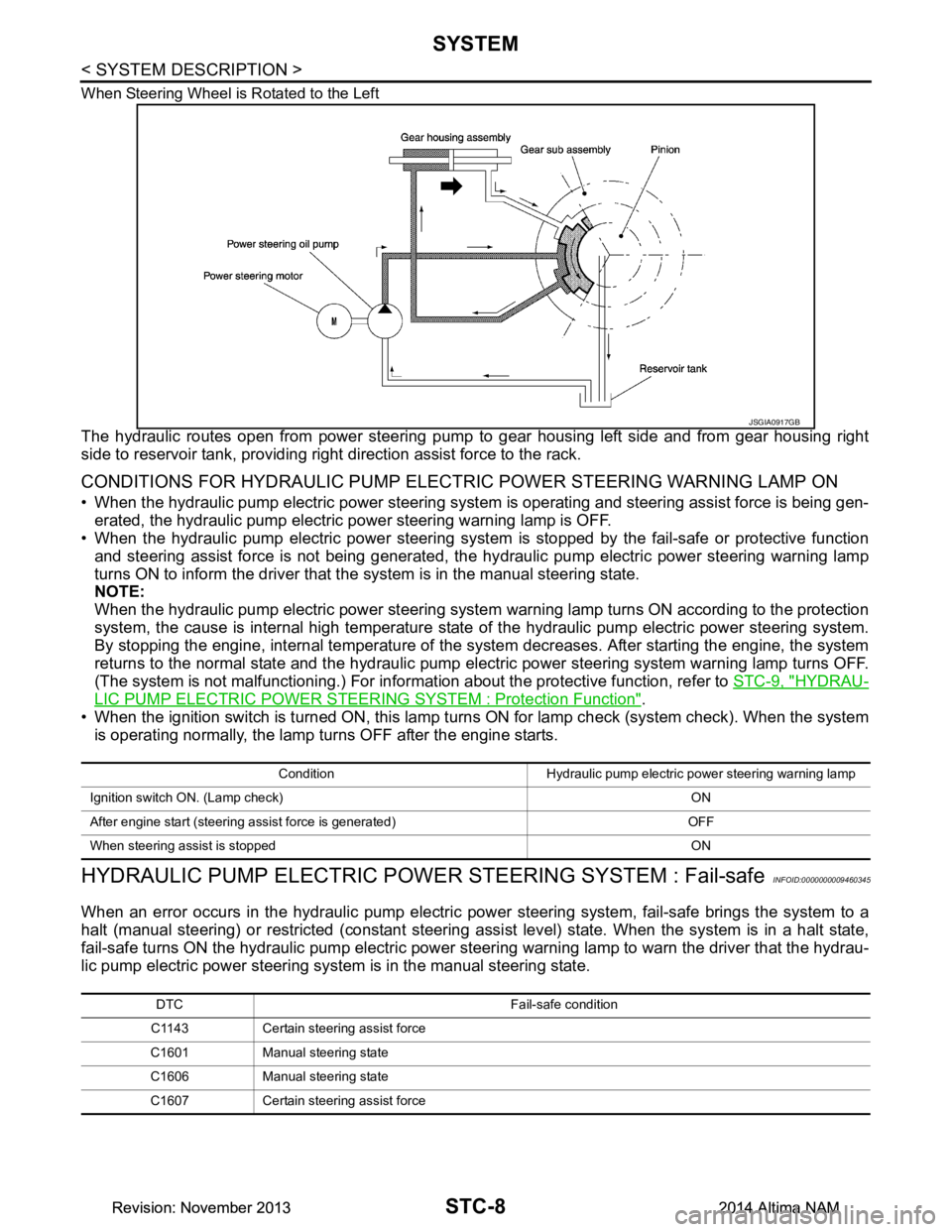
When Steering Wheel is Rotated to the Left
The hydraulic routes open from power steering pump to gear housing left side and from gear housing right
side to reservoir tank, providing right direction assist force to the rack.
CONDITIONS FOR HYDRAULIC PUMP ELECTR IC POWER STEERING WARNING LAMP ON
• When the hydraulic pump electric power steering syst em is operating and steering assist force is being gen-
erated, the hydraulic pump electric power steering warning lamp is OFF.
• When the hydraulic pump electric power steering system is stopped by the fail-safe or protective function
and steering assist force is not being generated, the hy draulic pump electric power steering warning lamp
turns ON to inform the driver that t he system is in the manual steering state.
NOTE:
When the hydraulic pump electric power steering system warning lamp turns ON according to the protection
system, the cause is internal high temperature state of the hydraulic pump electric power steering system.
By stopping the engine, internal temperature of the s ystem decreases. After starting the engine, the system
returns to the normal state and the hydraulic pump elec tric power steering system warning lamp turns OFF.
(The system is not malfunctioning.) For informat ion about the protective function, refer to STC-9, "HYDRAU-
LIC PUMP ELECTRIC POWER STEERING SYSTEM : Protection Function".
• When the ignition switch is turned ON, this lamp turn s ON for lamp check (system check). When the system
is operating normally, the lamp turns OFF after the engine starts.
HYDRAULIC PUMP ELECTRIC POWE R STEERING SYSTEM : Fail-safeINFOID:0000000009460345
When an error occurs in the hydraulic pump electric pow er steering system, fail-safe brings the system to a
halt (manual steering) or restricted (constant steering assi st level) state. When the system is in a halt state,
fail-safe turns ON the hydraulic pump electric power steer ing warning lamp to warn the driver that the hydrau-
lic pump electric power steering system is in the manual steering state.
JSGIA0917GB
Condition Hydraulic pump electric power steering warning lamp
Ignition switch ON. (Lamp check) ON
After engine start (steering assist force is generated) OFF
When steering assist is stopped ON
DTC Fail-safe condition
C1143 Certain steering assist force
C1601 Manual steering state
C1606 Manual steering state
C1607 Certain steering assist force
Revision: November 20132014 Altima NAMRevision: November 20132014 Altima NAM
Page 4171 of 4801

STC-20
< BASIC INSPECTION >
DIAGNOSIS AND REPAIR WORK FLOW
YES >> GO TO 6.
NO >> Check harness and connectors based on the information obtained by interview.
6.REPAIR OR REPLACE THE MALFUNCTIONING COMPONENTS.
• Repair or replace the malfunctioning components.
• Reconnect part or connector after repairing or replacing.
• When DTC is detected, erase self-diagnostic results for “EPS”.
>> GO TO 8.
7.IDENTIFY THE MALFUNCTIONING SYSTEM BY SYMPTOM DIAGNOSIS
Estimate the malfunctioning system based on symptom diagnosis and perform inspection.
Can the malfunctioning system be identified?
YES >> GO TO 8.
NO >> Check harness and connectors based on the information obtained by interview.
8.FINAL CHECK
With CONSULT
1. Check the reference value for power steering control module.
2. Recheck the symptom and check that sympto m is not reproduced on the same conditions.
Is the symptom reproduced?
YES >> GO TO 3.
NO >> Inspection End.
Diagnostic Work SheetINFOID:0000000009460355
Description
• In general, customers have their own criteria for a pr oblem. Therefore, it is important to understand the
symptom and status well enough by asking the customer about his/her concerns carefully. To systemize all
the information for the diagnosis, prepare the interview sheet referring to the interview points.
• In some cases, multiple conditions that appear simultaneously may cause a DTC to be detected.
Interview sheet sample
Interview sheet
Customer
name MR/MSRegistration
number Initial year
registration
Vehicle type VIN
Storage date Engine Mileage km (Mile)
Symptom �†
The steering wheel position (center) is in the wrong position.
�† Warning lamp turns on.
�† Noise �†Vibration
�† Others
( )
First occurrence �†Recently �†Others ( )
Frequency of occurrence �†Always �†Under a certain conditions of �†Sometimes (time(s)/day)
Climate con-
ditions �†
Irrelevant
Weather �†Fine �†Cloud �†Rain �†Snow �†Others ( )
Temperature �†Hot �†Warm �†Cool �†Cold �†Temperature [Approx. °C ( °F)]
Relative humidity �†High �†Moderate �†Low
Road conditions �†
Urban area �†Suburb area �†High way
�† Mountain road (uphill or down hill) �†Rough road
Revision: November 20132014 Altima NAMRevision: November 20132014 Altima NAM
Page 4174 of 4801
C1601 BATTERY POWER SUPPLYSTC-23
< DTC/CIRCUIT DIAGNOSIS >
C
D E
F
H I
J
K L
M A
B
STC
N
O P
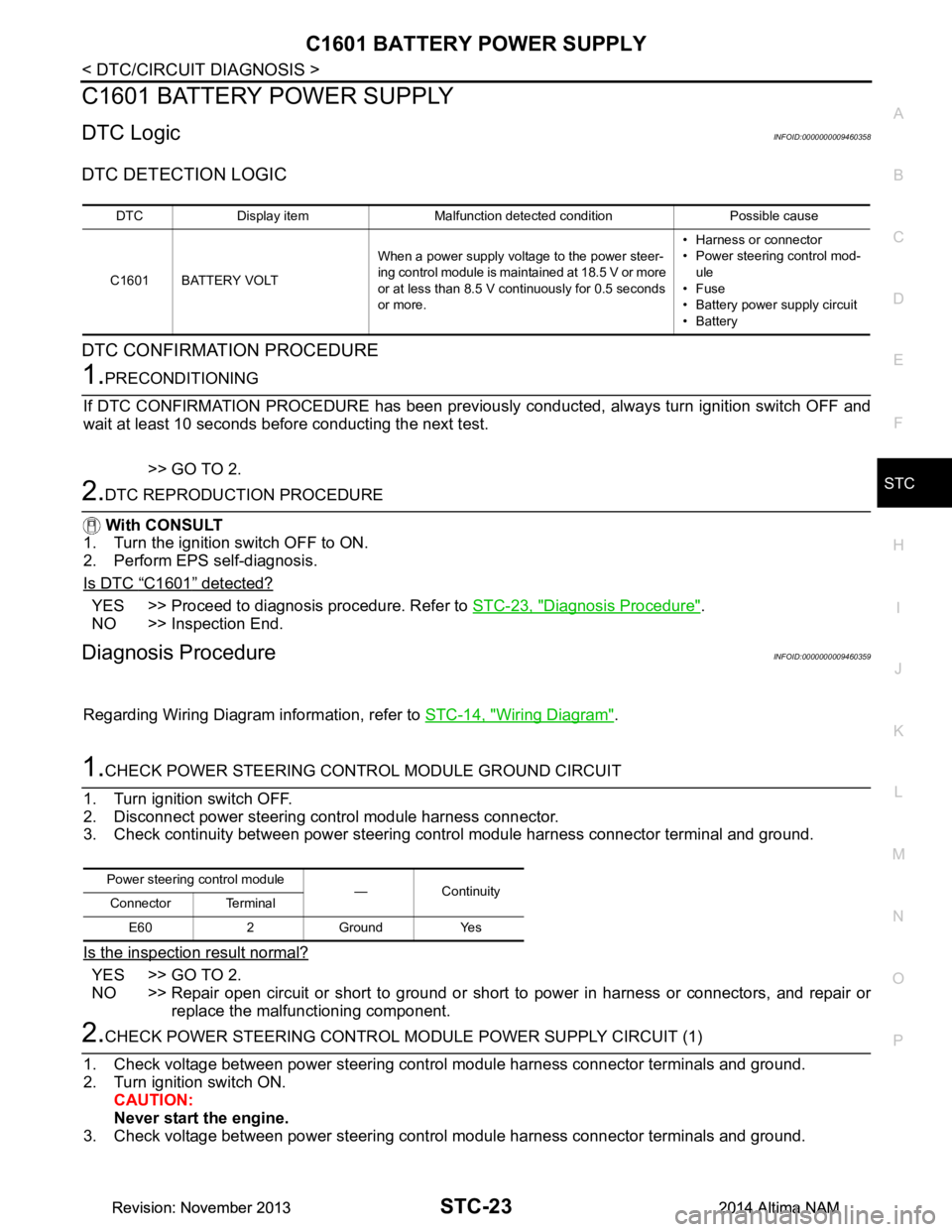
C1601 BATTERY POWER SUPPLY
DTC LogicINFOID:0000000009460358
DTC DETECTION LOGIC
DTC CONFIRMATION PROCEDURE
1.PRECONDITIONING
If DTC CONFIRMATION PROCEDURE has been previously conducted, always turn ignition switch OFF and
wait at least 10 seconds before conducting the next test.
>> GO TO 2.
2.DTC REPRODUCTION PROCEDURE
With CONSULT
1. Turn the ignition switch OFF to ON.
2. Perform EPS self-diagnosis.
Is DTC
“C1601” detected?
YES >> Proceed to diagnosis procedure. Refer to STC-23, "Diagnosis Procedure".
NO >> Inspection End.
Diagnosis ProcedureINFOID:0000000009460359
Regarding Wiring Diagram information, refer to STC-14, "Wiring Diagram".
1.CHECK POWER STEERING CONTROL MODULE GROUND CIRCUIT
1. Turn ignition switch OFF.
2. Disconnect power steering control module harness connector.
3. Check continuity between power steering control module harness connector terminal and ground.
Is the inspection result normal?
YES >> GO TO 2.
NO >> Repair open circuit or short to ground or short to power in harness or connectors, and repair or
replace the malfunctioning component.
2.CHECK POWER STEERING CONTROL MO DULE POWER SUPPLY CIRCUIT (1)
1. Check voltage between power steering control module harness connector terminals and ground.
2. Turn ignition switch ON. CAUTION:
Never start the engine.
3. Check voltage between power steering control module harness connector terminals and ground.
DTC Display item Malfunction detected condition Possible cause
C1601 BATTERY VOLT When a power supply voltage to the power steer-
ing control module is maintained at 18.5 V or more
or at less than 8.5 V continuously for 0.5 seconds
or more. • Harness or connector
• Power steering control mod-
ule
•Fuse
• Battery power supply circuit
•Battery
Power steering control module
—Continuity
Connector Terminal
E60 2 Ground Yes
Revision: November 20132014 Altima NAMRevision: November 20132014 Altima NAM
Page 4175 of 4801
STC-24
< DTC/CIRCUIT DIAGNOSIS >
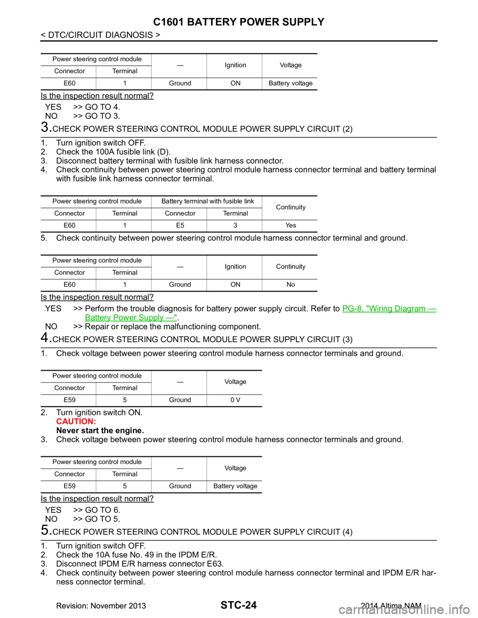
C1601 BATTERY POWER SUPPLY
Is the inspection result normal?
YES >> GO TO 4.
NO >> GO TO 3.
3.CHECK POWER STEERING CONTROL MODULE POWER SUPPLY CIRCUIT (2)
1. Turn ignition switch OFF.
2. Check the 100A fusible link (D).
3. Disconnect battery terminal with fusible link harness connector.
4. Check continuity between power steering contro l module harness connector terminal and battery terminal
with fusible link harness connector terminal.
5. Check continuity between power steering c ontrol module harness connector terminal and ground.
Is the inspection result normal?
YES >> Perform the trouble diagnosis for battery power supply circuit. Refer to PG-8, "Wiring Diagram —
Battery Power Supply —".
NO >> Repair or replace the malfunctioning component.
4.CHECK POWER STEERING CONTROL MODULE POWER SUPPLY CIRCUIT (3)
1. Check voltage between power steering control module harness connector terminals and ground.
2. Turn ignition switch ON. CAUTION:
Never start the engine.
3. Check voltage between power steering control module harness connector terminals and ground.
Is the inspection result normal?
YES >> GO TO 6.
NO >> GO TO 5.
5.CHECK POWER STEERING CONTROL MODULE POWER SUPPLY CIRCUIT (4)
1. Turn ignition switch OFF.
2. Check the 10A fuse No. 49 in the IPDM E/R.
3. Disconnect IPDM E/R harness connector E63.
4. Check continuity between power steering control module harness connector terminal and IPDM E/R har-
ness connector terminal.
Power steering control module — Ignition Voltage
Connector Terminal
E60 1 Ground ON Battery voltage
Power steering control module Batte ry terminal with fusible link
Continuity
Connector Terminal Connector Terminal
E60 1 E5 3 Yes
Power steering control module — Ignition Continuity
Connector Terminal
E60 1 Ground ON No
Power steering control module —Voltage
Connector Terminal
E59 5 Ground 0 V
Power steering control module —Voltage
Connector Terminal
E59 5 Ground Battery voltage
Revision: November 20132014 Altima NAMRevision: November 20132014 Altima NAM
Page 4182 of 4801
HYDRAULIC PUMP ELECTRIC POWER STEERING WARNING LAMP
STC-31
< DTC/CIRCUIT DIAGNOSIS >
C
D E
F
H I
J
K L
M A
B
STC
N
O P
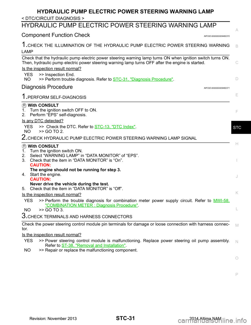
HYDRAULIC PUMP ELECTRIC PO WER STEERING WARNING LAMP
Component Function CheckINFOID:0000000009460370
1.CHECK THE ILLUMINATION OF THE HYDRAULIC PUMP ELECTRIC POWER STEERING WARNING
LAMP
Check that the hydraulic pump electric power steering warning lamp turns ON when ignition switch turns ON.
Then, hydraulic pump electric power steering warn ing lamp turns OFF after the engine is started.
Is the inspection result normal?
YES >> Inspection End.
NO >> Perform trouble diagnosis. Refer to STC-31, "Diagnosis Procedure"
.
Diagnosis ProcedureINFOID:0000000009460371
1.PERFORM SELF-DIAGNOSIS
With CONSULT
1. Turn the ignition switch OFF to ON.
2. Perform “EPS” self-diagnosis.
Is any DTC detected?
YES >> Check the DTC. Refer to STC-13, "DTC Index".
NO >> GO TO 2.
2.CHECK HYDRAULIC PUMP ELECTRIC PO WER STEERING WARNING LAMP SIGNAL
With CONSULT
1. Turn the ignition switch ON.
2. Select “WARNING LAMP” in “DATA MONITOR” of “EPS”.
3. Check that the item in “DATA MONITOR” is “On”. CAUTION:
The engine should not be running for step 3.
4. Start the engine. CAUTION:
Never drive the vehicle during the test.
5. Check that the item in “DATA MONITOR” is “Off”.
Is the inspection result normal?
YES >> Perform the trouble diagnosis for combinat ion meter power supply circuit. Refer to MWI-58,
"COMBINATION METER : Diagnosis Procedure".
NO >> GO TO 3.
3.CHECK TERMINALS AND HARNESS CONNECTORS
Check the power steering control module pin terminal s for damage or loose connection with harness connec-
tor.
Is the inspection result normal?
YES >> Power steering control module is malfuncti oning. Replace power steering oil pump assembly.
Refer to ST-38, "Removal and Installation"
.
NO >> Repair or replace the malfunctioning component.
Revision: November 20132014 Altima NAMRevision: November 20132014 Altima NAM