2014 NISSAN TEANA check engine
[x] Cancel search: check enginePage 4184 of 4801
HYDRAULIC PUMP ELECTRIC POWER STEERING WARNING LAMP DOES
NOT TURN OFF
STC-33
< SYMPTOM DIAGNOSIS >
C
D E
F
H I
J
K L
M A
B
STC
N
O P
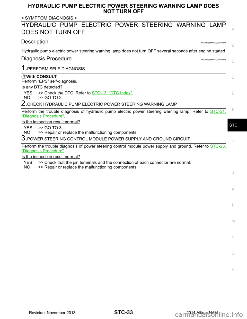
HYDRAULIC PUMP ELECTRIC POWER STEERING WARNING LAMP
DOES NOT TURN OFF
DescriptionINFOID:0000000009460374
Hydraulic pump electric power steering warning lamp does not turn OFF several seconds after engine started
Diagnosis ProcedureINFOID:0000000009460375
1.PERFORM SELF-DIAGNOSIS
With CONSULT
Perform “EPS” self-diagnosis.
Is any DTC detected?
YES >> Check the DTC. Refer to STC-13, "DTC Index".
NO >> GO TO 2.
2.CHECK HYDRAULIC PUMP ELECTRIC POWER STEERING WARNING LAMP
Perform the trouble diagnosis of hydraulic pump el ectric power steering warning lamp. Refer to STC-31,
"Diagnosis Procedure".
Is the inspection result normal?
YES >> GO TO 3.
NO >> Repair or replace the malfunctioning components.
3.POWER STEERING CONT ROL MODULE POWER SUPPLY AND GROUND CIRCUIT
Perform the trouble diagnosis of power steering control module power supply and ground. Refer to STC-23,
"Diagnosis Procedure".
Is the inspection result normal?
YES >> Check that the pin terminals and t he connection of each connector are normal.
NO >> Repair or replace the malfunctioning components.
Revision: November 20132014 Altima NAMRevision: November 20132014 Altima NAM
Page 4185 of 4801
STC-34
< SYMPTOM DIAGNOSIS >
STEERING WHEEL TURNING FORCE IS HEAVY OR LIGHT
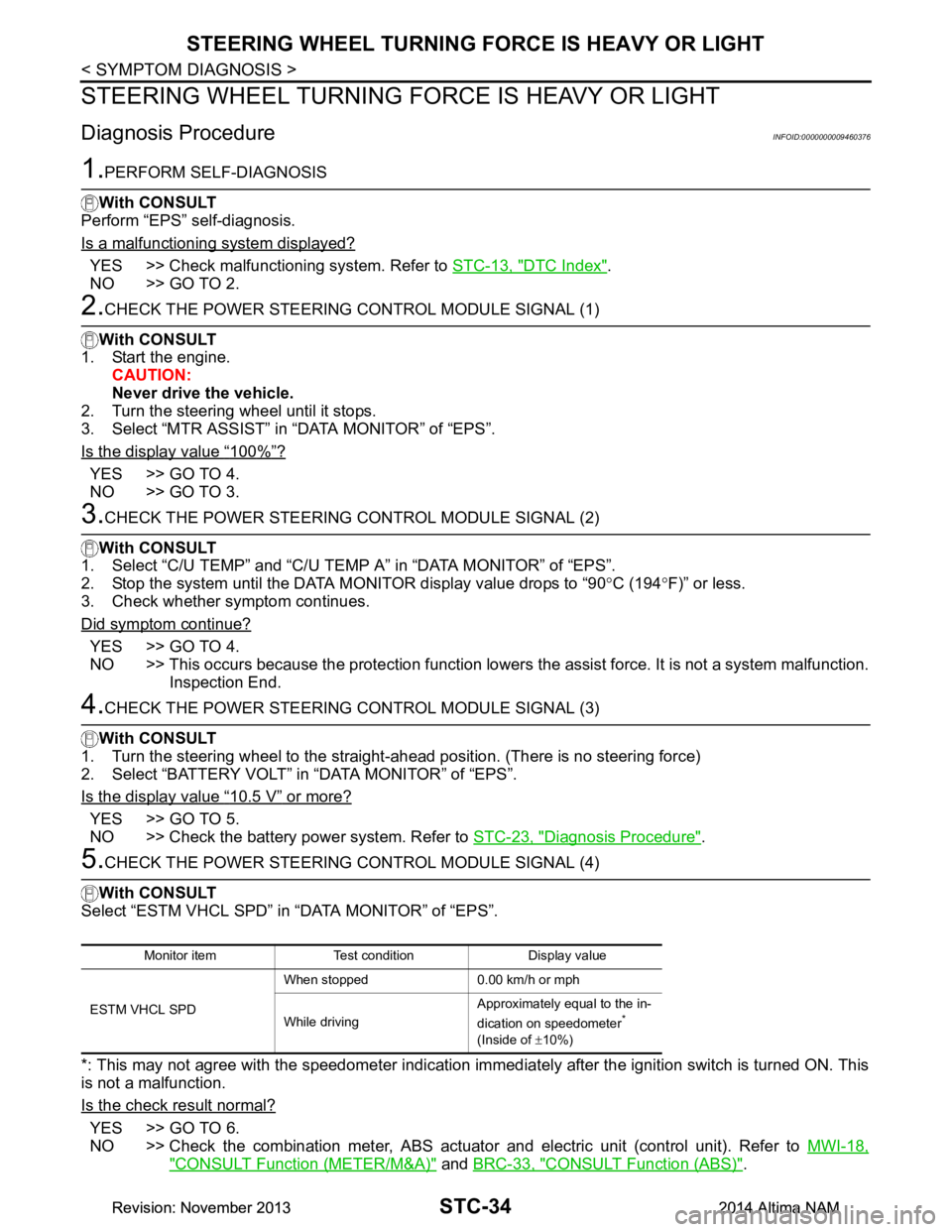
STEERING WHEEL TURNING FORCE IS HEAVY OR LIGHT
Diagnosis ProcedureINFOID:0000000009460376
1.PERFORM SELF-DIAGNOSIS
With CONSULT
Perform “EPS” self-diagnosis.
Is a malfunctioning system displayed?
YES >> Check malfunctioning system. Refer to STC-13, "DTC Index".
NO >> GO TO 2.
2.CHECK THE POWER STEERING CONTROL MODULE SIGNAL (1)
With CONSULT
1. Start the engine. CAUTION:
Never drive the vehicle.
2. Turn the steering wheel until it stops.
3. Select “MTR ASSIST” in “DATA MONITOR” of “EPS”.
Is the display value
“100%”?
YES >> GO TO 4.
NO >> GO TO 3.
3.CHECK THE POWER STEERING CONTROL MODULE SIGNAL (2)
With CONSULT
1. Select “C/U TEMP” and “C/U TEMP A” in “DATA MONITOR” of “EPS”.
2. Stop the system until the DATA MONITOR display value drops to “90 °C (194 °F)” or less.
3. Check whether symptom continues.
Did symptom continue?
YES >> GO TO 4.
NO >> This occurs because the protection function lowers the assist force. It is not a system malfunction.
Inspection End.
4.CHECK THE POWER STEERING CONTROL MODULE SIGNAL (3)
With CONSULT
1. Turn the steering wheel to the straight -ahead position. (There is no steering force)
2. Select “BATTERY VOLT” in “DATA MONITOR” of “EPS”.
Is the display value
“10.5 V” or more?
YES >> GO TO 5.
NO >> Check the battery power system. Refer to STC-23, "Diagnosis Procedure"
.
5.CHECK THE POWER STEERING CONTROL MODULE SIGNAL (4)
With CONSULT
Select “ESTM VHCL SPD” in “DATA MONITOR” of “EPS”.
*: This may not agree with the speedometer indication imm ediately after the ignition switch is turned ON. This
is not a malfunction.
Is the check result normal?
YES >> GO TO 6.
NO >> Check the combination meter, ABS actuator and electric unit (control unit). Refer to MWI-18,
"CONSULT Function (METER/M&A)" and BRC-33, "CONSULT Function (ABS)".
Monitor item Test condition Display value
ESTM VHCL SPD When stopped 0.00 km/h or mph
While driving Approximately equal to the in-
dication on speedometer
*
(Inside of ±10%)
Revision: November 20132014 Altima NAMRevision: November 20132014 Altima NAM
Page 4186 of 4801
STEERING WHEEL TURNING FORCE IS HEAVY OR LIGHTSTC-35
< SYMPTOM DIAGNOSIS >
C
D E
F
H I
J
K L
M A
B
STC
N
O P
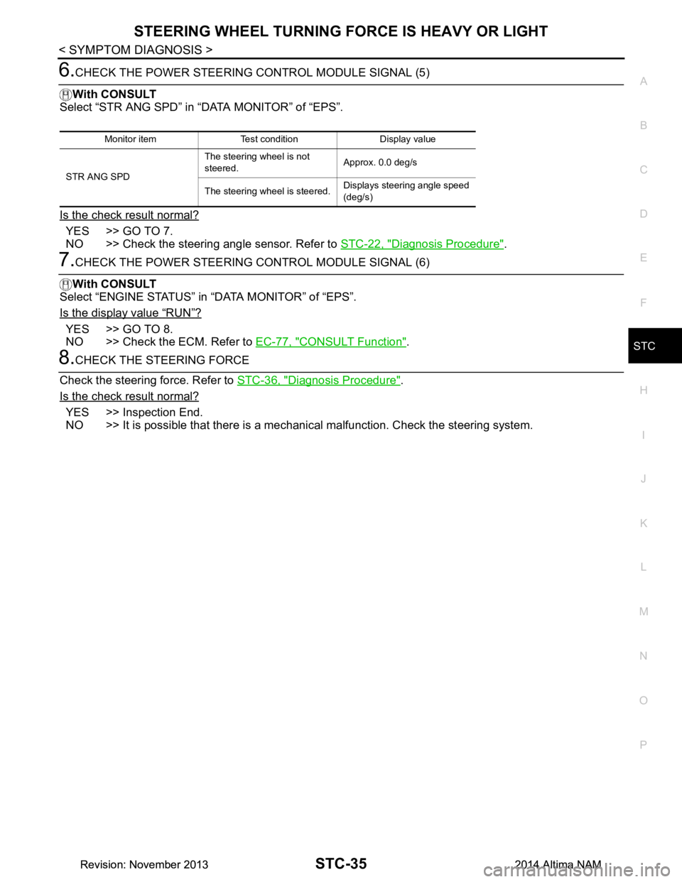
6.CHECK THE POWER STEERING CONTROL MODULE SIGNAL (5)
With CONSULT
Select “STR ANG SPD” in “DATA MONITOR” of “EPS”.
Is the check result normal?
YES >> GO TO 7.
NO >> Check the steering angle sensor. Refer to STC-22, "Diagnosis Procedure"
.
7.CHECK THE POWER STEERING CONTROL MODULE SIGNAL (6)
With CONSULT
Select “ENGINE STATUS” in “DATA MONITOR” of “EPS”.
Is the display value
“RUN”?
YES >> GO TO 8.
NO >> Check the ECM. Refer to EC-77, "CONSULT Function"
.
8.CHECK THE STEERING FORCE
Check the steering force. Refer to STC-36, "Diagnosis Procedure"
.
Is the check result normal?
YES >> Inspection End.
NO >> It is possible that there is a mechani cal malfunction. Check the steering system.
Monitor item Test condition Display value
STR ANG SPD The steering wheel is not
steered. Approx. 0.0 deg/s
The steering wheel is steered. Displays steering angle speed
(deg/s)
Revision: November 20132014 Altima NAMRevision: November 20132014 Altima NAM
Page 4187 of 4801
STC-36
< SYMPTOM DIAGNOSIS >
UNBALANCE STEERING WHEEL TURNING FORCE AND RETURN BETWEEN
RIGHT AND LEFT
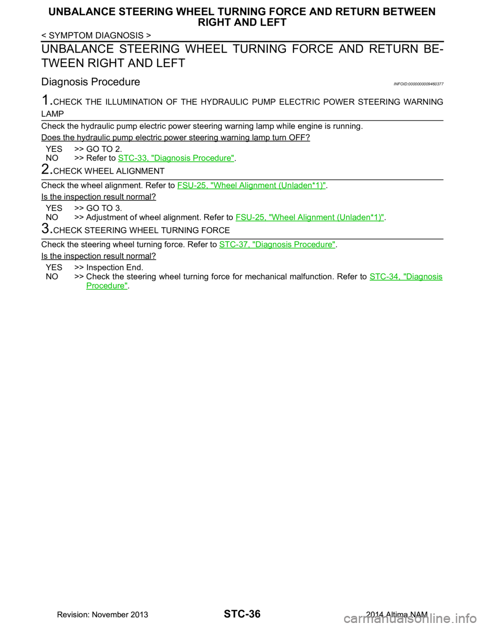
UNBALANCE STEERING WHEEL TU RNING FORCE AND RETURN BE-
TWEEN RIGHT AND LEFT
Diagnosis ProcedureINFOID:0000000009460377
1.CHECK THE ILLUMINATION OF THE HYDRAULIC PUMP ELECTRIC POWER STEERING WARNING
LAMP
Check the hydraulic pump electric power steering warning lamp while engine is running.
Does the hydraulic pump electric power steering warning lamp turn OFF?
YES >> GO TO 2.
NO >> Refer to STC-33, "Diagnosis Procedure"
.
2.CHECK WHEEL ALIGNMENT
Check the wheel alignment. Refer to FSU-25, "Wheel Alignment (Unladen*
1)".
Is the inspection result normal?
YES >> GO TO 3.
NO >> Adjustment of wheel alignment. Refer to FSU-25, "Wheel Alignment (Unladen*
1)".
3.CHECK STEERING WHEEL TURNING FORCE
Check the steering wheel turning force. Refer to STC-37, "Diagnosis Procedure"
.
Is the inspection result normal?
YES >> Inspection End.
NO >> Check the steering wheel turning force for mechanical malfunction. Refer to STC-34, "Diagnosis
Procedure".
Revision: November 20132014 Altima NAMRevision: November 20132014 Altima NAM
Page 4188 of 4801
UNBALANCE STEERING WHEEL TURNING FORCE (TORQUE VARIATION)
STC-37
< SYMPTOM DIAGNOSIS >
C
D E
F
H I
J
K L
M A
B
STC
N
O P
UNBALANCE STEERING WHEEL TU RNING FORCE (TORQUE VARIA-
TION)
Diagnosis ProcedureINFOID:0000000009460378
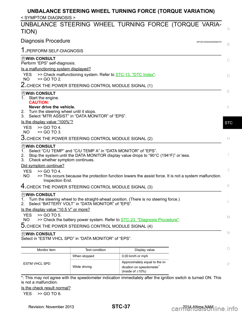
1.PERFORM SELF-DIAGNOSIS
With CONSULT
Perform “EPS” self-diagnosis.
Is a malfunctioning system displayed?
YES >> Check malfunctioning system. Refer to STC-13, "DTC Index".
NO >> GO TO 2.
2.CHECK THE POWER STEERING CONTROL MODULE SIGNAL (1)
With CONSULT
1. Start the engine. CAUTION:
Never drive the vehicle.
2. Turn the steering wheel until it stops.
3. Select “MTR ASSIST” in “DATA MONITOR” of “EPS”.
Is the display value
“100%”?
YES >> GO TO 4.
NO >> GO TO 3.
3.CHECK THE POWER STEERING CONTROL MODULE SIGNAL (2)
With CONSULT
1. Select “C/U TEMP” and “C/U TEMP A” in “DATA MONITOR” of “EPS”.
2. Stop the system until the DATA MONITOR display value drops to “90 °C (194 °F)” or less.
3. Check whether symptom continues.
Did symptom continue?
YES >> GO TO 4.
NO >> This occurs because the protection function lowers the assist force. It is not a system malfunction.
Inspection End.
4.CHECK THE POWER STEERING CONTROL MODULE SIGNAL (3)
With CONSULT
1. Turn the steering wheel to the straight -ahead position. (There is no steering force.)
2. Select “BATTERY VOLT” in “DATA MONITOR” of “EPS”.
Is the display value
“10.5 V” or more?
YES >> GO TO 5.
NO >> Check the battery power system. Refer to STC-23, "Diagnosis Procedure"
.
5.CHECK THE POWER STEERING CONTROL MODULE SIGNAL (4)
With CONSULT
Select in “ESTM VHCL SPD” in “DATA MONITOR” of “EPS”.
*: This may not agree with the speedometer indication immediately after the ignition switch is turned ON. This
is not a malfunction.
Is the check result normal?
YES >> GO TO 6.
Monitor item Test condition Display value
ESTM VHCL SPD When stopped 0.00 km/h or mph
While driving Approximately equal to the in-
dication on speedometer
*
(Inside of ±10%)
Revision: November 20132014 Altima NAMRevision: November 20132014 Altima NAM
Page 4189 of 4801
STC-38
< SYMPTOM DIAGNOSIS >
UNBALANCE STEERING WHEEL TURNING FORCE (TORQUE VARIATION)
NO >> Check the combination meter, ABS actuator and electric unit (control unit). Refer to MWI-18,
"CONSULT Function (METER/M&A)" and BRC-33, "CONSULT Function (ABS)".
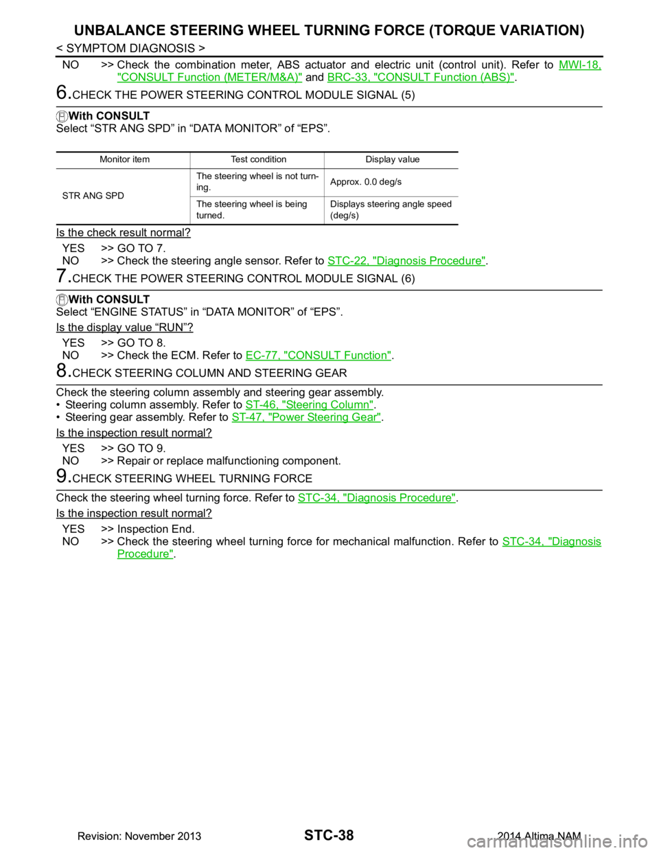
6.CHECK THE POWER STEERING CONTROL MODULE SIGNAL (5)
With CONSULT
Select “STR ANG SPD” in “DATA MONITOR” of “EPS”.
Is the check result normal?
YES >> GO TO 7.
NO >> Check the steering angle sensor. Refer to STC-22, "Diagnosis Procedure"
.
7.CHECK THE POWER STEERING CONTROL MODULE SIGNAL (6)
With CONSULT
Select “ENGINE STATUS” in “DATA MONITOR” of “EPS”.
Is the display value
“RUN”?
YES >> GO TO 8.
NO >> Check the ECM. Refer to EC-77, "CONSULT Function"
.
8.CHECK STEERING COLUMN AND STEERING GEAR
Check the steering column assembly and steering gear assembly.
• Steering column assembly. Refer to ST-46, "Steering Column"
.
• Steering gear assembly. Refer to ST-47, "Power Steering Gear"
.
Is the inspection result normal?
YES >> GO TO 9.
NO >> Repair or replace malfunctioning component.
9.CHECK STEERING WHEEL TURNING FORCE
Check the steering wheel turning force. Refer to STC-34, "Diagnosis Procedure"
.
Is the inspection result normal?
YES >> Inspection End.
NO >> Check the steering wheel turning force for mechanical malfunction. Refer to STC-34, "Diagnosis
Procedure".
Monitor item Test condition Display value
STR ANG SPD The steering wheel is not turn-
ing. Approx. 0.0 deg/s
The steering wheel is being
turned. Displays steering angle speed
(deg/s)
Revision: November 20132014 Altima NAMRevision: November 20132014 Altima NAM
Page 4204 of 4801

STR-14
< BASIC INSPECTION >
DIAGNOSIS AND REPAIR WORKFLOW
Perform the starting system test with Multitasking battery and electrical diagnostic station GR8-1200 NI. For
details and operating instructions, refer to diagnostic station Instruction Manual.
Te s t r e s u l t
CRANKING NORMAL>>GO TO 2.
LOW VOLTAGE>>GO TO 5.
CHARGE BATTERY>>Perform the slow battery charging procedure. (Initial rate of charge is 10A for 12
hours.) Perform battery test again. Refer to diagnostic station instruction manual.
REPLACE BATTERY>>Before replacing battery, clean t he battery cable clamps and battery posts. Perform
battery test again. Refer to diagnostic station instruction manual. If second test result is
“REPLACE BATTERY”, then do so. Perform battery test again to confirm repair.
2.CRANKING CHECK
Check that the starter motor operates properly.
Does the engine crank normally?
YES >> GO TO 3.
NO >> GO TO 4.
3.ENGINE START CHECK
Check that the engine starts.
Does the engine start?
YES >> Inspection End.
NO >> Perform further diagnosis of engine mechanical or engine control system. Refer to EM and EC sections. Once resolved, perform battery test again.
4.STARTER MOTOR ACTIVATION
Check that the starter motor operates.
Does the starter motor turn?
YES >> Check ring gear and starter motor drive pinion. Once resolved, perform battery test again.
NO >> GO TO 7.
5.COMPARISON BETWEEN ENGINE COOLANT AND CRANKING VOLTAGE
Compare the engine coolant temperature and verify the cranking voltage is within specifications.
Minimum Specification of Cranking Voltage Referencing Coolant Temperature
Is the voltage less than the specified value?
YES >> GO TO 7.
NO >> GO TO 6.
6.STARTER OPERATION
Check the starter operation.
Does the starter motor turn smoothly?
YES >> Inspection End.
NO >> GO TO 7.
7.“B” TERMINAL CIRCUIT INSPECTION
Check “B” terminal circuit. Refer to STR-18, "Diagnosis Procedure"
.
Is
“B” terminal circuit normal?
YES >> GO TO 8.
NO >> Repair as needed.
8.“S” CONNECTOR CIRCUIT INSPECTION
Check “S” connector circuit. Refer to STR-20, "Diagnosis Procedure"
.
Engine coolant temperature [°C ( °F)] Voltage [V]
− 30 to −20 ( −22 to −4) 8.6
− 19 to −10 ( −2 to 14) 9.1
− 9 to 0 (16 to 32) 9.5
More than 1 (More than 34) 9.9
Revision: November 20132014 Altima NAMRevision: November 20132014 Altima NAM
Page 4205 of 4801

DIAGNOSIS AND REPAIR WORKFLOWSTR-15
< BASIC INSPECTION >
C
D E
F
G H
I
J
K L
M A
STR
NP
O
Is “S” connector circuit normal?
YES >> GO TO 9.
NO >> Repair as needed.
9.ENGINE ROTATION STATUS
Check that the engine can be rotated by hand.
Does the engine turn freely by hand?
YES >> Replace starter motor.
NO >> Perform further diagnosis of engine mechanical or powertrain mechanism. Once resolved, per- form battery test again using Multitasking batte ry and electrical diagnostic station GR8-1200 NI.
Refer to the diagnostic station Instruction Manual for proper testing procedures.
Revision: November 20132014 Altima NAMRevision: November 20132014 Altima NAM