2014 NISSAN TEANA check engine
[x] Cancel search: check enginePage 4206 of 4801

STR-16
< BASIC INSPECTION >
DIAGNOSIS AND REPAIR WORKFLOW
Work Flow (Without GR8-1200 NI)
INFOID:0000000009461228
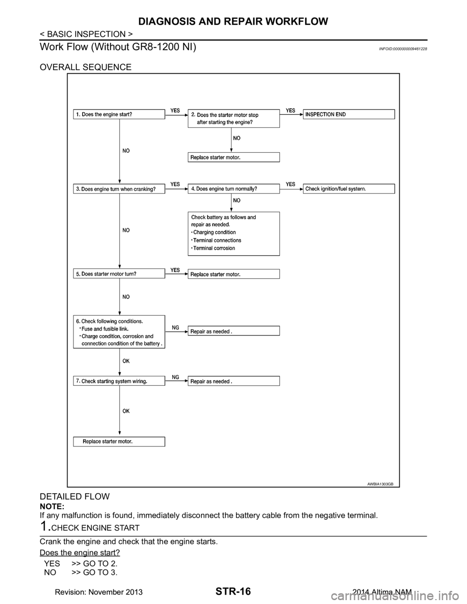
OVERALL SEQUENCE
DETAILED FLOW
NOTE:
If any malfunction is found, immediately disconnec t the battery cable from the negative terminal.
1.CHECK ENGINE START
Crank the engine and check that the engine starts.
Does the engine start?
YES >> GO TO 2.
NO >> GO TO 3.
AWBIA1303GB
Revision: November 20132014 Altima NAMRevision: November 20132014 Altima NAM
Page 4207 of 4801

DIAGNOSIS AND REPAIR WORKFLOWSTR-17
< BASIC INSPECTION >
C
D E
F
G H
I
J
K L
M A
STR
NP
O
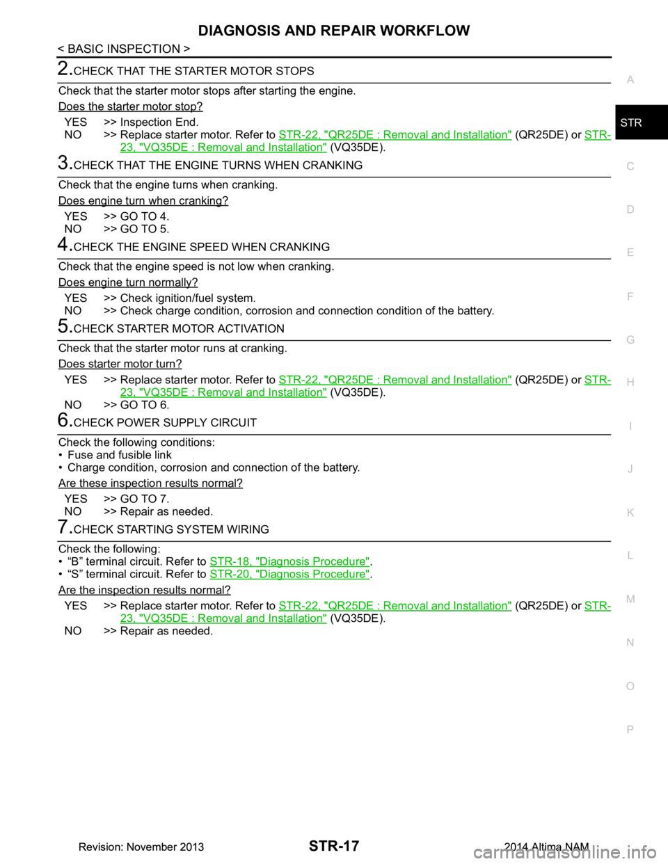
2.CHECK THAT THE STARTER MOTOR STOPS
Check that the starter motor stops after starting the engine.
Does the starter motor stop?
YES >> Inspection End.
NO >> Replace starter motor. Refer to STR-22, "QR25DE : Removal and Installation"
(QR25DE) or STR-
23, "VQ35DE : Removal and Installation" (VQ35DE).
3.CHECK THAT THE ENGINE TURNS WHEN CRANKING
Check that the engine turns when cranking.
Does engine turn when cranking?
YES >> GO TO 4.
NO >> GO TO 5.
4.CHECK THE ENGINE SPEED WHEN CRANKING
Check that the engine speed is not low when cranking.
Does engine turn normally?
YES >> Check igniti on/fuel system.
NO >> Check charge condition, corrosion and connection condition of the battery.
5.CHECK STARTER MOTOR ACTIVATION
Check that the starter motor runs at cranking.
Does starter motor turn?
YES >> Replace starter motor. Refer to STR-22, "QR25DE : Removal and Installation" (QR25DE) or STR-
23, "VQ35DE : Removal and Installation" (VQ35DE).
NO >> GO TO 6.
6.CHECK POWER SUPPLY CIRCUIT
Check the following conditions:
• Fuse and fusible link
• Charge condition, corrosion and connection of the battery.
Are these inspection results normal?
YES >> GO TO 7.
NO >> Repair as needed.
7.CHECK STARTING SYSTEM WIRING
Check the following:
• “B” terminal circuit. Refer to STR-18, "Diagnosis Procedure"
.
• “S” terminal circuit. Refer to STR-20, "Diagnosis Procedure"
.
Are the inspection results normal?
YES >> Replace starter motor. Refer to STR-22, "QR25DE : Removal and Installation" (QR25DE) or STR-
23, "VQ35DE : Removal and Installation" (VQ35DE).
NO >> Repair as needed.
Revision: November 20132014 Altima NAMRevision: November 20132014 Altima NAM
Page 4208 of 4801

STR-18
< DTC/CIRCUIT DIAGNOSIS >
B TERMINAL CIRCUIT
DTC/CIRCUIT DIAGNOSIS
B TERMINAL CIRCUIT
DescriptionINFOID:0000000009461229
Terminal “B” is constantly supplied with battery power.
Diagnosis ProcedureINFOID:0000000009461230
Regarding Wiring Diagram information, refer to STR-7, "Wiring Diagram".
CAUTION:
Perform diagnosis under the condi tion that the engine cannot start by the following procedure.
1. Remove fuel pump fuse.
2. Crank or start the engine (where possi ble) until the fuel pressure is released.
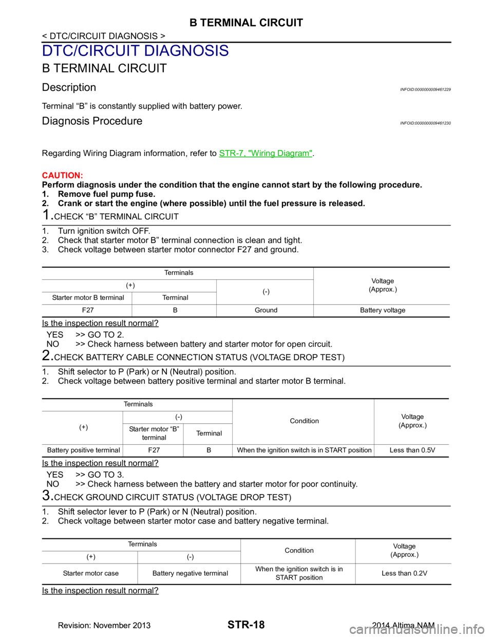
1.CHECK “B” TERMINAL CIRCUIT
1. Turn ignition switch OFF.
2. Check that starter motor B” terminal connection is clean and tight.
3. Check voltage between starter motor connector F27 and ground.
Is the inspection result normal?
YES >> GO TO 2.
NO >> Check harness between battery and starter motor for open circuit.
2.CHECK BATTERY CABLE CONNECTION STATUS (VOLTAGE DROP TEST)
1. Shift selector to P (Park) or N (Neutral) position.
2. Check voltage between battery positive terminal and starter motor B terminal.
Is the inspection result normal?
YES >> GO TO 3.
NO >> Check harness between the battery and starter motor for poor continuity.
3.CHECK GROUND CIRCUIT STATUS (VOLTAGE DROP TEST)
1. Shift selector lever to P (Park) or N (Neutral) position.
2. Check voltage between starter motor case and battery negative terminal.
Is the inspection result normal?
Te r m i n a l s
Voltage
(Approx.)
(+)
(-)
Starter motor B terminal Terminal
F27 B Ground Battery voltage
Te r m i n a l s
ConditionVoltage
(Approx.)
(+) (-)
Starter motor “B” terminal Te r m i n a l
Battery positive terminal F27 B When the ignition switch is in START position Less than 0.5V
Te r m i n a l s ConditionVoltage
(Approx.)
(+) (-)
Starter motor case Battery negative terminal When the ignition switch is in
START position Less than 0.2V
Revision: November 20132014 Altima NAMRevision: November 20132014 Altima NAM
Page 4209 of 4801

B TERMINAL CIRCUITSTR-19
< DTC/CIRCUIT DIAGNOSIS >
C
D E
F
G H
I
J
K L
M A
STR
NP
O
YES >> “B” terminal circuit is OK. Furt
her inspection is necessary. Refer to STR-12, "Work Flow (With
GR8-1200 NI)" or STR-16, "Work Flow (Without GR8-1200 NI)".
NO >> Check the starter motor case to engine mounting for high resistance.
Revision: November 20132014 Altima NAMRevision: November 20132014 Altima NAM
Page 4210 of 4801

STR-20
< DTC/CIRCUIT DIAGNOSIS >
S CONNECTOR CIRCUIT
S CONNECTOR CIRCUIT
DescriptionINFOID:0000000009461231
The starter motor magnetic switch is supplied with power when the ignition switch is turned to the START posi-
tion while the selector lever is in the P (Park) or N (Neutral) position.
Diagnosis ProcedureINFOID:0000000009461232
Regarding Wiring Diagram information, refer to STR-7, "Wiring Diagram".
CAUTION:
Perform diagnosis under the condi tion that engine cannot start by the following procedure.
1. Remove fuel pump fuse.
2. Crank or start the engine (where possi ble) until the fuel pressure is released.
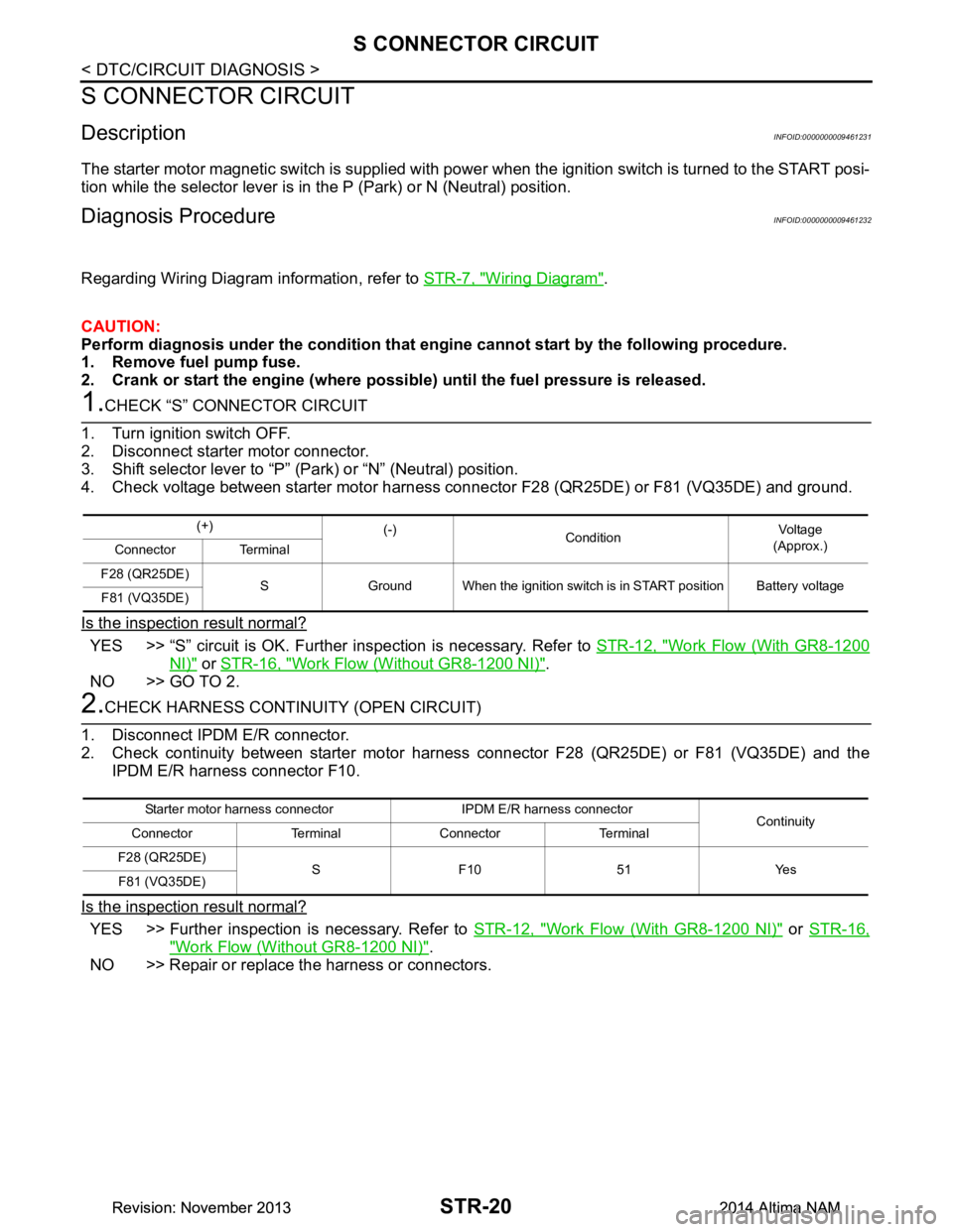
1.CHECK “S” CONNECTOR CIRCUIT
1. Turn ignition switch OFF.
2. Disconnect starter motor connector.
3. Shift selector lever to “P” (Park) or “N” (Neutral) position.
4. Check voltage between starter motor harness con nector F28 (QR25DE) or F81 (VQ35DE) and ground.
Is the inspection result normal?
YES >> “S” circuit is OK. Further inspection is necessary. Refer to STR-12, "Work Flow (With GR8-1200
NI)" or STR-16, "Work Flow (Without GR8-1200 NI)".
NO >> GO TO 2.
2.CHECK HARNESS CONTI NUITY (OPEN CIRCUIT)
1. Disconnect IPDM E/R connector.
2. Check continuity between starter motor harness connector F28 (QR25DE) or F81 (VQ35DE) and the
IPDM E/R harness connector F10.
Is the inspection result normal?
YES >> Further inspection is necessary. Refer to STR-12, "Work Flow (With GR8-1200 NI)" or STR-16,
"Work Flow (Without GR8-1200 NI)".
NO >> Repair or replace the harness or connectors.
(+) (-)
Condition Voltage
(Approx.)
Connector Terminal
F28 (QR25DE) S Ground When the ignition switch is in START position Battery voltage
F81 (VQ35DE)
Starter motor harness connector IPDM E/R harness connector Continuity
Connector Terminal Connector Terminal
F28 (QR25DE) S F10 51 Yes
F81 (VQ35DE)
Revision: November 20132014 Altima NAMRevision: November 20132014 Altima NAM
Page 4246 of 4801
![NISSAN TEANA 2014 Service Manual
SYSTEMTM-31
< SYSTEM DESCRIPTION > [CVT: RE0F10D]
C
EF
G H
I
J
K L
M A
B
TM
N
O P
• CVT detects the vehicle driving status from switc hes, sensors and signals, and controls the vehicle so that
the NISSAN TEANA 2014 Service Manual
SYSTEMTM-31
< SYSTEM DESCRIPTION > [CVT: RE0F10D]
C
EF
G H
I
J
K L
M A
B
TM
N
O P
• CVT detects the vehicle driving status from switc hes, sensors and signals, and controls the vehicle so that
the](/manual-img/5/57390/w960_57390-4245.png)
SYSTEMTM-31
< SYSTEM DESCRIPTION > [CVT: RE0F10D]
C
EF
G H
I
J
K L
M A
B
TM
N
O P
• CVT detects the vehicle driving status from switc hes, sensors and signals, and controls the vehicle so that
the optimum shift position and shift timing may always be achieved. It also controls the vehicle to reduce
shift and lockup shock, etc.
• Receives input signals from switches and sensors.
• Sends the output signal necessary for operation of so lenoid valves, and evaluates the line pressure, shift
timing, lockup operation, engine brake performance, etc.
• If a malfunction occurs on the electric system, activa te the fail-safe mode only to drive the vehicle.
LIST OF CONTROL ITEMS AND INPUT/OUTPUT
*: If these input/output signals show errors, TCM activates the fail-safe function.
CVT CONTROL SYSTEM : Fail-safeINFOID:0000000009463988
TCM has a fail-safe mode. The mode functions so that operation can be continued even if the signal circuit of
the main electronically controlled input/output parts is damaged.
If the vehicle shows following behaviors including “poor acceleration”, a malfunction of the applicable system
is detected by TCM and the vehicle may be in a fail-s afe mode. At this time, check the DTC code and perform
inspection and repair according to the malfunction diagnosis procedures.
Fail-safe function
Control Item Shift control Line pressure
control Select control Lock-up con-
trol Fail-safe func-
tion*
Input Engine torque signal
(CAN communication) ×××××
Engine speed signal
(CAN communication) ×××××
Accelerator pedal position signal
(CAN communication) ××××
Closed throttle position signal
(CAN communication) ×× ×
Stop lamp switch signal
(CAN communication) ××××
Primary pressure sensor ×
Secondary pressure sensor ×× ×
CVT fluid temperature sensor ×××××
Primary speed sensor ×××××
Output speed sensor ×× ××
Input speed sensor ×××××
Transmission range switch ×××××
Overdrive control switch
(CAN communication) ×× ×
Output Line pressure solenoid valve
××× ×
Primary pressure solenoid valve ×× ×
Torque converter clutch solenoid
valve ××
Secondary pressure solenoid valve ×× ×
Select solenoid valve ×××
Shift position indicator
(CAN communication) ×
O/D OFF indicator lamp
(CAN communication) ×
Revision: November 20132014 Altima NAMRevision: November 20132014 Altima NAM
Page 4256 of 4801
![NISSAN TEANA 2014 Service Manual
DIAGNOSIS SYSTEM (TCM)TM-41
< SYSTEM DESCRIPTION > [CVT: RE0F10D]
C
EF
G H
I
J
K L
M A
B
TM
N
O P
DIAGNOSIS SYSTEM (TCM)
DIAGNOSIS DESCRIPTION
DIAGNOSIS DESCRIPTION : 1 Tr ip Detection Diagnosis and NISSAN TEANA 2014 Service Manual
DIAGNOSIS SYSTEM (TCM)TM-41
< SYSTEM DESCRIPTION > [CVT: RE0F10D]
C
EF
G H
I
J
K L
M A
B
TM
N
O P
DIAGNOSIS SYSTEM (TCM)
DIAGNOSIS DESCRIPTION
DIAGNOSIS DESCRIPTION : 1 Tr ip Detection Diagnosis and](/manual-img/5/57390/w960_57390-4255.png)
DIAGNOSIS SYSTEM (TCM)TM-41
< SYSTEM DESCRIPTION > [CVT: RE0F10D]
C
EF
G H
I
J
K L
M A
B
TM
N
O P
DIAGNOSIS SYSTEM (TCM)
DIAGNOSIS DESCRIPTION
DIAGNOSIS DESCRIPTION : 1 Tr ip Detection Diagnosis and 2 Trip Detection Diagno-
sis
INFOID:0000000009463996
NOTE:
“Start the engine and turn OFF the ignition switch after warm-up.” This is defined as 1 trip.
1 TRIP DETECTION DIAGNOSIS
When initial malfunction is detected, TCM memorize s DTC. In these diagnoses, some illuminate MIL and
some do not. Refer to TM-60, "DTC Index"
.
2 TRIP DETECTION DIAGNOSIS
When initial malfunction is detected, TCM memorizes DTC of the 1st trip. MIL does not light at this stage. <1
trip>
If the same malfunction is detected again in next drivi ng, TCM memorizes DTC. When DTC is memorized, MIL
lights. <2 trip>
“Trip” of the “2 trip detection diagnosis” indicates the driving mode that executes self-diagnosis during driving.
×: Check possible —: Check not possible
DIAGNOSIS DESCRIPTION : DTC and DTC of 1st TripINFOID:0000000009463997
2 TRIP DETECTION DIAGNOSIS THAT ILLUMINATES MIL
• The DTC number of the 1st trip is the same as the DTC number.
• When a malfunction is detected at the 1st trip, TCM memo rizes DTC of the 1st trip. MIL does not light at this
stage. If the same malfunction is not detected at t he 2nd trip (conforming to necessary driving conditions),
DTC at the 1st trip is erased from TCM. If the same malfunction is detected at the 2nd trip, TCM memorizes
DTC and MIL lights at the same time.
• The DTC of the 1st trip is specified in Service $01 of SAE J1979/ISO 15031-5. Since detection of DTC at the
1st trip does not illuminate MIL, warning for a problem is not given to a driver.
• For procedure to delete DTC and 1st trip DTC from TCM, refer to TM-43, "CONSULT Function"
.
• If DTC of the 1st trip is detected, it is necessary to check the cause according to the “Diagnosis flow”. Refer
to TM-77, "Flowchart of Trouble Diagnosis"
.
DIAGNOSIS DESCRIPTION : Malf unction Indicator Lamp (MIL)INFOID:0000000009463998
• TCM not only detects DTC, but also sends the MI L signal to ECM through CAN communication. ECM sends
the MIL signal to the combination meter through CAN communication according to the signal, and illumi-
nates MIL.
• For malfunction indicator lamp (MIL) description, refer to EC-74, "DIAGNOSIS DESCRIPTION : Malfunction
Indicator Lamp (MIL)".
DIAGNOSIS DESCRIPTION : Counter SystemINFOID:0000000009463999
RELATION BETWEEN DTC AT 1ST TRIP/DTC/MIL AND DRIVING CONDITIONS (FOR 2 TRIP DE-
TECTION DIAGNOSIS THAT ILLUMINATES MIL)
• When initial malfunction is detected, TCM memorizes DT C of the 1st trip. MIL does not light at this stage.
• If the same malfunction is detect ed at the 2nd trip, TCM memorizes DTC and MIL lights at the same time.
• Then, MIL goes after driving the vehicle for 3 tr ips under “Driving condition B” without malfunction.
• DTC is displayed until 40 trips of “Driving condition A” are satisfied without detecting the same malfunction.
DTC is erased when 40 trips are satisfied.
Item DTC at the 1st trip DTC MIL
Display at the 1st trip Display at the
2nd trip Display at the
1st trip Display at the
2nd trip Illumination at
the 1st trip Illumination at
the 2nd trip
1 trip detection diagnosis
(Refer to TM-60, "DTC Index"
) ——
×— ×—
2 trip detection diagnosis
(Refer to TM-60, "DTC Index"
) ×
—— ×— ×
Revision: November 20132014 Altima NAMRevision: November 20132014 Altima NAM
Page 4259 of 4801
![NISSAN TEANA 2014 Service Manual
TM-44
< SYSTEM DESCRIPTION >[CVT: RE0F10D]
DIAGNOSIS SYSTEM (TCM)
SELF DIAGNOSTIC RESULTS
Display Item List
Refer to
TM-60, "DTC Index".
DTC at 1st trip and method to read DTC
• DTC (P0705, P0711 NISSAN TEANA 2014 Service Manual
TM-44
< SYSTEM DESCRIPTION >[CVT: RE0F10D]
DIAGNOSIS SYSTEM (TCM)
SELF DIAGNOSTIC RESULTS
Display Item List
Refer to
TM-60, "DTC Index".
DTC at 1st trip and method to read DTC
• DTC (P0705, P0711](/manual-img/5/57390/w960_57390-4258.png)
TM-44
< SYSTEM DESCRIPTION >[CVT: RE0F10D]
DIAGNOSIS SYSTEM (TCM)
SELF DIAGNOSTIC RESULTS
Display Item List
Refer to
TM-60, "DTC Index".
DTC at 1st trip and method to read DTC
• DTC (P0705, P0711, P0720, etc.) is specified by SAE J2012/ISO 15031-6.
• DTC and DTC at 1st trip are displayed on “Self Diagnostic results” of CONSULT.
When DTC is currently detected, “CRNT” is displayed. If “PAST” is displayed, it shows a malfunction
occurred in the past. The trip number of drive wit hout malfunction of concerned DTC can be confirmed with
“IGN counter” inside “FFD”.
• When the DTC at the 1st trip is detected, “1t” is displayed.
DTC deletion method
NOTE:
If the ignition switch is left ON after repair, turn O FF the ignition switch and wait for 10 seconds or more. Then,
turn the ignition ON again. (Engine stop)
1. Touch “TRANSMISSION” of CONSULT.
2. Touch “Self Diagnostic Result”.
3. Touch “Erase”. (DTC memorized in TCM is erased.)
IGN counter
The ignition counter is displayed in “FFD” and the number of times of satisfied “Driving condition A” is dis-
played after normal recovery of DTC. Refer to TM-41, "DIAGNOSIS DESCRIPTION : Counter System"
.
• If malfunction (DTC) is currently detected, “0” is displayed.
• After normal recovery, every time “Driving condition A” is satisfied, the display value increases from 1 → 2 →
3...38 → 39.
• When MIL turns OFF due to the malfunction and t he counter reaches 40, the DTC is erased.
NOTE:
The counter display of “40” cannot be checked.
DATA MONITOR
NOTE:
The following table includes information (items) inapplicable to this vehicle. For information (items) applicable
to this vehicle, refer to CONSULT display items.
× : Application : Optional selection
Conditions Function
Work Support The settings for ECU functions can be changed.
Self Diagnostic Results The ECU self diagnostic results are displayed.
Data Monitor The ECU input/output data is displayed in real time.
CAN Diagnosis Support Monitor The result of transmit/receive diagnosis of CAN communication is displayed.
Active Test The ECU activates outputs to test components.
ECU Identification The ECU part number is displayed.
CALIB DATA The calibration data status of TCM can be checked.
Monitored item (Unit) Monitor item selection
Remarks
ECU IN-
PUT SIG-
NALS MAIN SIG-
NALS
VSP SENSOR (km/h or mph) ×Displays the vehicle speed calculated from the CVT out-
put shaft speed.
ESTM VSP SIG (km/h or mph) ו Displays the vehi
cle speed signal (ABS) received
through CAN communication.
• Models with ABS are displayed.
INPUT SPEED SENSOR (rpm) ×Displays the input speed calculated from the pulse signal
of the input speed sensor.
PRI SPEED SEN (rpm) ×Displays the primary pulley speed calculated from the
pulse signal of the primary speed sensor.
Revision: November 20132014 Altima NAMRevision: November 20132014 Altima NAM