2014 NISSAN TEANA steering wheel
[x] Cancel search: steering wheelPage 2462 of 4801
FAX-10
< REMOVAL AND INSTALLATION >
FRONT DRIVE SHAFT
FRONT DRIVE SHAFT
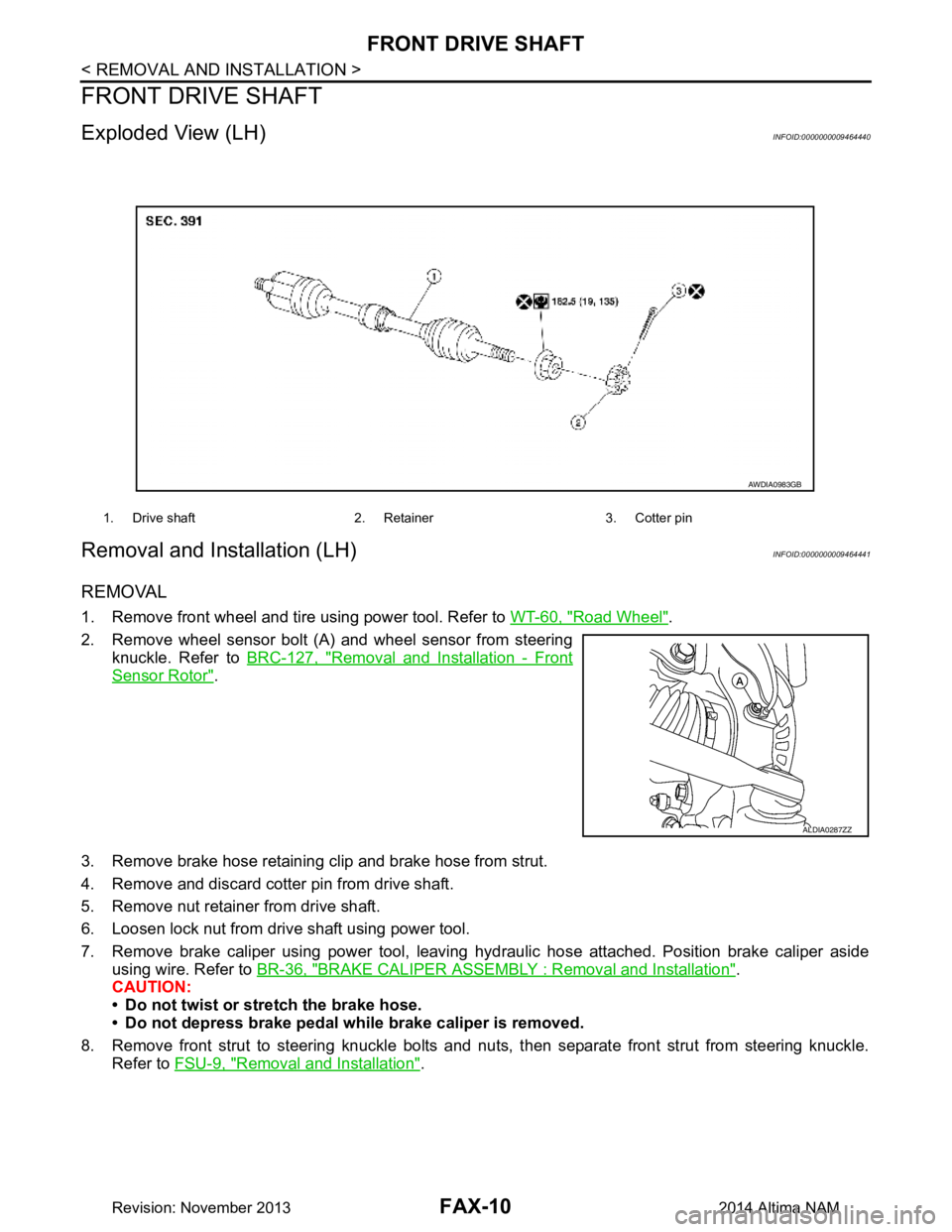
Exploded View (LH)INFOID:0000000009464440
Removal and Installation (LH)INFOID:0000000009464441
REMOVAL
1. Remove front wheel and tire using power tool. Refer to WT-60, "Road Wheel".
2. Remove wheel sensor bolt (A) and wheel sensor from steering knuckle. Refer to BRC-127, "Removal and Installation - Front
Sensor Rotor".
3. Remove brake hose retaining clip and brake hose from strut.
4. Remove and discard cotter pin from drive shaft.
5. Remove nut retainer from drive shaft.
6. Loosen lock nut from drive shaft using power tool.
7. Remove brake caliper using power tool, leaving hy draulic hose attached. Position brake caliper aside
using wire. Refer to BR-36, "BRAKE CALIPER ASSEMBLY : Removal and Installation"
.
CAUTION:
• Do not twist or stretch the brake hose.
• Do not depress brake pedal while brake caliper is removed.
8. Remove front strut to steering knuckle bolts and nut s, then separate front strut from steering knuckle.
Refer to FSU-9, "Removal and Installation"
.
1. Drive shaft 2. Retainer 3. Cotter pin
AWDIA0983GB
ALDIA0287ZZ
Revision: November 20132014 Altima NAM
Page 2464 of 4801
FAX-12
< REMOVAL AND INSTALLATION >
FRONT DRIVE SHAFT
1. Check CVT fluid level and leakage. Refer to TM-84, "Adjustment" (REOF10D), TM-286, "Adjustment"
(REOF10E).
2. Check wheel alignment. Refer to FSU-7, "Inspection and Adjustment"
.
3. Adjust the neutral position of the steering angle sensor. Refer to BRC-58, "Work Procedure"
.
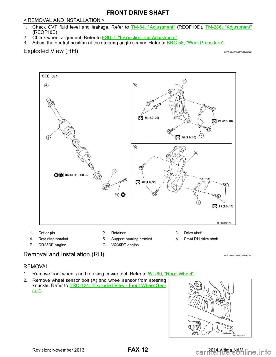
Exploded View (RH)INFOID:0000000009464442
Removal and Installation (RH)INFOID:0000000009464443
REMOVAL
1. Remove front wheel and tire using power tool. Refer to WT-60, "Road Wheel".
2. Remove wheel sensor bolt (A) and wheel sensor from steering knuckle. Refer to BRC-124, "Exploded View - Front Wheel Sen-
sor".
1. Cotter pin 2. Retainer 3. Drive shaft
4. Retaining bracket 5. Support bearing bracket A. Front RH drive shaft
B. QR25DE engine C. VQ35DE engine
ALDIA0371ZZ
ALDIA0287ZZ
Revision: November 20132014 Altima NAM
Page 2465 of 4801
FRONT DRIVE SHAFTFAX-13
< REMOVAL AND INSTALLATION >
CEF
G H
I
J
K L
M A
B
FA X
N
O P
3. Remove brake hose retaining clip and brake hose from strut.
4. Remove and discard cotter pin from drive shaft.
5. Remove nut retainer from drive shaft.
6. Loosen lock nut from drive shaft using power tool.
7. Remove brake caliper using power tool, leaving hy draulic brake hose attached. Position caliper aside
using wire. Refer to BR-36, "BRAKE CALIPER ASSEMBLY : Removal and Installation"
.
CAUTION:
• Do not twist or stretch the brake hose.
• Do not depress brake pedal while brake caliper is removed.
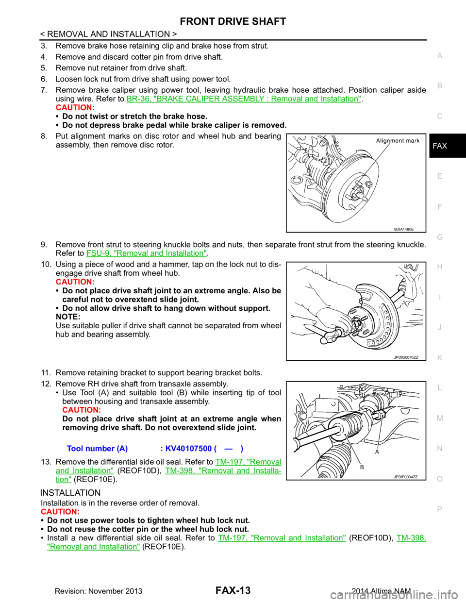
8. Put alignment marks on disc rotor and wheel hub and bearing assembly, then remove disc rotor.
9. Remove front strut to steering knuckle bolts and nuts, then separate front strut from the steering knuckle.
Refer to FSU-9, "Removal and Installation"
.
10. Using a piece of wood and a hammer, tap on the lock nut to dis- engage drive shaft from wheel hub.
CAUTION:
• Do not place drive shaft joint to an extreme angle. Also be careful not to over extend slide joint.
• Do not allow drive shaft to hang down without support.
NOTE:
Use suitable puller if drive shaft cannot be separated from wheel
hub and bearing assembly.
11. Remove retaining bracket to support bearing bracket bolts.
12. Remove RH drive shaft from transaxle assembly. • Use Tool (A) and suitable tool (B) while inserting tip of tool
between housing and transaxle assembly.
CAUTION:
Do not place drive shaft join t at an extreme angle when
removing drive shaft. Do not overextend slide joint.
13. Remove the differential side oil seal. Refer to TM-197, "Removal
and Installation" (REOF10D), TM-398, "Removal and Installa-
tion" (REOF10E).
INSTALLATION
Installation is in the reverse order of removal.
CAUTION:
• Do not use power tools to tighten wheel hub lock nut.
• Do not reuse the cotter pin or the wheel hub lock nut.
• Install a new differential side oil seal. Refer to TM-197, "Removal and Installation"
(REOF10D), TM-398,
"Removal and Installation" (REOF10E).
SDIA1480E
JPDIG0070ZZ
Tool number (A) : KV40107500 ( — )
JPDIF0004ZZ
Revision: November 20132014 Altima NAM
Page 2466 of 4801
FAX-14
< REMOVAL AND INSTALLATION >
FRONT DRIVE SHAFT
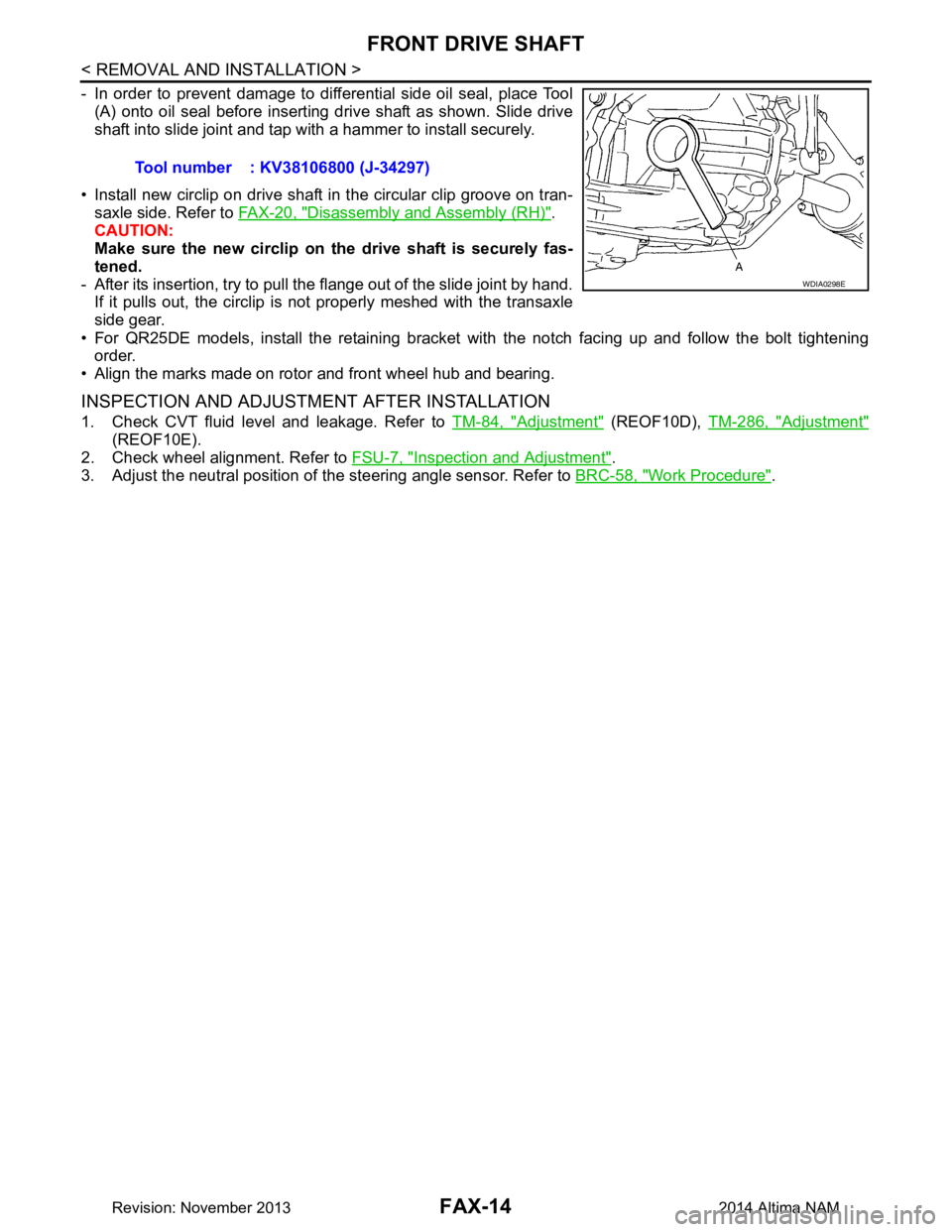
- In order to prevent damage to differential side oil seal, place Tool(A) onto oil seal before inserting drive shaft as shown. Slide drive
shaft into slide joint and tap with a hammer to install securely.
• Install new circlip on drive shaft in the circular clip groove on tran- saxle side. Refer to FAX-20, "Disassembly and Assembly (RH)"
.
CAUTION:
Make sure the new circlip on the drive shaft is securely fas-
tened.
- After its insertion, try to pull the flange out of the slide joint by hand. If it pulls out, the circlip is not properly meshed with the transaxle
side gear.
• For QR25DE models, install the retaining bracket with the notch facing up and follow the bolt tightening
order.
• Align the marks made on rotor and front wheel hub and bearing.
INSPECTION AND ADJUSTMENT AFTER INSTALLATION
1. Check CVT fluid level and leakage. Refer to TM-84, "Adjustment" (REOF10D), TM-286, "Adjustment"
(REOF10E).
2. Check wheel alignment. Refer to FSU-7, "Inspection and Adjustment"
.
3. Adjust the neutral position of the steering angle sensor. Refer to BRC-58, "Work Procedure"
.
Tool number : KV38106800 (J-34297)
WDIA0298E
Revision: November 20132014 Altima NAM
Page 2502 of 4801
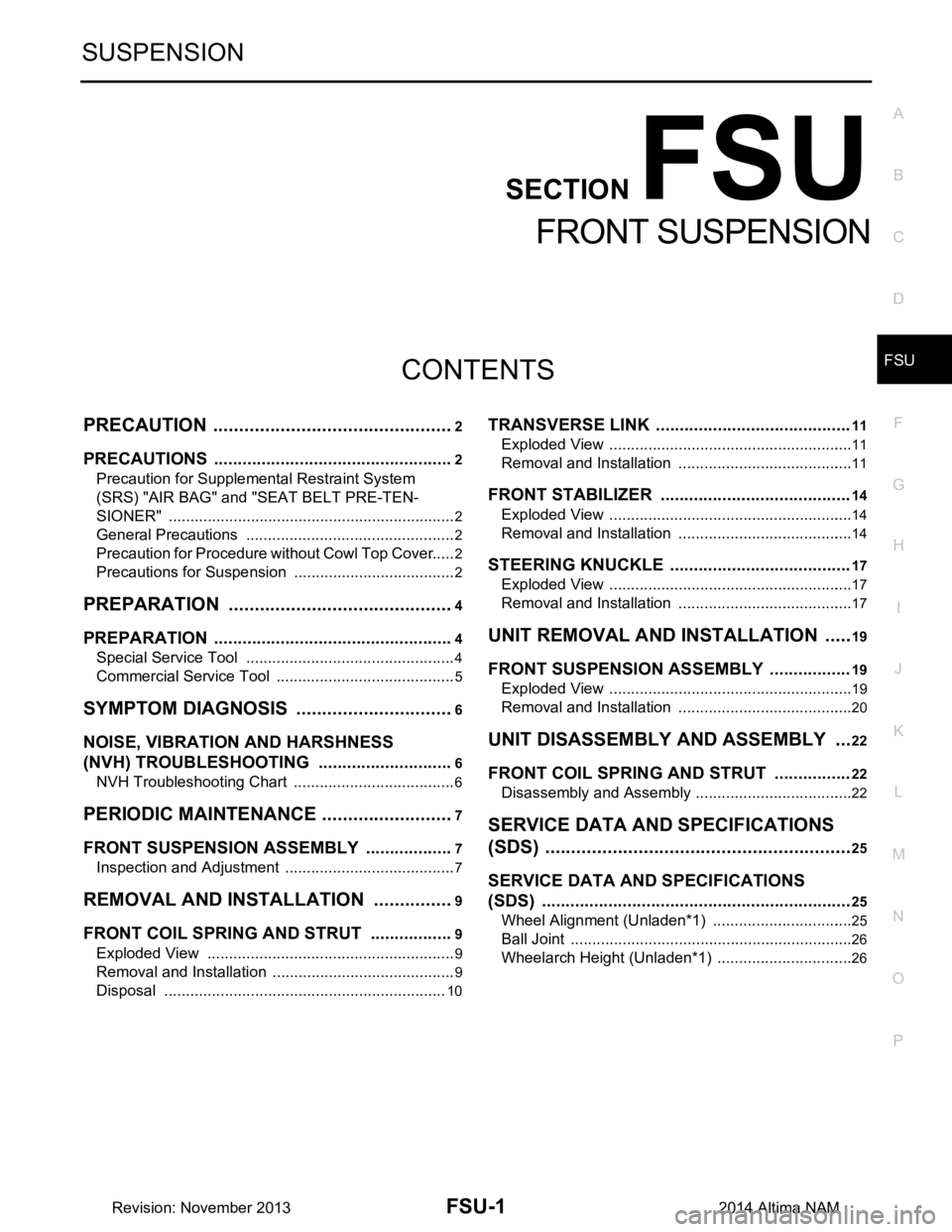
FSU-1
SUSPENSION
C
D
F
G H
I
J
K L
M
SECTION FSU
A
B
FSU
N
O PCONTENTS
FRONT SUSPENSION
PRECAUTION ................ ...............................2
PRECAUTIONS .............................................. .....2
Precaution for Supplemental Restraint System
(SRS) "AIR BAG" and "SEAT BELT PRE-TEN-
SIONER" ............................................................. ......
2
General Precautions .................................................2
Precaution for Procedure without Cowl Top Cover ......2
Precautions for Suspension ......................................2
PREPARATION ............................................4
PREPARATION .............................................. .....4
Special Service Tool ........................................... ......4
Commercial Service Tool ..........................................5
SYMPTOM DIAGNOSIS ...............................6
NOISE, VIBRATION AND HARSHNESS
(NVH) TROUBLESHOOTING ........................ .....
6
NVH Troubleshooting Chart ................................ ......6
PERIODIC MAINTENANCE ..........................7
FRONT SUSPENSION ASSEMBLY .............. .....7
Inspection and Adjustment .................................. ......7
REMOVAL AND INSTALLATION ................9
FRONT COIL SPRING AND STRUT ............. .....9
Exploded View .................................................... ......9
Removal and Installation ...........................................9
Disposal .............................................................. ....10
TRANSVERSE LINK .........................................11
Exploded View ..................................................... ....11
Removal and Installation .........................................11
FRONT STABILIZER ........................................14
Exploded View .........................................................14
Removal and Installation .........................................14
STEERING KNUCKLE ......................................17
Exploded View .........................................................17
Removal and Installation .........................................17
UNIT REMOVAL AND INSTALLATION ......19
FRONT SUSPENSION ASSEMBLY .................19
Exploded View ..................................................... ....19
Removal and Installation .........................................20
UNIT DISASSEMBLY AND ASSEMBLY ....22
FRONT COIL SPRING AND STRUT ................22
Disassembly and Assembly ................................. ....22
SERVICE DATA AND SPECIFICATIONS
(SDS) ............... .............................................
25
SERVICE DATA AND SPECIFICATIONS
(SDS) .................................................................
25
Wheel Alignment (Unladen*1) ............................. ....25
Ball Joint ..................................................................26
Wheelarch Height (Unladen*1) ................................26
Revision: November 20132014 Altima NAM
Page 2505 of 4801
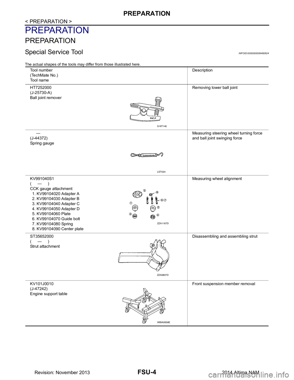
FSU-4
< PREPARATION >
PREPARATION
PREPARATION
PREPARATION
Special Service ToolINFOID:0000000009460624
The actual shapes of the tools may differ from those illustrated here.
Tool number
(TechMate No.)
Tool name Description
HT7252000
(J-25730-A)
Ball joint remover Removing lower ball joint
—
(J-44372)
Spring gauge Measuring steering wheel turning force
and ball joint swinging force
KV991040S1
(—)
CCK gauge attachment 1. KV99104020 Adapter A
2. KV99104030 Adapter B
3. KV99104040 Adapter C
4. KV99104050 Adapter D
5. KV99104060 Plate
6. KV99104070 Guide bolt
7. KV99104080 Spring
8. KV99104090 Center plate Measuring wheel alignment
ST35652000
(—)
Strut attachment Disassembling and assembling strut
KV101J0010
(J-47242)
Engine support table Front suspension member removal
S-NT146
LST024
ZZA1167D
ZZA0807D
WBIA0658E
Revision: November 20132014 Altima NAM
Page 2507 of 4801
FSU-6
< SYMPTOM DIAGNOSIS >
NOISE, VIBRATION AND HARSHNESS (NVH) TROUBLESHOOTING
SYMPTOM DIAGNOSIS
NOISE, VIBRATION AND HARSHNESS (NVH) TROUBLESHOOTING
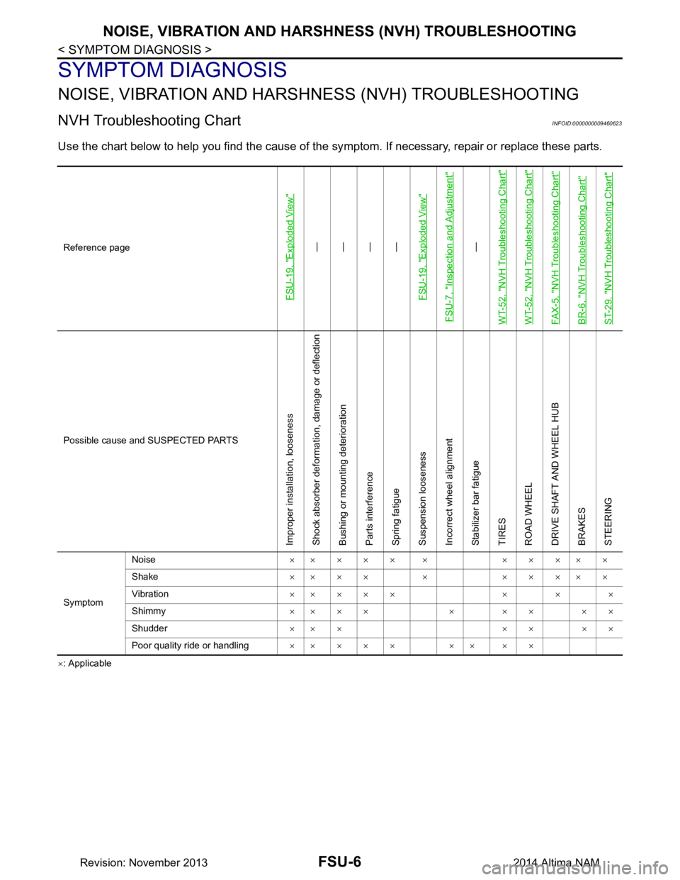
NVH Troubleshooting ChartINFOID:0000000009460623
Use the chart below to help you find the cause of the sy mptom. If necessary, repair or replace these parts.
×: ApplicableReference page
FSU-19, "Exploded View"
—
—
—
—
FSU-19, "Exploded View"
FSU-7, "Inspection and Adjustment"
—
WT-52, "NVH Troubleshooting Chart"
WT-52, "NVH Troubleshooting Chart"FAX-5, "NVH Troubleshooting Chart"BR-6, "NVH Troubleshooting Chart"ST-29, "NVH Troubleshooting Chart"
Possible cause and SUSPECTED PARTS
Improper installation, looseness Shock absorber deformation, damage or deflection
Bushing or mounting deterioration
Parts interference
Spring fatigue
Suspension looseness
Incorrect wheel alignment
Stabilizer bar fatigue
TIRES
ROAD WHEEL
DRIVE SHAFT AND WHEEL HUB
BRAKES
STEERING
Symptom Noise
××××× × ×××××
Shake ×××× × ×××××
Vibration ×× × × × × × ×
Shimmy ×× × × × × × × ×
Shudder ×× × × × × ×
Poor quality ride or handling ×× × × × ×× × ×
Revision: November 20132014 Altima NAM
Page 2508 of 4801
FRONT SUSPENSION ASSEMBLYFSU-7
< PERIODIC MAINTENANCE >
C
D
F
G H
I
J
K L
M A
B
FSU
N
O P
PERIODIC MAINTENANCE
FRONT SUSPENSION ASSEMBLY
Inspection and AdjustmentINFOID:0000000009460626
INSPECTION
Make sure the mounting conditions (looseness, back lash) of each component and component conditions
(wear, damage) are normal.
LOWER BALL JOINT END PLAY
1. Set front wheels in a straight-ahead position. Do not depress brake pedal.
2. Place an iron bar or similar tool between upper link and steering knuckle.
3. Measure axial end play by prying it up and down.Refer to FSU-26, "Ball Joint"
.
CAUTION:
Be careful not to damage ball joint boot. Do not damage the installation position by applying
excessive force.
SHOCK ABSORBER
Check for oil leakage, damage and repl ace if malfunction is detected.
WHEEL ALIGNMENT
Description
Measure wheel alignment under unladen conditions.
NOTE:
"Unladen conditions" means that fuel, engine coolant, and lubricant are full. Spare tire, jack, hand tools and
mats are in designated positions.
General Information and Recommendations
• A four-wheel thrust alignment should be performed.
- This type of alignment is re commended for any NISSAN vehicle.
- The four-wheel "thrust" process helps ensure that t he vehicle is properly aligned and the steering wheel is
centered.
- The alignment rack itself should be capable of accepting any NISSAN vehicle.
- The rack should be checked to ensure that it is level.
• Make sure the machine is properly calibrated.
- Your alignment equipment should be regularly ca librated in order to give correct information.
- Check with the manufacturer of your specific equi pment for their recommended Service/Calibration Sched-
ule.
Preliminary Check
Check the following:
1. Tires for improper air pressure and wear.
2. Road wheels for runout. Refer to WT-60, "Road Wheel"
.
3. Wheel bearing axial end play. Refer to FAX-27, "Wheel Bearing"
.
4. Transverse link ball joint axial end play. Refer to FSU-11, "Removal and Installation"
.
5. Shock absorber operation.
6. Each mounting part of axle and suspension for looseness and deformation.
7. Each of suspension member, shock absorber, upper link and transverse link for cracks, deformation and other damage.
8. Vehicle height (posture).
Alignment Process
IMPORTANT:
Use only the alignment specificati ons listed in this Service Manual.
• When displaying the alignment settings, m any alignment machines use "indicators" Do not use these indi-
cators. : (Green/red, plus or minus, Go/No Go).
- The alignment specifications programmed into your machine that operate these indicators may not be cor-
rect.
Revision: November 20132014 Altima NAM