2014 NISSAN TEANA steering wheel
[x] Cancel search: steering wheelPage 2527 of 4801

FSU-26
< SERVICE DATA AND SPECIFICATIONS (SDS)
SERVICE DATA AND SPECIFICATIONS (SDS)
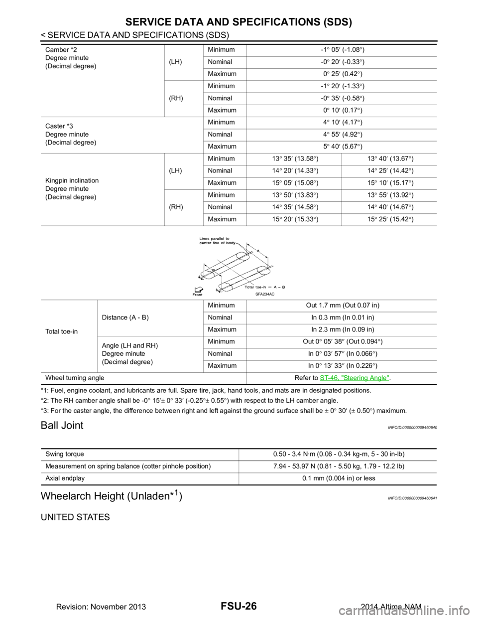
*1: Fuel, engine coolant, and lubricants are full. Spare tire, jack, hand tools, and mats are in designated positions.
*2: The RH camber angle shall be -0 ° 15 ′± 0 ° 33 ′ (-0.25 °± 0.55 °) with respect to the LH camber angle.
*3: For the caster angle, the difference between right and left against the ground surface shall be ± 0 ° 30 ′ ( ± 0.50 °) maximum.
Ball JointINFOID:0000000009460640
Wheelarch Height (Unladen*1)INFOID:0000000009460641
UNITED STATES
Camber *2
Degree minute
(Decimal degree) (LH)Minimum -1
° 05 ′ (-1.08 °)
Nominal -0 ° 20 ′ (-0.33 °)
Maximum 0 ° 25 ′ (0.42 °)
(RH) Minimum -1
° 20 ′ (-1.33 °)
Nominal -0 ° 35 ′ (-0.58 °)
Maximum 0 ° 10 ′ (0.17 °)
Caster *3
Degree minute
(Decimal degree) Minimum 4
° 10 ′ (4.17 °)
Nominal 4 ° 55 ′ (4.92 °)
Maximum 5 ° 40 ′ (5.67 °)
Kingpin inclination
Degree minute
(Decimal degree) (LH)
Minimum 13
° 35 ′ (13.58 °)13 ° 40 ′ (13.67 °)
Nominal 14 ° 20 ′ (14.33 °)14 ° 25 ′ (14.42 °)
Maximum 15 ° 05 ′ (15.08 °)15 ° 10 ′ (15.17 °)
(RH) Minimum 13
° 50 ′ (13.83 °)13 ° 55 ′ (13.92 °)
Nominal 14 ° 35 ′ (14.58 °)14 ° 40 ′ (14.67 °)
Maximum 15 ° 20 ′ (15.33 °)15 ° 25 ′ (15.42 °)
Total toe-in Distance (A - B)
Minimum Out 1.7 mm (Out 0.07 in)
Nominal In 0.3 mm (In 0.01 in)
Maximum In 2.3 mm (In 0.09 in)
Angle (LH and RH)
Degree minute
(Decimal degree) Minimum Out 0
° 05 ′ 38 ″ (Out 0.094 °)
Nominal In 0 ° 03 ′ 57 ″ (In 0.066 °)
Maximum In 0 ° 13 ′ 33 ″ (In 0.226 °)
Wheel turning angle Refer to ST-46, "Steering Angle"
.
SFA234AC
Swing torque 0.50 - 3.4 N·m (0 .06 - 0.34 kg-m, 5 - 30 in-lb)
Measurement on spring balance (cotter pinhole position) 7.94 - 53.97 N (0.81 - 5.50 kg, 1.79 - 12.2 lb)
Axial endplay 0.1 mm (0.004 in) or less
Revision: November 20132014 Altima NAM
Page 2564 of 4801

GI-36
< PRECAUTION >
TOW TRUCK TOWING
TOW TRUCK TOWING
Tow Truck TowingINFOID:0000000009463008
CAUTION:
• Never tow a CVT model with the rear wheels raised and the front wheels on the ground. This may
cause serious and expensive damage to the transaxle. If it is necessary to tow the vehicle with the
rear wheels raised, always use towi ng dollies under the front wheels.
• Never tow a CVT model from the rear (that is backw ard) with four wheels on the ground. This may
cause serious and expensive damage to the transaxle.
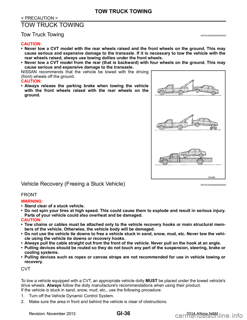
NISSAN recommends that the vehicle be towed with the driving
(front) wheels off the ground.
CAUTION:
• Always release the parking brake when towing the vehicle with the front wheels raised with the rear wheels on the
ground.
Vehicle Recovery (Freeing a Stuck Vehicle)INFOID:0000000009463009
FRONT
WARNING:
• Stand clear of a stuck vehicle.
• Do not spin your tires at high speed. This could cause them to explode and result in serious injury.
Parts of your vehicle could also overheat and be damaged.
CAUTION:
• Tow chains or cables must be attached only to the vehicle recovery hooks or main structural mem-
bers of the vehicle. Otherwise, the vehicle body will be damaged.
• Do not use the vehicle tie downs to free a vehicle stuck in sand, snow, mud, etc. Never tow the vehi-
cle using the vehicle tie downs or recovery hooks.
• Always pull the cable straight out from the front of the vehicle. Never pull on the hook at an angle.
• Pulling devices should be routed so they do not touch any part of the suspension, steering, brake or
cooling systems.
• Pulling devices such as ropes or canvas straps ar e not recommended for use in vehicle towing or
recovery.
CVT
To tow a vehicle equipped with a CVT, an appropriate vehicle dolly MUST be placed under the towed vehicle's
drive wheels. Always follow the dolly manufacture's recommendations when using their product.
If the vehicle is stuck in sand, snow , mud, etc., use the following procedure:
1. Turn off the Vehicle Dynamic Control System.
2. Make sure the area in front and behind the vehicle is clear of obstructions.
SGI986
Revision: November 20132014 Altima NAMRevision: November 20132014 Altima NAM
Page 2565 of 4801

TOW TRUCK TOWINGGI-37
< PRECAUTION >
C
D E
F
G H
I
J
K L
M B
GI
N
O P
3. Turn the steering wheel right and left to clear an area around the front tires.
4. Slowly rock the vehicle forward and backward. Shift back and forth between R (reverse) and D (drive).
Apply the accelerator as little as possible to maintain the rocking motion.
Release the accelerator pedal before shifting between R and D.
Do not spin the tires above 35 m.p.h. (55 km/h).
5. If the vehicle can not be freed after a few tries, cont act a professional towing service to remove the vehi-
cle.
Revision: November 20132014 Altima NAMRevision: November 20132014 Altima NAM
Page 2678 of 4801
![NISSAN TEANA 2014 Service Manual
A/C AUTO AMP.HAC-29
< ECU DIAGNOSIS INFORMATION > [AUTOMATIC AIR CONDITIONER]
C
D E
F
G H
J
K L
M A
B
HAC
N
O P
Te r m i n a l N o . (Wire color) Description
ConditionVa l u e
(Approx.)
+ − Sign NISSAN TEANA 2014 Service Manual
A/C AUTO AMP.HAC-29
< ECU DIAGNOSIS INFORMATION > [AUTOMATIC AIR CONDITIONER]
C
D E
F
G H
J
K L
M A
B
HAC
N
O P
Te r m i n a l N o . (Wire color) Description
ConditionVa l u e
(Approx.)
+ − Sign](/manual-img/5/57390/w960_57390-2677.png)
A/C AUTO AMP.HAC-29
< ECU DIAGNOSIS INFORMATION > [AUTOMATIC AIR CONDITIONER]
C
D E
F
G H
J
K L
M A
B
HAC
N
O P
Te r m i n a l N o . (Wire color) Description
ConditionVa l u e
(Approx.)
+ − Signal name Input/
Output
1
(L) —CAN-H Input/
Output ——
2
(B) —Ground — — —
3
(SB) Ground Battery power supply Input Ignition switch OFF Battery voltage
4
(BR) Ground TX FR Output Ignition switch ON 0 – 5 V
7
(L) Ground Ambient sensor signal Input Ignition switch ON 0 – 4.8 V
Output voltage varies with ambi- ent temperature
8
*1
(BR) Ground
Heated steering wheel
switch signal InputIgnition
switch ON Heated steer-
ing wheel
switch: While
pressing 0 V
Other than the
above 12 V
9
(G) Ground Sunload sensor signal Input Ignition switch ON 0 – 4.8 V
Output voltage varies with sun- load amount
13
(P) Ground IGN 2 Input Ignition switch ON Battery voltage
15
(Y) Ground RR DEF switch Output Defroster
switch OFF 0 V
ON 12 V
16
(G) Ground Each door motor LIN signal
Input/
Output Ignition switch ON
17
(W) GroundEach door motor power
supply Output Ignition switch ON 12 V
18
(P) Ground
Front blower motor control
signal Output• Ignition switch ON
• Front fan speed: 1st
speed (manual)
20
*1
(P) Ground
Heated steering wheel relay
control signal OutputIgnition
switch ON Within 30 sec-
onds after
turning ON
the heated
steering
switch. 0 V
Other than the
above 12 V
21
(P) —CAN-L Input/
Output ——
SJIA1453J
JSIIA0096ZZ
Revision: November 20132014 Altima NAMRevision: November 20132014 Altima NAM
Page 2679 of 4801
![NISSAN TEANA 2014 Service Manual
HAC-30
< ECU DIAGNOSIS INFORMATION >[AUTOMATIC AIR CONDITIONER]
A/C AUTO AMP.
*1: With heated steering wheel
DTC Inspection Priority ChartINFOID:0000000009463105
If some DTCs are displayed at the sam NISSAN TEANA 2014 Service Manual
HAC-30
< ECU DIAGNOSIS INFORMATION >[AUTOMATIC AIR CONDITIONER]
A/C AUTO AMP.
*1: With heated steering wheel
DTC Inspection Priority ChartINFOID:0000000009463105
If some DTCs are displayed at the sam](/manual-img/5/57390/w960_57390-2678.png)
HAC-30
< ECU DIAGNOSIS INFORMATION >[AUTOMATIC AIR CONDITIONER]
A/C AUTO AMP.
*1: With heated steering wheel
DTC Inspection Priority ChartINFOID:0000000009463105
If some DTCs are displayed at the same time, perfo
rm inspections one by one based on the following priority
chart.
22
(B) —Ground — — —
23
(G) Ground Ignition power supply Input Ignition switch ON Battery voltage
24
(V) Ground RX FR Input Ignition switch ON 0 – 5 V
26
(W) — Sensor ground — — —
27
(G) Ground In-vehicle sensor signal Input Ignition switch ON 0 – 4.8 V
Output voltage varies with in-vehi-
cle temperature
28
(P) Ground Intake sensor signal Input Ignition switch ON 0 – 4.8 V
Output voltage varies with front evaporator fin temperature
35
(P) Ground RR DEF feedback Input
Defroster
switch OFF 0 V
ON 12 V
37
(B) — ACTR Ground — — —
40
(G) Ground
ECV (electrical control
valve) control signal Output• Ignition switch ON
• Active test (HVAC test):
MODE 1
Te r m i n a l N o .
(Wire color) Description
ConditionVa l u e
(Approx.)
+ − Signal name Input/
Output
SJIA1607E
Revision: November 20132014 Altima NAMRevision: November 20132014 Altima NAM
Page 2941 of 4801

INSTRUMENT PANEL ASSEMBLYIP-15
< REMOVAL AND INSTALLATION >
C
D E
F
G H
I
K L
M A
B
IP
N
O P
Removal and Installation INFOID:0000000009461379
CAUTION:
• Be careful not to scratch instrument panel pad and other parts.
• Whenever a suitable tool is used, always wrap a cloth around the end of the tool to protect compo-
nents from damage.
• Before servicing, turn ignition swit ch OFF, disconnect both battery terminals and wait at least three
minutes.
REMOVAL
1. Disconnect the negative and positive bat tery terminals, then wait at least three minutes. Refer to PG-73,
"Removal and Installation (Battery)"
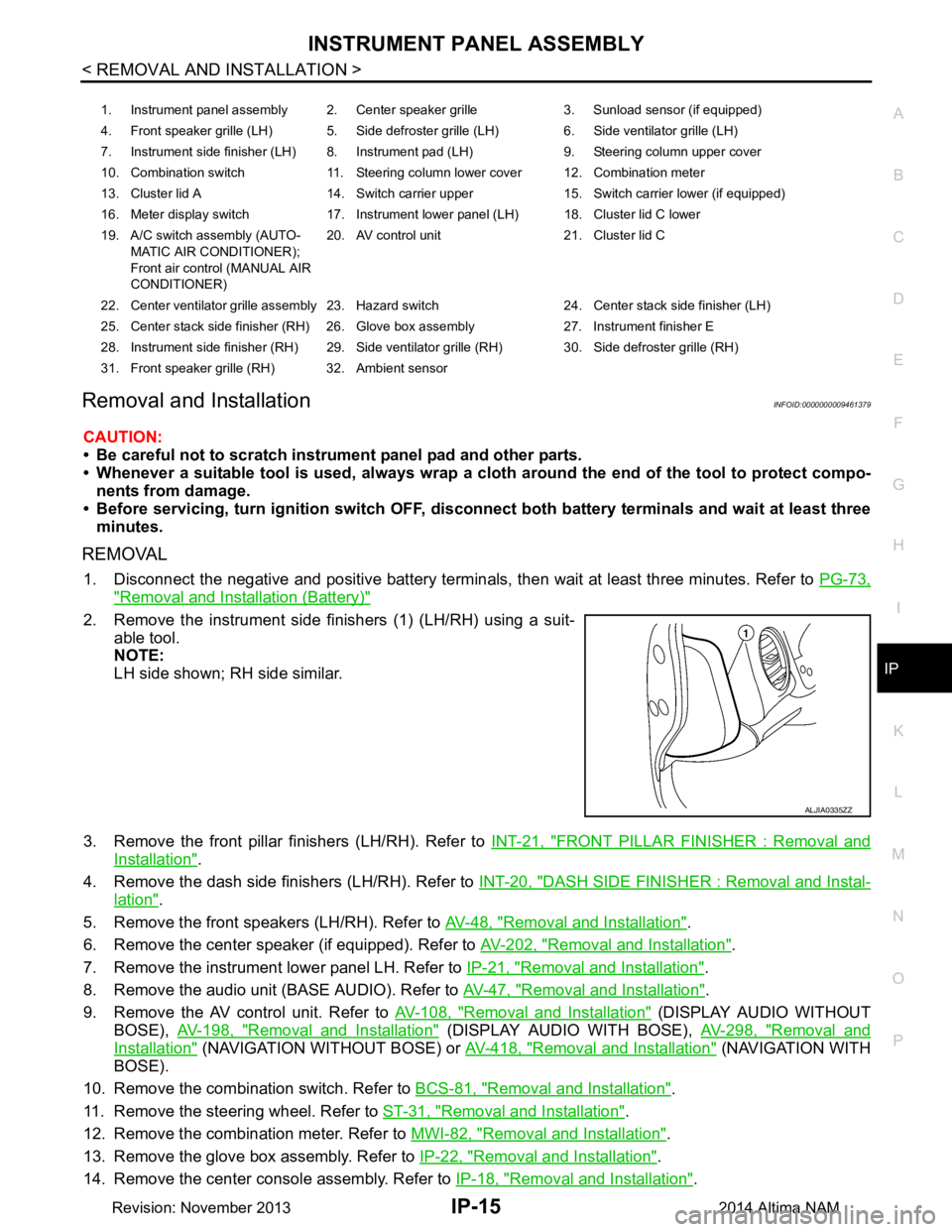
2. Remove the instrument side finishers (1) (LH/RH) using a suit-
able tool.
NOTE:
LH side shown; RH side similar.
3. Remove the front pillar finishers (LH/RH). Refer to INT-21, "FRONT PILLAR FINISHER : Removal and
Installation".
4. Remove the dash side finishers (LH/RH). Refer to INT-20, "DASH SIDE FINISHER : Removal and Instal-
lation".
5. Remove the front speakers (LH/RH). Refer to AV-48, "Removal and Installation"
.
6. Remove the center speaker (if equipped). Refer to AV-202, "Removal and Installation"
.
7. Remove the instrument lower panel LH. Refer to IP-21, "Removal and Installation"
.
8. Remove the audio unit (BASE AUDIO). Refer to AV-47, "Removal and Installation"
.
9. Remove the AV control unit. Refer to AV-108, "Removal and Installation"
(DISPLAY AUDIO WITHOUT
BOSE), AV-198, "Removal and Installation"
(DISPLAY AUDIO WITH BOSE), AV-298, "Removal and
Installation" (NAVIGATION WITHOUT BOSE) or AV-418, "Removal and Installation" ( N AV I G AT I O N W I T H
BOSE).
10. Remove the combination switch. Refer to BCS-81, "Removal and Installation"
.
11. Remove the steering wheel. Refer to ST-31, "Removal and Installation"
.
12. Remove the combination meter. Refer to MWI-82, "Removal and Installation"
.
13. Remove the glove box assembly. Refer to IP-22, "Removal and Installation"
.
14. Remove the center console assembly. Refer to IP-18, "Removal and Installation"
.
1. Instrument panel assembly 2. Center speaker grille 3. Sunload sensor (if equipped)
4. Front speaker grille (LH) 5. Side defroster grille (LH) 6. Side ventilator grille (LH)
7. Instrument side finisher (LH) 8. Instrument pad (LH) 9. Steering column upper cover
10. Combination switch 11. Steering column lower cover 12. Combination meter
13. Cluster lid A 14. Switch carrier upper 15. Switch carrier lower (if equipped)
16. Meter display switch 17. Instrument lower panel (LH) 18. Cluster lid C lower
19. A/C switch assembly (AUTO- MATIC AIR CONDITIONER);
Front air control (MANUAL AIR
CONDITIONER) 20. AV control unit 21. Cluster lid C
22. Center ventilator grille assembly 23. Hazard switch 24. Center stack side finisher (LH)
25. Center stack side finisher (RH) 26. Glove box assembly 27. Instrument finisher E
28. Instrument side finisher (RH) 29. Side ventilator grille (RH) 30. Side defroster grille (RH)
31. Front speaker grille (RH) 32. Ambient sensor
ALJIA0335ZZ
Revision: November 20132014 Altima NAM
Page 2943 of 4801

STEERING COLUMN COVERSIP-17
< REMOVAL AND INSTALLATION >
C
D E
F
G H
I
K L
M A
B
IP
N
O P
STEERING COLUMN COVERS
Removal and InstallationINFOID:0000000009461380
REMOVAL
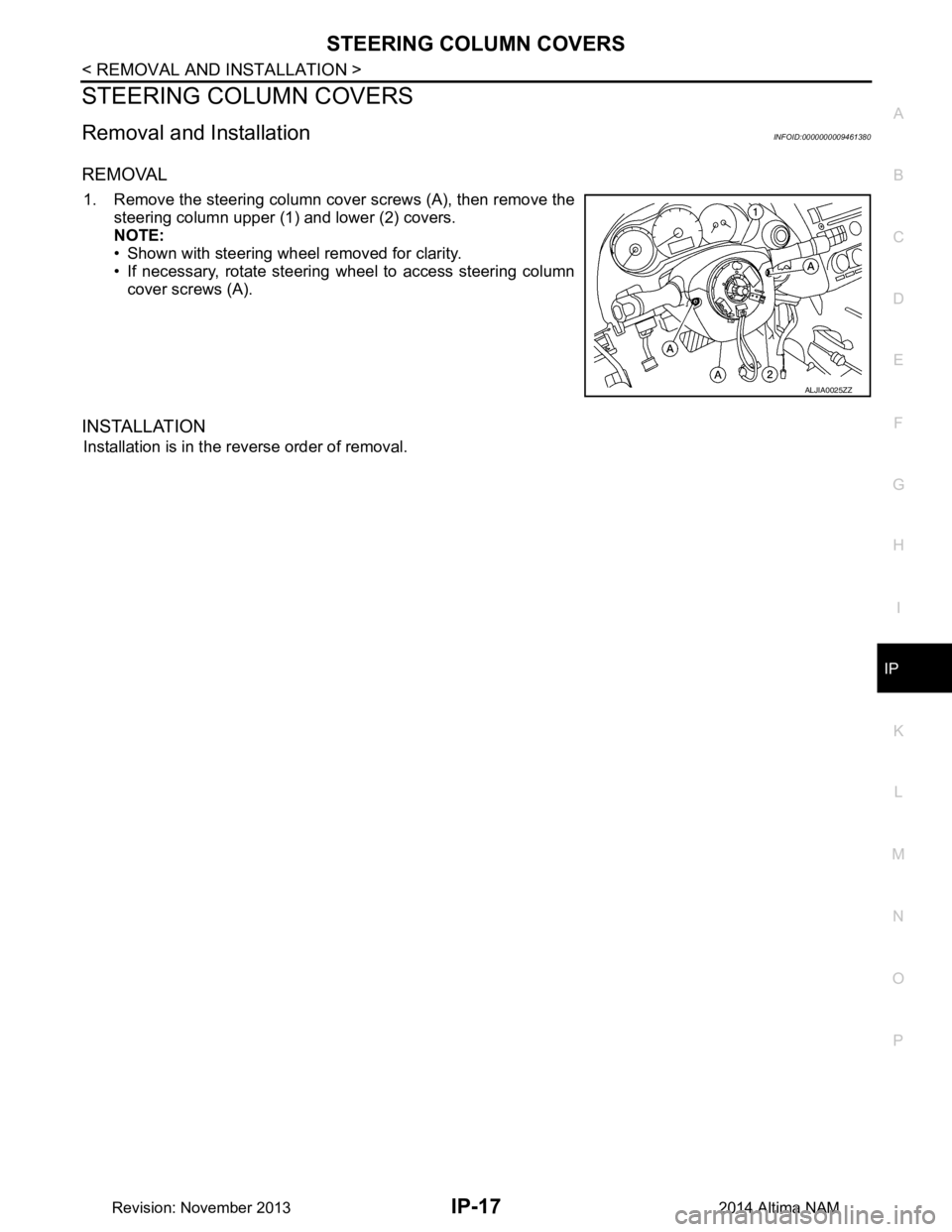
1. Remove the steering column cover screws (A), then remove the steering column upper (1) and lower (2) covers.
NOTE:
• Shown with steering wheel removed for clarity.
• If necessary, rotate steering wheel to access steering column
cover screws (A).
INSTALLATION
Installation is in the reverse order of removal.
ALJIA0025ZZ
Revision: November 20132014 Altima NAM
Page 3186 of 4801

MA-2
OIL FILTER : Removal and Installation ..................27
SPARK PLUG ........................................................ ...28
SPARK PLUG : Removal and Installation ..............29
EVAP VAPOR LINES ............................................. ...30
EVAP VAPOR LINES : Inspection ..........................30
CHASSIS AND BODY MAINTENANCE ......... ...31
IN-CABIN MICROFILTER ...................................... ...31
IN-CABIN MICROFILTER : Removal and Installa-
tion ....................................................................... ...
31
EXHAUST SYSTEM ............................................... ...31
EXHAUST SYSTEM : Checking Exhaust System ...31
CVT FLUID ............................................................. ...31
CVT FLUID : RE0F10D ..........................................32
CVT FLUID : Inspection ..........................................32
CVT FLUID : Replacement .....................................32
CVT FLUID : Adjustment ........................................34
CVT FLUID : RE0F10E ..........................................35
CVT FLUID : Inspection ..........................................35
CVT FLUID : Replacement .....................................35
CVT FLUID : Adjustment ........................................37
WHEELS ................................................................ ...38
WHEELS : Inspection .............................................38
WHEELS : Adjustment ...........................................39
BRAKE FLUID LEVEL AND LEAKS ........................40
BRAKE FLUID LEVEL AND LEAKS : Inspection ...40
BRAKE LINES AND CABLES ............................... ...41
BRAKE LINES AND CABLES : Inspection .............41
BRAKE FLUID ........................................................ ...41
BRAKE FLUID : Drain and Refill .............................41
DISC BRAKE .......................................................... ...42
DISC BRAKE : Front Brake Pad .............................42
DISC BRAKE : Inspection .......................................42
DISC BRAKE : Front Brake Rotor ...........................42
DISC BRAKE : Inspection .......................................42
DISC BRAKE : Rear Brake Pad ..............................43
DISC BRAKE : Inspection .......................................43
DISC BRAKE : Rear Brake Rotor ...........................43
DISC BRAKE : Inspection .......................................43
STEERING GEAR AND LINKAGE ........................ ...43
STEERING GEAR AND LINKAGE : Inspection ......43
POWER STEERING FLUID AND LINES ............... ...43
POWER STEERING FLUID AND LINES : Inspec-
tion ....................................................................... ...
44
AXLE AND SUSPENSION PARTS ........................ ...44
AXLE AND SUSPENSION PARTS : Inspection .....44
DRIVE SHAFT ........................................................ ...45
DRIVE SHAFT : Inspection .....................................45
LOCKS, HINGES AND HOOD LATCH .................. ...45
LOCKS, HINGES AND HOOD LATCH : Lubricat-
ing ........................................................................ ...
45
SEAT BELT, BUCKLES, RETRACTORS, AN-
CHORS AND ADJUSTERS ................................... ...
45
SEAT BELT, BUCKLES, RETRACTORS, AN-
CHORS AND ADJUSTERS : Inspection .............. ...
45
Revision: November 20132014 Altima NAM