2014 NISSAN TEANA steering wheel
[x] Cancel search: steering wheelPage 3977 of 4801
SPIRAL CABLESR-15
< REMOVAL AND INSTALLATION >
C
D E
F
G
I
J
K L
M A
B
SR
N
O P
SPIRAL CABLE
Removal and InstallationINFOID:0000000009463071
WARNING:
• Before servicing the SRS, turn ignition switch OFF, disconnect both battery terminals and wait at
least three minutes.
• Do not use air tools or electric tools for servicing.
REMOVAL
1. Disconnect both the negative and positive battery terminal s, then wait at least three minutes. Refer to PG-
73, "Removal and Installation (Battery)".
2. Remove the steering wheel. Refer to ST-31, "Removal and Installation"
.
3. Remove the steering column lower cover and position steering column upper cover aside. Refer to IP-17,
"Removal and Installation".
4. Remove the paddle shifter (if equipped). Refer to TM-382, "Removal and Installation"
.
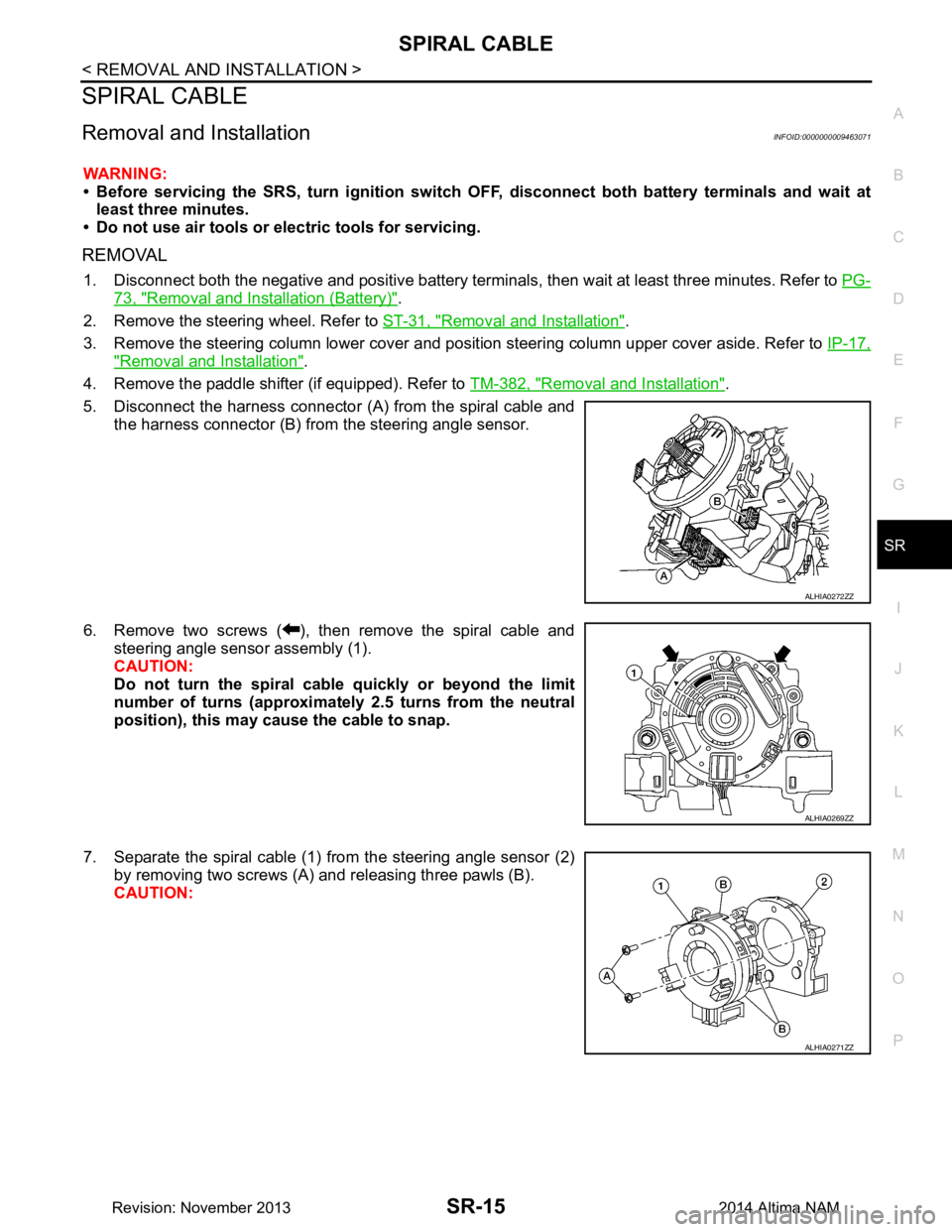
5. Disconnect the harness connector (A) from the spiral cable and the harness connector (B) from the steering angle sensor.
6. Remove two screws ( ), then remove the spiral cable and steering angle sensor assembly (1).
CAUTION:
Do not turn the spiral cable quickly or beyond the limit
number of turns (approximately 2.5 turns from the neutral
position), this may cause the cable to snap.
7. Separate the spiral cable (1) from the steering angle sensor (2) by removing two screws (A) and releasing three pawls (B).
CAUTION:
ALHIA0272ZZ
ALHIA0269ZZ
ALHIA0271ZZ
Revision: November 20132014 Altima NAM
Page 3978 of 4801
SR-16
< REMOVAL AND INSTALLATION >
SPIRAL CABLE
• Do not strike or drop the spiral cable.
• Replace the spiral cable if it has been dropped or sus-
tained an impact.
• Do not disassemble the spiral cable.
• Do not allow oil, grease, detergent or water to come in contact with the spiral cable.
INSTALLATION
Installation is in the reverse order of removal.
• The turn signal lever must be in the neutral position for spiral cable installation.
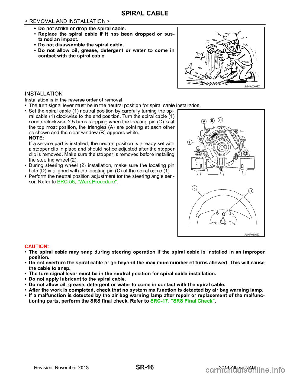
• Set the spiral cable (1) neutral position by carefully turning the spi-
ral cable (1) clockwise to the end position. Turn the spiral cable (1)
counterclockwise 2.5 turns stopping when the locating pin (C) is at
the top most position, the triangl es (A) are pointing at each other
as shown and the clear window (B) appears white.
NOTE:
If a service part is installed, the neutral position is already set with
a stopper clip in place and should not be adjusted after the stopper
clip is removed. Make sure the stopper is removed before installing
the steering wheel (2).
• During steering wheel (2) installation, make sure the locating pin hole (D) is aligned with the locating pin (C) of the spiral cable (1).
• Perform the neutral position adjustment for the steering angle sen-
sor. Refer to BRC-58, "Work Procedure"
.
CAUTION:
• The spiral cable may snap during steering operation if the spiral cable is installed in an improper
position.
• Do not overturn the spiral cable or go beyond the maximum number of turns allowed. This will cause
the cable to snap.
• The turn signal lever must be in the ne utral position for spiral cable installation.
• Do not apply lubricant to the spiral cable.
• Do not allow oil, grease, detergent or water to come in contact with the spiral cable.
• After the work is completed, check that no system malfunction is detected by air bag warning lamp.
• If a malfunction is detected by the air bag warnin g lamp after repair or replacement of the malfunc-
tioning parts, perform the SRS final check. Refer to SRC-17, "SRS Final Check"
.
JMHIA0009ZZ
ALHIA0270ZZ
Revision: November 20132014 Altima NAM
Page 3997 of 4801
SRC-4
< PRECAUTION >
PRECAUTIONS
PRECAUTION
PRECAUTIONS
Precaution for Supplemental Restraint System (SRS) "AIR BAG" and "SEAT BELT
PRE-TENSIONER"
INFOID:0000000009460702
The Supplemental Restraint System such as “A IR BAG” and “SEAT BELT PRE-TENSIONER”, used along
with a front seat belt, helps to reduce the risk or severi ty of injury to the driver and front passenger for certain
types of collision. Information necessary to service the system safely is included in the SR and SB section of
this Service Manual.
WARNING:
• To avoid rendering the SRS inopera tive, which could increase the risk of personal injury or death in
the event of a collision which would result in air bag inflation, all maintenance must be performed by
an authorized NISS AN/INFINITI dealer.
• Improper maintenance, including in correct removal and installation of the SRS, can lead to personal
injury caused by unintent ional activation of the system. For re moval of Spiral Cable and Air Bag
Module, see the SR section.
• Do not use electrical test equipmen t on any circuit related to the SRS unless instructed to in this
Service Manual. SRS wiring harn esses can be identified by yellow and/or orange harnesses or har-
ness connectors.
PRECAUTIONS WHEN USING POWER TOOLS (AIR OR ELECTRIC) AND HAMMERS
WARNING:
• When working near the Airbag Diagnosis Sensor Unit or other Airbag System sensors with the Igni-
tion ON or engine running, DO NOT use air or electri c power tools or strike near the sensor(s) with a
hammer. Heavy vibration could activate the sensor( s) and deploy the air bag(s), possibly causing
serious injury.
• When using air or electric power tools or hammers , always switch the Ignition OFF, disconnect the
battery and wait at least three minutes before performing any service.
Precaution for SRS "AIR BAG" and "S EAT BELT PRE-TENSIONER" Service
INFOID:0000000009460703
• Do not use electrical test equipment to check SRS ci rcuits unless instructed to in this Service Manual.
• Before servicing the SRS, turn ignition switch OFF, disconnect both battery cables and wait at least 3 min-
utes.
For approximately 3 minutes after the cables are removed, it is still possible for the air bag and seat belt pre-
tensioner to deploy. Therefore, do not work on any SR S connectors or wires until at least 3 minutes have
passed.
• The air bag diagnosis sensor unit must always be installed with the arrow mark “ ⇐” pointing toward the front
of the vehicle for proper operation. Also check air bag diagnosis sensor unit for cracks, deformities or rust
before installation and replace as required.
• The spiral cable must be aligned with the neutral position since its rotations are limited. Do not attempt to
turn steering wheel or column after removal of steering gear.
• Handle air bag module carefully. Always place driver and front passenger air bag modules with the pad side facing upward and seat mounted front side air bag m odule standing with the stud bolt side facing down.
• Conduct self-diagnosis to check entire SRS for proper function after replacing any components.
• After air bag inflates, the front instrument panel assembly should be replaced if damaged.
Revision: November 20132014 Altima NAMRevision: November 20132014 Altima NAM
Page 4000 of 4801
COMPONENT PARTSSRC-7
< SYSTEM DESCRIPTION >
C
D E
F
G
I
J
K L
M A
B
SRC
N
O P
Driver Air Bag ModuleINFOID:0000000009460706
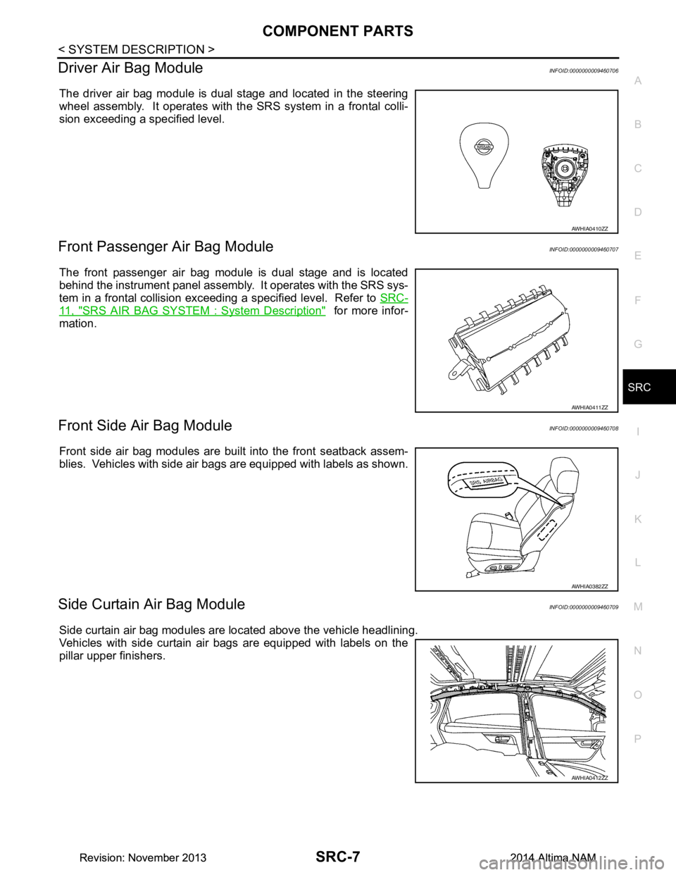
The driver air bag module is dual stage and located in the steering
wheel assembly. It operates with the SRS system in a frontal colli-
sion exceeding a specified level.
Front Passenger Air Bag ModuleINFOID:0000000009460707
The front passenger air bag module is dual stage and is located
behind the instrument panel assembly . It operates with the SRS sys-
tem in a frontal collision exceeding a specified level. Refer to SRC-
11, "SRS AIR BAG SYSTEM : System Description" for more infor-
mation.
Front Side Air Bag ModuleINFOID:0000000009460708
Front side air bag modules are built into the front seatback assem-
blies. Vehicles with side air bags are equipped with labels as shown.
Side Curtain Air Bag ModuleINFOID:0000000009460709
Side curtain air bag modules are located above the vehicle headlining.
Vehicles with side curtain air bags are equipped with labels on the
pillar upper finishers.
AWHIA0410ZZ
AWHIA0411ZZ
AWHIA0382ZZ
AWHIA0412ZZ
Revision: November 20132014 Altima NAMRevision: November 20132014 Altima NAM
Page 4104 of 4801

ST-1
STEERING
C
D E
F
H I
J
K L
M
SECTION ST
A
B
ST
N
O P
CONTENTS
STEERING SYSTEM
PRECAUTION ................ ...............................3
PRECAUTIONS .............................................. .....3
Precaution for Supplemental Restraint System
(SRS) "AIR BAG" and "SEAT BELT PRE-TEN-
SIONER" ............................................................. ......
3
Precaution for Steering System .......................... ......3
Precaution for Work ............................................ ......3
PREPARATION ............................................5
PREPARATION .............................................. .....5
Special Service Tool ........................................... ......5
Commercial Service Tool ..........................................5
SYSTEM DESCRIPTION ..............................7
COMPONENT PARTS ................................... .....7
HEATED STEERING WHEEL SYSTEM ............... ......7
HEATED STEERING WHEEL SYSTEM : Compo-
nent Parts Location ............................................. ......
7
HEATED STEERING WHEEL SYSTEM : Compo-
nent Description .................................................. ......
7
SYSTEM ..............................................................8
HEATED STEERING WHEEL SYSTEM ............... ......8
HEATED STEERING WHEEL SYSTEM : System
Diagram ............................................................... ......
8
HEATED STEERING WHEEL SYSTEM : System
Description .......................................................... ......
8
ECU DIAGNOSIS INFORMATION ...............9
A/C AUTO AMP. ............................................. .....9
List of ECU Reference ........................................ ......9
WIRING DIAGRAM ......................................10
HEATED STEERING WHEEL ........................ ....10
Wiring Diagram ................................................... ....10
BASIC INSPECTION ...................................13
DIAGNOSIS AND REPAIR WORK FLOW .......13
Work Flow ............................................................ ....13
POWER STEERING FLUID ..............................15
Inspection ................................................................15
STEERING WHEEL ..........................................16
Inspection ................................................................16
STEERING COLUMN ........................................18
Inspection ................................................................18
POWER STEERING OIL PUMP .......................19
Inspection ................................................................19
STEERING GEAR AND LINKAGE ...................20
Inspection ................................................................20
DTC/CIRCUIT DIAGNOSIS .........................21
POWER SUPPLY AND GROUND CIRCUIT ....21
A/C AUTO AMP. .................................................... ....21
A/C AUTO AMP. : Diagnosis Procedure .................21
HEATED STEERING WHEEL SYSTEM ...........22
Component Function Check ....................................22
Diagnosis Procedure ...............................................22
Component Inspection (Heated Steering Wheel
Switch) ................................................................. ....
24
Component Inspection (Heated Steering Relay) .....24
Component Inspection (Heated Steering Wheel) ....25
HEATED STEERING WHEEL SWITCH INDI-
CATOR LAMP ...................................................
26
Component Function Check ................................ ....26
Diagnosis Procedure ...............................................26
SYMPTOM DIAGNOSIS ..............................28
STEERING COLUMN ........................................28
Revision: November 20132014 Altima NAMRevision: November 20132014 Altima NAM
Page 4105 of 4801

ST-2
Symptom Table ......................................................28
NOISE, VIBRATION AND HARSHNESS
(NVH) TROUBLESHOOTING ......................... ...
29
NVH Troubleshooting Chart ................................ ...29
PERIODIC MAINTENANCE ..................... ...30
POWER STEERING FLUID ............................ ...30
Draining and Refilling .......................................... ...30
Air Bleeding Hydraulic System ...............................30
REMOVAL AND INSTAL LATION ...............31
STEERING WHEEL ........................................ ...31
Exploded View ..................................................... ...31
Removal and Installation ........................................31
STEERING COLUMN ........................................33
Exploded View ..................................................... ...33
Removal and Installation ........................................33
STEERING GEAR AND LINKAGE ....................36
Exploded View ..................................................... ...36
Removal and Installation ........................................36
POWER STEERING OIL PUMP ........................38
Exploded View ..................................................... ...38
Removal and Installation .........................................38
HYDRAULIC LINE .......................................... ...40
Exploded View ..................................................... ...40
Removal and Installation .........................................41
UNIT DISASSEMBLY AND ASSEMBLY ...43
STEERING GEAR AND LINKAGE ................ ...43
Exploded View ..................................................... ...43
Disassembly and Assembly ....................................43
POWER STEERING OIL PUMP ........................45
Disassembly and Assembly ................................. ...45
SERVICE DATA AND SPECIFICATIONS
(SDS) ............... ...........................................
46
SERVICE DATA AND SPECIFICATIONS
(SDS) .............................................................. ...
46
Steering Wheel .................................................... ...46
Steering Angle ........................................................46
Steering Column .....................................................46
Power Steering Gear ..............................................47
Power Steering Oil Pump ........................................48
Power Steering Fluid ...............................................48
Revision: November 20132014 Altima NAMRevision: November 20132014 Altima NAM
Page 4108 of 4801
PREPARATIONST-5
< PREPARATION >
C
D E
F
H I
J
K L
M A
B
ST
N
O P
PREPARATION
PREPARATION
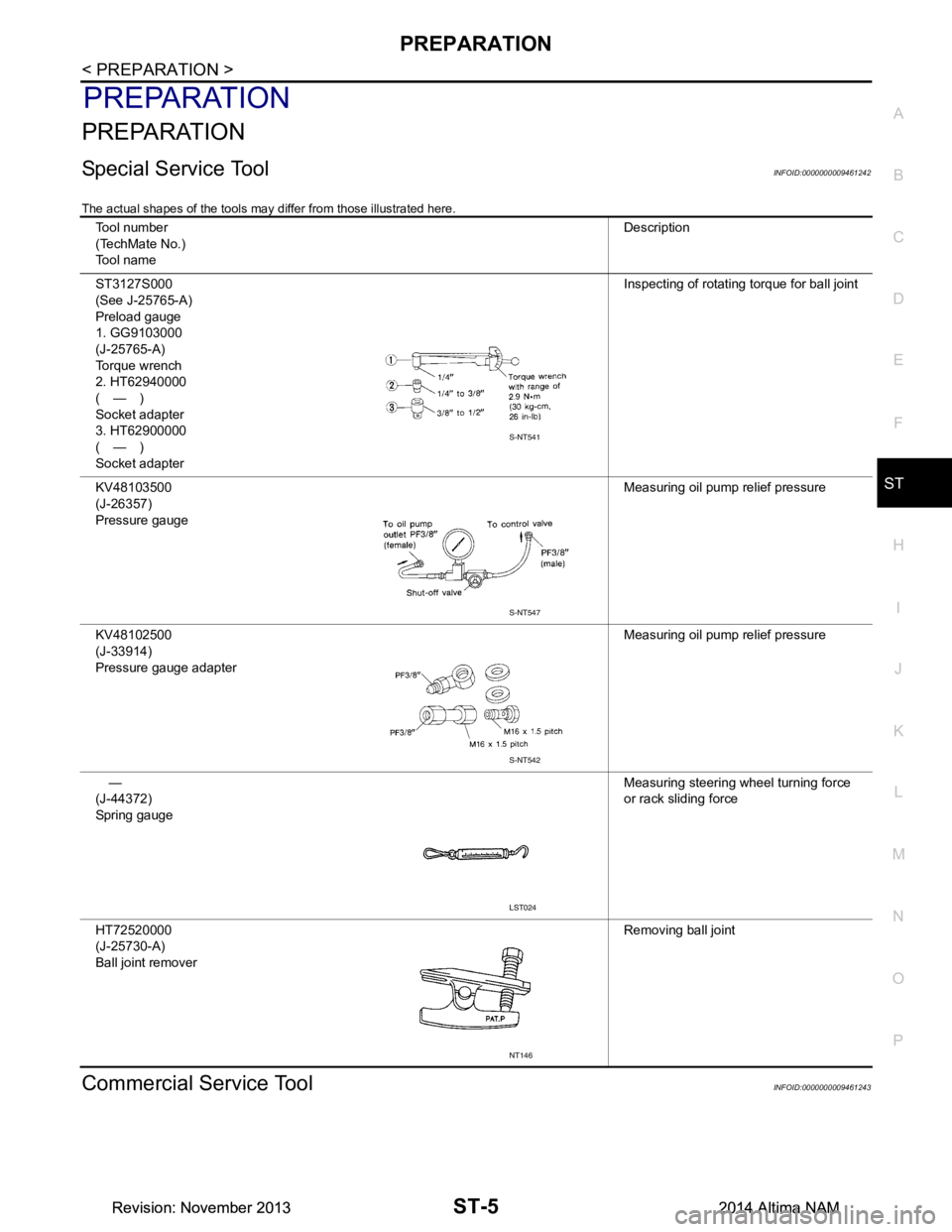
Special Service ToolINFOID:0000000009461242
The actual shapes of the tools may differ from those illustrated here.
Commercial Service ToolINFOID:0000000009461243
Tool number
(TechMate No.)
Tool name Description
ST3127S000
(See J-25765-A)
Preload gauge
1. GG9103000
(J-25765-A)
Torque wrench
2. HT62940000
(—)
Socket adapter
3. HT62900000
(—)
Socket adapter Inspecting of rotating torque for ball joint
KV48103500
(J-26357)
Pressure gauge Measuring oil pump relief pressure
KV48102500
(J-33914)
Pressure gauge adapter Measuring oil pump relief pressure
—
(J-44372)
Spring gauge Measuring steering wheel turning force
or rack sliding force
HT72520000
(J-25730-A)
Ball joint remover Removing ball joint
S-NT541
S-NT547
S-NT542
LST024
NT146
Revision: November 20132014 Altima NAMRevision: November 20132014 Altima NAM
Page 4109 of 4801
ST-6
< PREPARATION >
PREPARATION
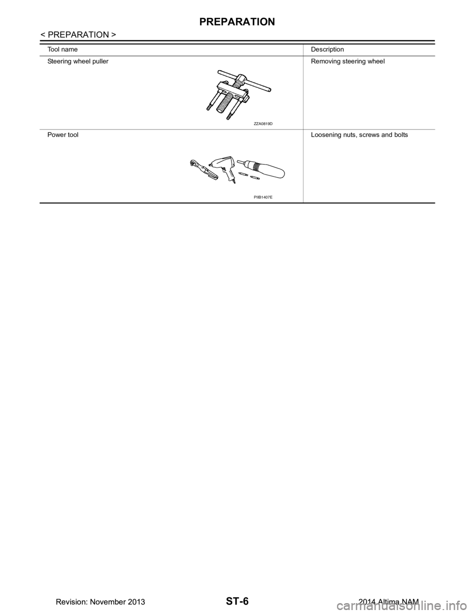
Tool nameDescription
Steering wheel puller Removing steering wheel
Power tool Loosening nuts, screws and bolts
ZZA0819D
PIIB1407E
Revision: November 20132014 Altima NAMRevision: November 20132014 Altima NAM