Page 4133 of 4801
ST-30
< PERIODIC MAINTENANCE >
POWER STEERING FLUID
PERIODIC MAINTENANCE
POWER STEERING FLUID
Draining and RefillingINFOID:0000000009461266
DRAINING
1. Disconnect the high and low pressure piping from power steering gear.
2. Drain power steering fluid into a suitable container.
REFILLING
1. Fill power steering reservoir while checking power steering fluid level.
2. Bleed air from power steering hydraulic system. Refer to ST-30, "Air Bleeding Hydraulic System"
.
3. Check for power steering fluid leaks.
Air Bleeding Hydraulic SystemINFOID:0000000009461267
AIR BLEEDING HYDRAULIC SYSTEM
If air bleeding is not complete, excessive noise in the power steering oil pump will be present.
1. Make sure engine is off.
2. Turn the steering wheel from the full right stop pos ition and then to full left stop position several times.
Repeat until bubbles are no longer being generated in the reservoir.
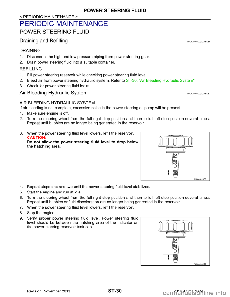
3. When the power steering fluid level lowers, refill the reservoir. CAUTION:
Do not allow the power steerin g fluid level to drop below
the hatching area.
4. Repeat steps one and two until the power steering fluid level stabilizes.
5. Start the engine and run at idle.
6. Turn the steering wheel from the full right stop pos ition and then to full left stop position several times.
Repeat until bubbles or fluid discoloration are no longer being generated in the reservoir.
7. When the power steering fluid level lowers, refill the reservoir.
8. Stop the engine.
9. Verify proper power steering fluid level. Power steering fluid level should be between the hatching area of the indicator on
the power steering reservoir tank cap.
ALGIA0125ZZ
ALGIA0125ZZ
Revision: November 20132014 Altima NAMRevision: November 20132014 Altima NAM
Page 4134 of 4801
STEERING WHEELST-31
< REMOVAL AND INSTALLATION >
C
D E
F
H I
J
K L
M A
B
ST
N
O P
REMOVAL AND INSTALLATION
STEERING WHEEL
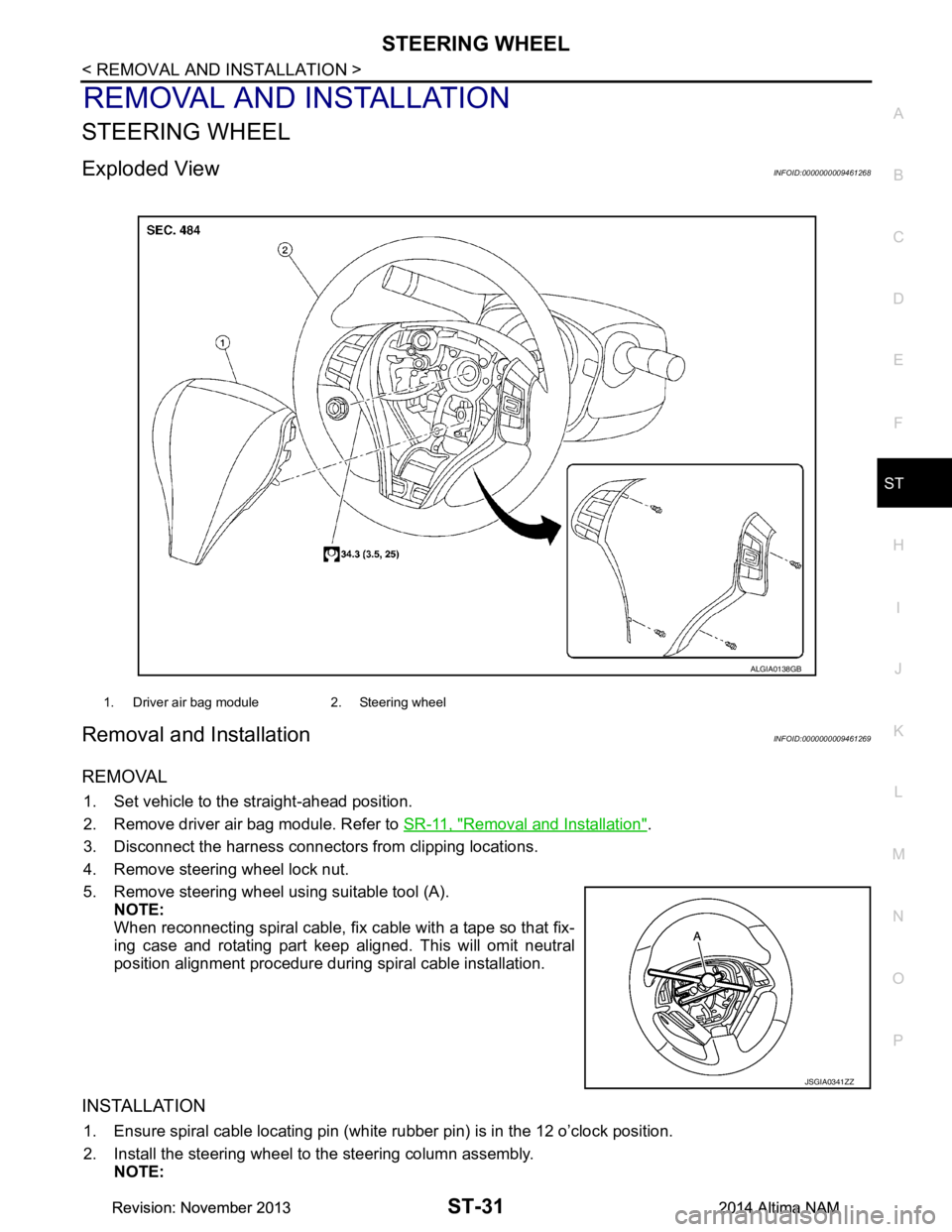
Exploded ViewINFOID:0000000009461268
Removal and InstallationINFOID:0000000009461269
REMOVAL
1. Set vehicle to the straight-ahead position.
2. Remove driver air bag module. Refer to SR-11, "Removal and Installation"
.
3. Disconnect the harness connectors from clipping locations.
4. Remove steering wheel lock nut.
5. Remove steering wheel using suitable tool (A). NOTE:
When reconnecting spiral cable, fix cable with a tape so that fix-
ing case and rotating part keep aligned. This will omit neutral
position alignment procedure during spiral cable installation.
INSTALLATION
1. Ensure spiral cable locating pin (white rubber pin) is in the 12 o’clock position.
2. Install the steering wheel to the steering column assembly. NOTE:
1. Driver air bag module 2. Steering wheel
ALGIA0138GB
JSGIA0341ZZ
Revision: November 20132014 Altima NAMRevision: November 20132014 Altima NAM
Page 4135 of 4801
ST-32
< REMOVAL AND INSTALLATION >
STEERING WHEEL
• Ensure tick mark on steering wheel is aligned with tick mark on the steering column pin.
• Ensure spiral cable location pin (white rubber pin) is aligned to the steering wheel locating pin hole.
• Route driver airbag module connector(s) and steer ing wheel heater connector harnesses through the
steering wheel.
3. Connect steering wheel switch connector to spiral cable.
4. Connect steering wheel heater connector (from spiral cable) to connector on steering wheel (if equipped).
5. Insert steering wheel heater harness into hook part of the steering wheel back cover.
Revision: November 20132014 Altima NAMRevision: November 20132014 Altima NAM
Page 4136 of 4801
STEERING COLUMNST-33
< REMOVAL AND INSTALLATION >
C
D E
F
H I
J
K L
M A
B
ST
N
O P
STEERING COLUMN
Exploded ViewINFOID:0000000009461270
Removal and InstallationINFOID:0000000009461271
REMOVAL
Hole Cover Seal, Hole Cove r and Lower Shaft Assembly
1. Set wheels to the straight-ahead position.
2. Remove the instrument lower panel LH. Refer to IP-14, "Exploded View"
.
3. Remove lower side bolt (A) of lower shaft assembly (1). • Steering gear (2)
1. Steering column assembly 2. Hole cover 3. Hole cover seal
4. Lower shaft assembly
AWGIA0219ZZ
ALGIA0147ZZ
Revision: November 20132014 Altima NAMRevision: November 20132014 Altima NAM
Page 4139 of 4801
ST-36
< REMOVAL AND INSTALLATION >
STEERING GEAR AND LINKAGE
STEERING GEAR AND LINKAGE
Exploded ViewINFOID:0000000009461272
Removal and InstallationINFOID:0000000009461273
NOTE:
When removing components such as hoses, tubes/lines, etc. , cap or plug openings to prevent fluid from spill-
ing.
REMOVAL
1. Remove the front wheels and tires using power tool. Refer to WT-55, "Adjustment".
2. Disconnect stabilizer connecting rods at st eering knuckles and reposition. Refer to FSU-19, "Exploded
View".
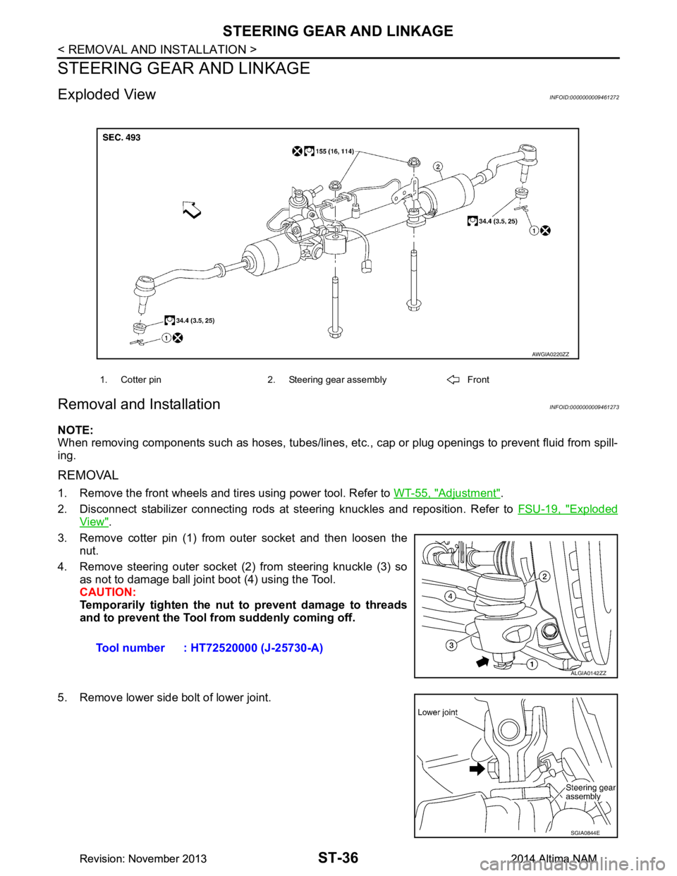
3. Remove cotter pin (1) from outer socket and then loosen the nut.
4. Remove steering outer socket (2) from steering knuckle (3) so as not to damage ball joint boot (4) using the Tool.
CAUTION:
Temporarily tighten the nut to prevent damage to threads
and to prevent the Tool fr om suddenly coming off.
5. Remove lower side bolt of lower joint.
1. Cotter pin 2. Steering gear assembly Front
AWGIA0220ZZ
Tool number : HT72520000 (J-25730-A)
ALGIA0142ZZ
SGIA0844E
Revision: November 20132014 Altima NAMRevision: November 20132014 Altima NAM
Page 4140 of 4801
STEERING GEAR AND LINKAGEST-37
< REMOVAL AND INSTALLATION >
C
D E
F
H I
J
K L
M A
B
ST
N
O P
6. Remove front exhaust tube. Refer to EX-5, "Exploded View" (QR25DE), EX-10, "Exploded View"
(VQ35DE).
7. Disconnect the high and low pressure piping from the steering gear assembly.
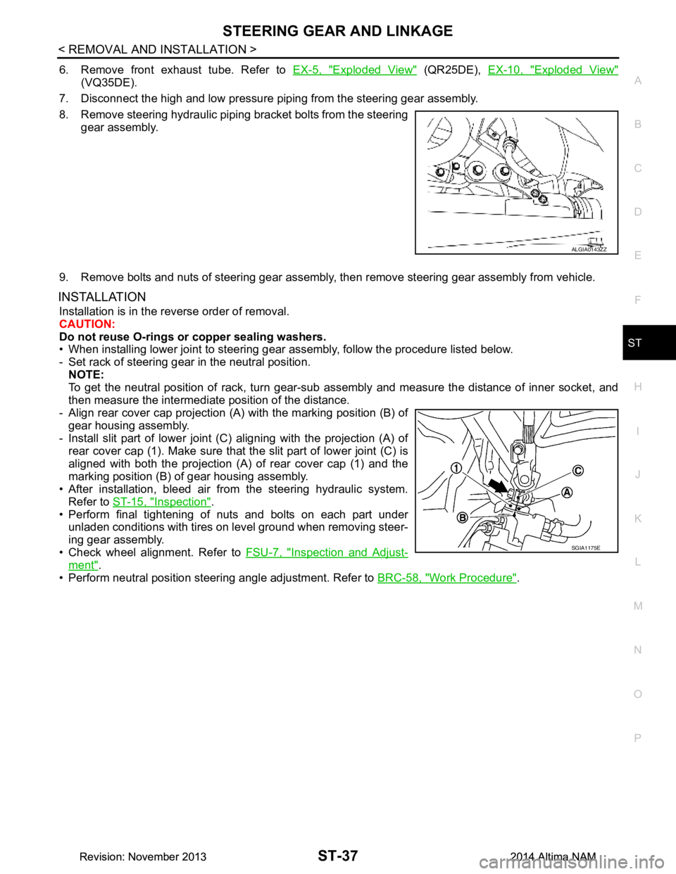
8. Remove steering hydraulic piping bracket bolts from the steering gear assembly.
9. Remove bolts and nuts of steering gear assembly, then remove steering gear assembly from vehicle.
INSTALLATION
Installation is in the reverse order of removal.
CAUTION:
Do not reuse O-rings or copper sealing washers.
• When installing lower joint to steering gear assembly, follow the procedure listed below.
- Set rack of steering gear in the neutral position. NOTE:
To get the neutral position of rack, turn gear-sub a ssembly and measure the distance of inner socket, and
then measure the intermediat e position of the distance.
- Align rear cover cap projection (A) with the marking position (B) of
gear housing assembly.
- Install slit part of lower joint (C) aligning with the projection (A) of
rear cover cap (1). Make sure that the slit part of lower joint (C) is
aligned with both the projection (A) of rear cover cap (1) and the
marking position (B) of gear housing assembly.
• After installation, bleed air from the steering hydraulic system. Refer to ST-15, "Inspection"
.
• Perform final tightening of nuts and bolts on each part under
unladen conditions with tires on level ground when removing steer-
ing gear assembly.
• Check wheel alignment. Refer to FSU-7, "Inspection and Adjust-
ment".
• Perform neutral position steering angle adjustment. Refer to BRC-58, "Work Procedure"
.
ALGIA0143ZZ
SGIA1175E
Revision: November 20132014 Altima NAMRevision: November 20132014 Altima NAM
Page 4149 of 4801
ST-46
< SERVICE DATA AND SPECIFICATIONS (SDS)
SERVICE DATA AND SPECIFICATIONS (SDS)
SERVICE DATA AND SPECIFICATIONS (SDS)
SERVICE DATA AND SPECIFICATIONS (SDS)
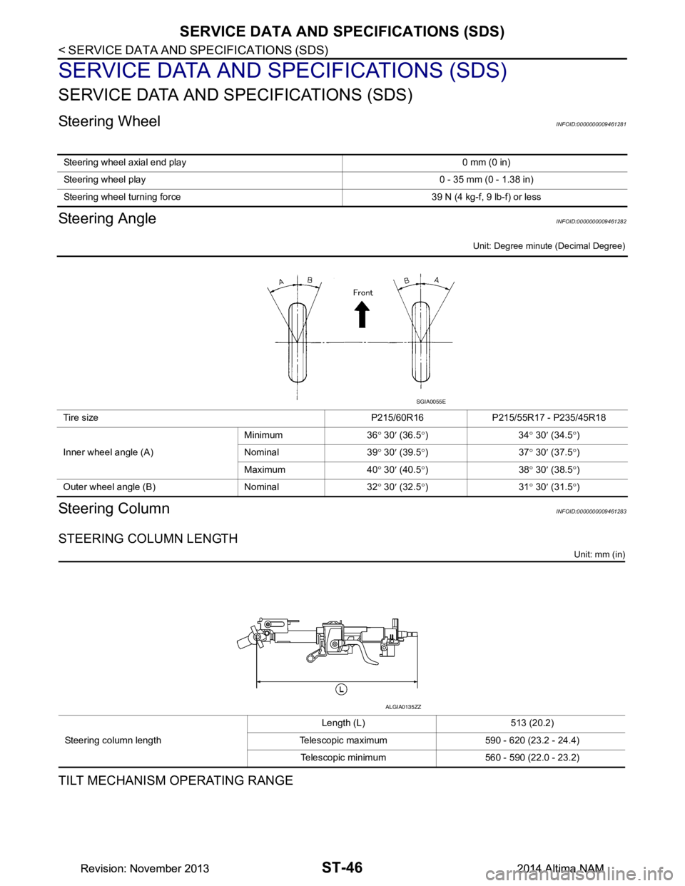
Steering WheelINFOID:0000000009461281
Steering AngleINFOID:0000000009461282
Unit: Degree minute (Decimal Degree)
Steering ColumnINFOID:0000000009461283
STEERING COLUMN LENGTH
Unit: mm (in)
TILT MECHANISM OPERATING RANGE
Steering wheel axial end play 0 mm (0 in)
Steering wheel play 0 - 35 mm (0 - 1.38 in)
Steering wheel turning force 3 9 N (4 kg-f, 9 lb-f) or less
Tire size P215/60R16 P215/55R17 - P235/45R18
Inner wheel angle (A) Minimum 36
° 30 ′ (36.5 °)34 ° 30 ′ (34.5 °)
Nominal 39 ° 30 ′ (39.5 °)37 ° 30 ′ (37.5 °)
Maximum 40 ° 30 ′ (40.5 °)38 ° 30 ′ (38.5 °)
Outer wheel angle (B) Nominal 32 ° 30 ′ (32.5 °)31 ° 30 ′ (31.5 °)
SGIA0055E
Steering column length Length (L) 513 (20.2)
Telescopic maximum 590 - 620 (23.2 - 24.4) Telescopic minimum 560 - 590 (22.0 - 23.2)
ALGIA0135ZZ
Revision: November 20132014 Altima NAMRevision: November 20132014 Altima NAM
Page 4153 of 4801

STC-2
Component Function Check ...................................31
Diagnosis Procedure ..............................................31
SYMPTOM DIAGNOSIS .............................32
HYDRAULIC PUMP ELECTRIC POWER
STEERING WARN ING LAMP DOES NOT
TURN ON ........................................................ ...
32
Description ........................................................... ...32
Diagnosis Procedure ..............................................32
HYDRAULIC PUMP ELECTRIC POWER
STEERING WARN ING LAMP DOES NOT
TURN OFF ...................................................... ...
33
Description ........................................................... ...33
Diagnosis Procedure ..............................................33
STEERING WHEEL TURNING FORCE IS
HEAVY OR LIGHT .......................................... ...
34
Diagnosis Procedure ............................................ ...34
UNBALANCE STEERING WHEEL TURNING
FORCE AND RETURN BETWEEN RIGHT
AND LEFT ...................................................... ...
36
Diagnosis Procedure ............................................ ...36
UNBALANCE STEERING WHEEL TURNING
FORCE (TORQUE VARIATION) .................... ...
37
Diagnosis Procedure ............................................ ...37
UNIT REMOVAL AND INSTALLATION ....39
POWER STEERING CONTROL MODULE .......39
Removal and Installation .........................................39
Revision: November 20132014 Altima NAMRevision: November 20132014 Altima NAM