2014 NISSAN TEANA steering wheel
[x] Cancel search: steering wheelPage 4180 of 4801

C160A HEAT PROTECTIONSTC-29
< DTC/CIRCUIT DIAGNOSIS >
C
D E
F
H I
J
K L
M A
B
STC
N
O P
C160A HEAT PROTECTION
DTC LogicINFOID:0000000009460366
DTC DETECTION LOGIC
DTC CONFIRMATION PROCEDURE
1.PRECONDITIONING
If “DTC CONFIRMATION PROCEDURE” has been previously conducted, always turn ignition switch OFF and
wait at least 10 seconds before conducting the next test.
>> GO TO 2.
2.DTC REPRODUCTION PROCEDURE
With CONSULT
1. Turn the ignition switch OFF to ON.
2. Perform “EPS” self-diagnosis.
Is DTC
“C160A” detected?
YES >> Go to STC-19, "Work Flow".
NO >> Inspection End.
DTC Display item Malfunction detected condition Possible cause
C160A HEAT PROTECTION When the steering wheel is operated excessively
and the interior temperature of the power steering
system reaches 118 °C (244.4 °F) or more. (Protec-
tion function)
NOTE:
Although the hydraulic pump electric power steering
system warning lamp turns ON, this is not a system
malfunction. The state returns to normal after stop-
ping steering operation and waiting until the system
interior temperature drops to 90 °C (194 °F) or less. The protection of the hydraulic
pump electric power steering sys-
tem
Revision: November 20132014 Altima NAMRevision: November 20132014 Altima NAM
Page 4185 of 4801

STC-34
< SYMPTOM DIAGNOSIS >
STEERING WHEEL TURNING FORCE IS HEAVY OR LIGHT
STEERING WHEEL TURNING FORCE IS HEAVY OR LIGHT
Diagnosis ProcedureINFOID:0000000009460376
1.PERFORM SELF-DIAGNOSIS
With CONSULT
Perform “EPS” self-diagnosis.
Is a malfunctioning system displayed?
YES >> Check malfunctioning system. Refer to STC-13, "DTC Index".
NO >> GO TO 2.
2.CHECK THE POWER STEERING CONTROL MODULE SIGNAL (1)
With CONSULT
1. Start the engine. CAUTION:
Never drive the vehicle.
2. Turn the steering wheel until it stops.
3. Select “MTR ASSIST” in “DATA MONITOR” of “EPS”.
Is the display value
“100%”?
YES >> GO TO 4.
NO >> GO TO 3.
3.CHECK THE POWER STEERING CONTROL MODULE SIGNAL (2)
With CONSULT
1. Select “C/U TEMP” and “C/U TEMP A” in “DATA MONITOR” of “EPS”.
2. Stop the system until the DATA MONITOR display value drops to “90 °C (194 °F)” or less.
3. Check whether symptom continues.
Did symptom continue?
YES >> GO TO 4.
NO >> This occurs because the protection function lowers the assist force. It is not a system malfunction.
Inspection End.
4.CHECK THE POWER STEERING CONTROL MODULE SIGNAL (3)
With CONSULT
1. Turn the steering wheel to the straight -ahead position. (There is no steering force)
2. Select “BATTERY VOLT” in “DATA MONITOR” of “EPS”.
Is the display value
“10.5 V” or more?
YES >> GO TO 5.
NO >> Check the battery power system. Refer to STC-23, "Diagnosis Procedure"
.
5.CHECK THE POWER STEERING CONTROL MODULE SIGNAL (4)
With CONSULT
Select “ESTM VHCL SPD” in “DATA MONITOR” of “EPS”.
*: This may not agree with the speedometer indication imm ediately after the ignition switch is turned ON. This
is not a malfunction.
Is the check result normal?
YES >> GO TO 6.
NO >> Check the combination meter, ABS actuator and electric unit (control unit). Refer to MWI-18,
"CONSULT Function (METER/M&A)" and BRC-33, "CONSULT Function (ABS)".
Monitor item Test condition Display value
ESTM VHCL SPD When stopped 0.00 km/h or mph
While driving Approximately equal to the in-
dication on speedometer
*
(Inside of ±10%)
Revision: November 20132014 Altima NAMRevision: November 20132014 Altima NAM
Page 4186 of 4801

STEERING WHEEL TURNING FORCE IS HEAVY OR LIGHTSTC-35
< SYMPTOM DIAGNOSIS >
C
D E
F
H I
J
K L
M A
B
STC
N
O P
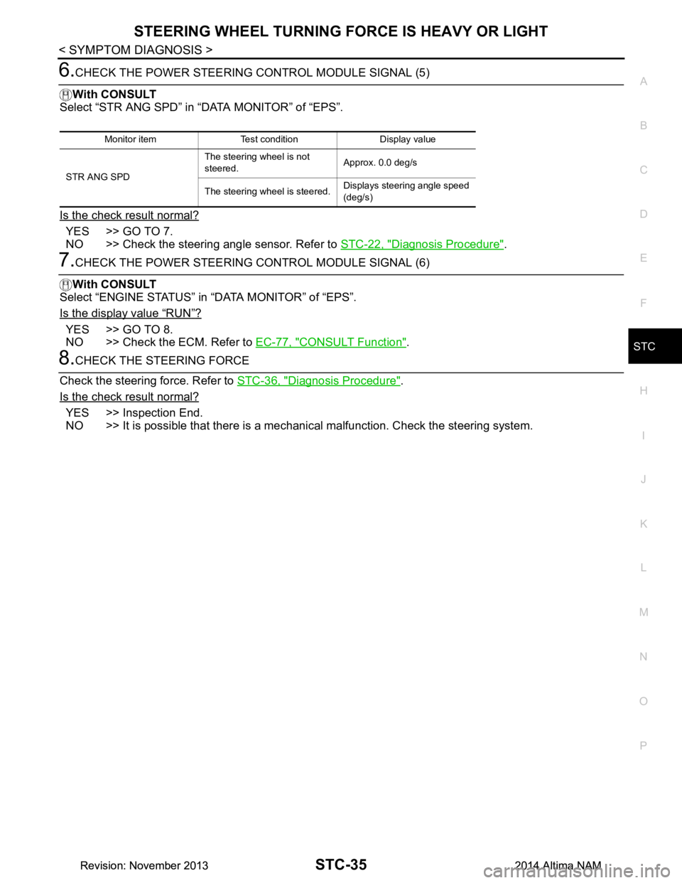
6.CHECK THE POWER STEERING CONTROL MODULE SIGNAL (5)
With CONSULT
Select “STR ANG SPD” in “DATA MONITOR” of “EPS”.
Is the check result normal?
YES >> GO TO 7.
NO >> Check the steering angle sensor. Refer to STC-22, "Diagnosis Procedure"
.
7.CHECK THE POWER STEERING CONTROL MODULE SIGNAL (6)
With CONSULT
Select “ENGINE STATUS” in “DATA MONITOR” of “EPS”.
Is the display value
“RUN”?
YES >> GO TO 8.
NO >> Check the ECM. Refer to EC-77, "CONSULT Function"
.
8.CHECK THE STEERING FORCE
Check the steering force. Refer to STC-36, "Diagnosis Procedure"
.
Is the check result normal?
YES >> Inspection End.
NO >> It is possible that there is a mechani cal malfunction. Check the steering system.
Monitor item Test condition Display value
STR ANG SPD The steering wheel is not
steered. Approx. 0.0 deg/s
The steering wheel is steered. Displays steering angle speed
(deg/s)
Revision: November 20132014 Altima NAMRevision: November 20132014 Altima NAM
Page 4187 of 4801

STC-36
< SYMPTOM DIAGNOSIS >
UNBALANCE STEERING WHEEL TURNING FORCE AND RETURN BETWEEN
RIGHT AND LEFT
UNBALANCE STEERING WHEEL TU RNING FORCE AND RETURN BE-
TWEEN RIGHT AND LEFT
Diagnosis ProcedureINFOID:0000000009460377
1.CHECK THE ILLUMINATION OF THE HYDRAULIC PUMP ELECTRIC POWER STEERING WARNING
LAMP
Check the hydraulic pump electric power steering warning lamp while engine is running.
Does the hydraulic pump electric power steering warning lamp turn OFF?
YES >> GO TO 2.
NO >> Refer to STC-33, "Diagnosis Procedure"
.
2.CHECK WHEEL ALIGNMENT
Check the wheel alignment. Refer to FSU-25, "Wheel Alignment (Unladen*
1)".
Is the inspection result normal?
YES >> GO TO 3.
NO >> Adjustment of wheel alignment. Refer to FSU-25, "Wheel Alignment (Unladen*
1)".
3.CHECK STEERING WHEEL TURNING FORCE
Check the steering wheel turning force. Refer to STC-37, "Diagnosis Procedure"
.
Is the inspection result normal?
YES >> Inspection End.
NO >> Check the steering wheel turning force for mechanical malfunction. Refer to STC-34, "Diagnosis
Procedure".
Revision: November 20132014 Altima NAMRevision: November 20132014 Altima NAM
Page 4188 of 4801

UNBALANCE STEERING WHEEL TURNING FORCE (TORQUE VARIATION)
STC-37
< SYMPTOM DIAGNOSIS >
C
D E
F
H I
J
K L
M A
B
STC
N
O P
UNBALANCE STEERING WHEEL TU RNING FORCE (TORQUE VARIA-
TION)
Diagnosis ProcedureINFOID:0000000009460378
1.PERFORM SELF-DIAGNOSIS
With CONSULT
Perform “EPS” self-diagnosis.
Is a malfunctioning system displayed?
YES >> Check malfunctioning system. Refer to STC-13, "DTC Index".
NO >> GO TO 2.
2.CHECK THE POWER STEERING CONTROL MODULE SIGNAL (1)
With CONSULT
1. Start the engine. CAUTION:
Never drive the vehicle.
2. Turn the steering wheel until it stops.
3. Select “MTR ASSIST” in “DATA MONITOR” of “EPS”.
Is the display value
“100%”?
YES >> GO TO 4.
NO >> GO TO 3.
3.CHECK THE POWER STEERING CONTROL MODULE SIGNAL (2)
With CONSULT
1. Select “C/U TEMP” and “C/U TEMP A” in “DATA MONITOR” of “EPS”.
2. Stop the system until the DATA MONITOR display value drops to “90 °C (194 °F)” or less.
3. Check whether symptom continues.
Did symptom continue?
YES >> GO TO 4.
NO >> This occurs because the protection function lowers the assist force. It is not a system malfunction.
Inspection End.
4.CHECK THE POWER STEERING CONTROL MODULE SIGNAL (3)
With CONSULT
1. Turn the steering wheel to the straight -ahead position. (There is no steering force.)
2. Select “BATTERY VOLT” in “DATA MONITOR” of “EPS”.
Is the display value
“10.5 V” or more?
YES >> GO TO 5.
NO >> Check the battery power system. Refer to STC-23, "Diagnosis Procedure"
.
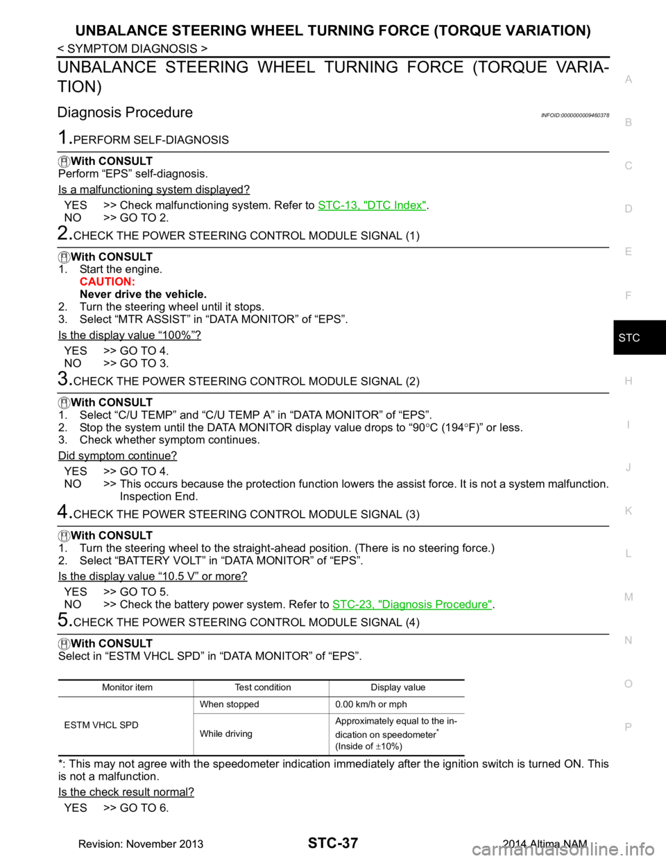
5.CHECK THE POWER STEERING CONTROL MODULE SIGNAL (4)
With CONSULT
Select in “ESTM VHCL SPD” in “DATA MONITOR” of “EPS”.
*: This may not agree with the speedometer indication immediately after the ignition switch is turned ON. This
is not a malfunction.
Is the check result normal?
YES >> GO TO 6.
Monitor item Test condition Display value
ESTM VHCL SPD When stopped 0.00 km/h or mph
While driving Approximately equal to the in-
dication on speedometer
*
(Inside of ±10%)
Revision: November 20132014 Altima NAMRevision: November 20132014 Altima NAM
Page 4189 of 4801

STC-38
< SYMPTOM DIAGNOSIS >
UNBALANCE STEERING WHEEL TURNING FORCE (TORQUE VARIATION)
NO >> Check the combination meter, ABS actuator and electric unit (control unit). Refer to MWI-18,
"CONSULT Function (METER/M&A)" and BRC-33, "CONSULT Function (ABS)".
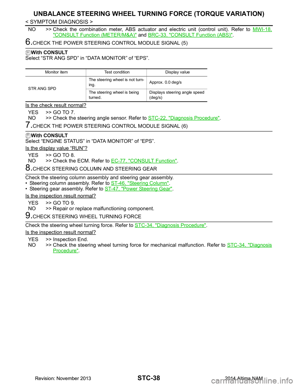
6.CHECK THE POWER STEERING CONTROL MODULE SIGNAL (5)
With CONSULT
Select “STR ANG SPD” in “DATA MONITOR” of “EPS”.
Is the check result normal?
YES >> GO TO 7.
NO >> Check the steering angle sensor. Refer to STC-22, "Diagnosis Procedure"
.
7.CHECK THE POWER STEERING CONTROL MODULE SIGNAL (6)
With CONSULT
Select “ENGINE STATUS” in “DATA MONITOR” of “EPS”.
Is the display value
“RUN”?
YES >> GO TO 8.
NO >> Check the ECM. Refer to EC-77, "CONSULT Function"
.
8.CHECK STEERING COLUMN AND STEERING GEAR
Check the steering column assembly and steering gear assembly.
• Steering column assembly. Refer to ST-46, "Steering Column"
.
• Steering gear assembly. Refer to ST-47, "Power Steering Gear"
.
Is the inspection result normal?
YES >> GO TO 9.
NO >> Repair or replace malfunctioning component.
9.CHECK STEERING WHEEL TURNING FORCE
Check the steering wheel turning force. Refer to STC-34, "Diagnosis Procedure"
.
Is the inspection result normal?
YES >> Inspection End.
NO >> Check the steering wheel turning force for mechanical malfunction. Refer to STC-34, "Diagnosis
Procedure".
Monitor item Test condition Display value
STR ANG SPD The steering wheel is not turn-
ing. Approx. 0.0 deg/s
The steering wheel is being
turned. Displays steering angle speed
(deg/s)
Revision: November 20132014 Altima NAMRevision: November 20132014 Altima NAM
Page 4597 of 4801
![NISSAN TEANA 2014 Service Manual
TM-382
< REMOVAL AND INSTALLATION >[CVT: RE0F10E]
PADDLE SHIFTER
PADDLE SHIFTER
Exploded ViewINFOID:0000000009464338
Removal and InstallationINFOID:0000000009464339
REMOVAL
1. Park the vehicle on a l NISSAN TEANA 2014 Service Manual
TM-382
< REMOVAL AND INSTALLATION >[CVT: RE0F10E]
PADDLE SHIFTER
PADDLE SHIFTER
Exploded ViewINFOID:0000000009464338
Removal and InstallationINFOID:0000000009464339
REMOVAL
1. Park the vehicle on a l](/manual-img/5/57390/w960_57390-4596.png)
TM-382
< REMOVAL AND INSTALLATION >[CVT: RE0F10E]
PADDLE SHIFTER
PADDLE SHIFTER
Exploded ViewINFOID:0000000009464338
Removal and InstallationINFOID:0000000009464339
REMOVAL
1. Park the vehicle on a level surface.
2. Remove the driver air bag module. Refer to SR-11, "Removal and Installation"
.
3. Remove the steering wheel. Refer to ST-31, "Removal and Installation"
.
4. Remove the column cover. Refer to IP-17, "Removal and Installation"
.
1. Steering column assembly 2. Paddle shifter (shift-down) 3. Paddle shifter (shift-up)
AWDIA0557GB
Revision: November 20132014 Altima NAMRevision: November 20132014 Altima NAM
Page 4727 of 4801

WT-52
< SYMPTOM DIAGNOSIS >
NOISE, VIBRATION AND HARSHNESS (NVH) TROUBLESHOOTING
NOISE, VIBRATION AND HARSHNESS (NVH) TROUBLESHOOTING
NVH Troubleshooting ChartINFOID:0000000009464519
Use chart below to help you find the cause of the symp tom. If necessary, repair or replace these parts.
×: ApplicableReference page
WT-55, "Adjustment"WT-53, "Inspection"WT-55, "Adjustment"
WT-60, "Tire"
—
—
—
WT-60, "Tire"
FAX-5, "NVH Troubleshooting Chart"
,
FSU-6, "NVH Troubleshooting Chart"
RAX-4, "NVH Troubleshooting Chart"
,
RSU-4, "NVH Troubleshooting Chart"
Refer to TIRES in this chart.
Refer to ROAD WHEEL in this chart.
FAX-5, "NVH Troubleshooting Chart"
BR-6, "NVH Troubleshooting Chart"ST-29, "NVH Troubleshooting Chart"
Possible cause and SUSPECTED
PA R T S
Improper installation, looseness
Out-of-round
Imbalance
Incorrect tire pressure
Uneven tire wear
Deformation or damage
Non-uniformity
Incorrect tire size
FRONT AXLE AND FRONT SUSPENSION
REAR AXLE AND REAR SUSPENSION
TIRES
ROAD WHEELS
DRIVE SHAFT
BRAKE
STEERING
Symptom TIRESNoise
××××××× × × ××××
Shake ×××××× × × × ××××
Vibration ××××××
Shimmy ×××××××× × × × ××
Shudder ×××××× × × × × ××
Poor quality ride
or handling ×××××× × × ××
ROAD
WHEEL Noise
×× × × × × × × × ×
Shake ×× × × × × × × × ×
Shimmy, Shud-
der ×××× ×××××
Poor quality ride
or handling ×× × × × × ×
Revision: November 20132014 Altima NAMRevision: November 20132014 Altima NAM