2014 NISSAN TEANA steering wheel
[x] Cancel search: steering wheelPage 3189 of 4801
GENERAL MAINTENANCEMA-5
< PERIODIC MAINTENANCE >
C
D E
F
G H
I
J
K L
M B
MA
N
O A
PERIODIC MAINTENANCE
GENERAL MAINTENANCE
FOR USA AND CANADA
FOR USA AND CANADA : Explana
tion of General MaintenanceINFOID:0000000009464530
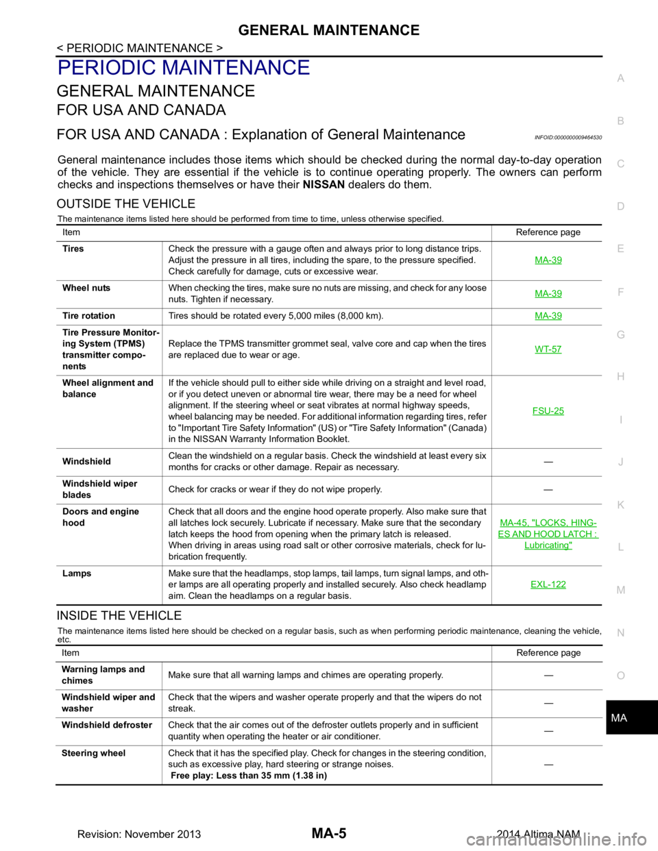
General maintenance includes those items which shoul d be checked during the normal day-to-day operation
of the vehicle. They are essential if the vehicle is to continue operating properly. The owners can perform
checks and inspections themselves or have their NISSAN dealers do them.
OUTSIDE THE VEHICLE
The maintenance items listed here should be performed from time to time, unless otherwise specified.
INSIDE THE VEHICLE
The maintenance items listed here should be checked on a regular basis, such as when performing periodic maintenance, cleaning the vehicle,
etc.
Item Reference page
Tires Check the pressure with a gauge often and always prior to long distance trips.
Adjust the pressure in all tires, including the spare, to the pressure specified.
Check carefully for damage, cuts or excessive wear. MA-39
Wheel nuts
When checking the tires, make sure no nuts are missing, and check for any loose
nuts. Tighten if necessary. MA-39
Tire rotation
Tires should be rotated every 5,000 miles (8,000 km). MA-39
Tire Pressure Monitor-
ing System (TPMS)
transmitter compo-
nents Replace the TPMS transmitter grommet seal, valve core and cap when the tires
are replaced due to wear or age. WT-57
Wheel alignment and
balance If the vehicle should pull to either side while driving on a straight and level road,
or if you detect uneven or abnormal tire wear, there may be a need for wheel
alignment. If the steering wheel or seat vibrates at normal highway speeds,
wheel balancing may be needed. For additional information regarding tires, refer
to "Important Tire Safety Information" (US) or "Tire Safety Information" (Canada)
in the NISSAN Warranty Information Booklet. FSU-25
Windshield
Clean the windshield on a regular basis. Check the windshield at least every six
months for cracks or other damage. Repair as necessary. —
Windshield wiper
blades Check for cracks or wear if they do not wipe properly. —
Doors and engine
hood Check that all doors and the engine hood operate properly. Also make sure that
all latches lock securely. Lubricate if necessary. Make sure that the secondary
latch keeps the hood from opening when the primary latch is released.
When driving in areas using road salt or other corrosive materials, check for lu-
brication frequently. MA-45, "LOCKS, HING-
ES AND HOOD LATCH :
Lubricating"
Lamps
Make sure that the headlamps, stop lamps, tail lamps, turn signal lamps, and oth-
er lamps are all operating properly and installed securely. Also check headlamp
aim. Clean the headlamps on a regular basis. EXL-122
Item
Reference page
Warning lamps and
chimes Make sure that all warning lamps and chimes are operating properly. —
Windshield wiper and
washer Check that the wipers and washer operate properly and that the wipers do not
streak. —
Windshield defroster Check that the air comes out of the defroster outlets properly and in sufficient
quantity when operating the heater or air conditioner. —
Steering wheel Check that it has the specified play. Check for changes in the steering condition,
such as excessive play, hard steering or strange noises.
Free play: Less than 35 mm (1.38 in) —
Revision: November 20132014 Altima NAM
Page 3228 of 4801
MA-44
< PERIODIC MAINTENANCE >
CHASSIS AND BODY MAINTENANCE
POWER STEERING FLUID AND LINES : Inspection
INFOID:0000000009464588
FLUID LEVEL
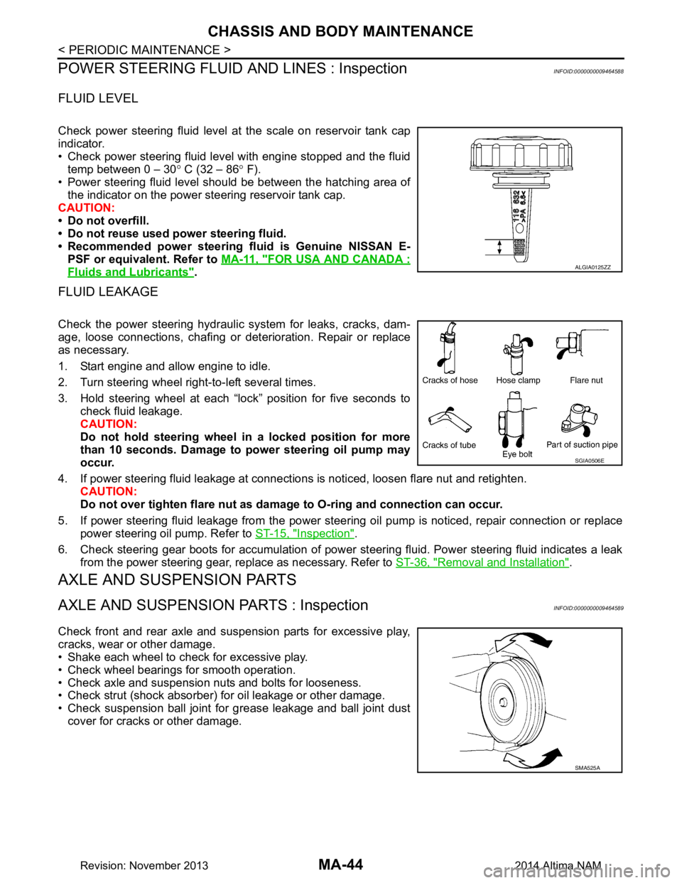
Check power steering fluid level at the scale on reservoir tank cap
indicator.
• Check power steering fluid level with engine stopped and the fluid temp between 0 – 30 ° C (32 – 86 ° F).
• Power steering fluid level should be between the hatching area of the indicator on the power steering reservoir tank cap.
CAUTION:
• Do not overfill.
• Do not reuse used power steering fluid.
• Recommended power steering fluid is Genuine NISSAN E-
PSF or equivalent. Refer to MA-11, "FOR USA AND CANADA :
Fluids and Lubricants".
FLUID LEAKAGE
Check the power steering hydraulic system for leaks, cracks, dam-
age, loose connections, chafing or det erioration. Repair or replace
as necessary.
1. Start engine and allow engine to idle.
2. Turn steering wheel right-to-left several times.
3. Hold steering wheel at each “lock” position for five seconds to check fluid leakage.
CAUTION:
Do not hold steering wheel in a locked position for more
than 10 seconds. Damage to power steering oil pump may
occur.
4. If power steering fluid leakage at connections is noticed, loosen flare nut and retighten.
CAUTION:
Do not over tighten flare nut as damage to O-ring and connection can occur.
5. If power steering fluid leakage from the power steer ing oil pump is noticed, repair connection or replace
power steering oil pump. Refer to ST-15, "Inspection"
.
6. Check steering gear boots for accumulation of power steering fluid. Power steering fluid indicates a leak from the power steering gear, replace as necessary. Refer to ST-36, "Removal and Installation"
.
AXLE AND SUSPENSION PARTS
AXLE AND SUSPENSION PARTS : InspectionINFOID:0000000009464589
Check front and rear axle and suspension parts for excessive play,
cracks, wear or other damage.
• Shake each wheel to check for excessive play.
• Check wheel bearings for smooth operation.
• Check axle and suspension nuts and bolts for looseness.
• Check strut (shock absorber) for oil leakage or other damage.
• Check suspension ball joint for grease leakage and ball joint dust cover for cracks or other damage.
ALGIA0125ZZ
SGIA0506E
SMA525A
Revision: November 20132014 Altima NAM
Page 3325 of 4801
MWI-70
< DTC/CIRCUIT DIAGNOSIS >
STEERING SWITCH
STEERING SWITCH
DescriptionINFOID:0000000009461735
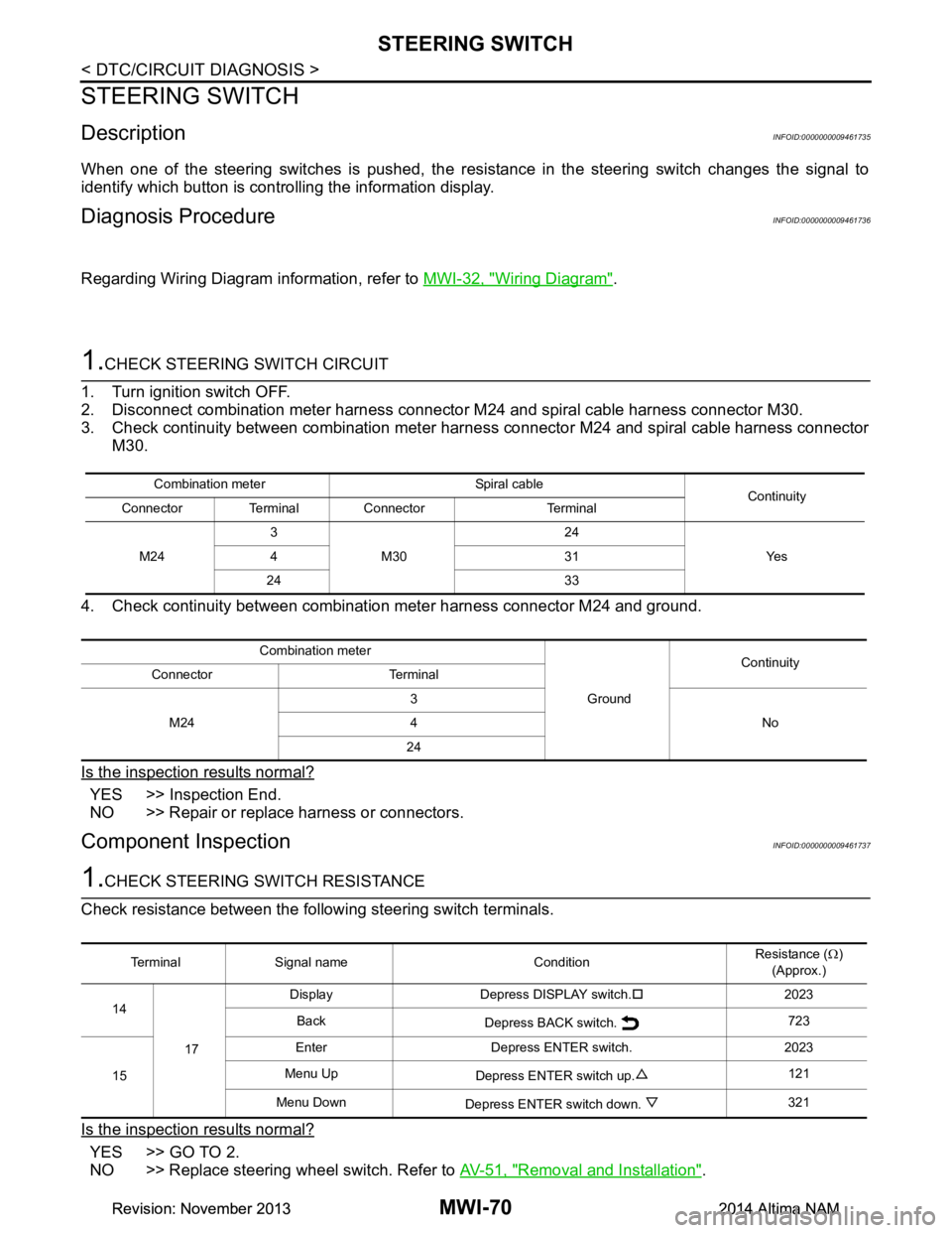
When one of the steering switches is pushed, the resistance in the steering switch changes the signal to
identify which button is controlling the information display.
Diagnosis ProcedureINFOID:0000000009461736
Regarding Wiring Diagram information, refer to MWI-32, "Wiring Diagram".
1.CHECK STEERING SWITCH CIRCUIT
1. Turn ignition switch OFF.
2. Disconnect combination meter harness connector M24 and spiral cable harness connector M30.
3. Check continuity between combination meter har ness connector M24 and spiral cable harness connector
M30.
4. Check continuity between combination meter harness connector M24 and ground.
Is the inspection results normal?
YES >> Inspection End.
NO >> Repair or replace harness or connectors.
Component InspectionINFOID:0000000009461737
1.CHECK STEERING SWITCH RESISTANCE
Check resistance between the following steering switch terminals.
Is the inspection results normal?
YES >> GO TO 2.
NO >> Replace steering wheel switch. Refer to AV-51, "Removal and Installation"
.
Combination meter Spiral cable
Continuity
Connector Terminal Connector Terminal
M24 3
M30 24
Ye s
431
24 33
Combination meter GroundContinuity
Connector Terminal
M24 3
No
4
24
Terminal Signal name Condition Resistance (
Ω)
(Approx.)
14
17 Display Depress DISPLAY switch.
�†2023
Back Depress BACK switch. 723
15 Enter Depress ENTER switch. 2023
Menu Up Depress ENTER switch up. 121
Menu Down Depress ENTER switch down. 321
Revision: November 20132014 Altima NAMRevision: November 20132014 Altima NAM
Page 3474 of 4801

PG-42
< DTC/CIRCUIT DIAGNOSIS >
HARNESS
B3 M51 L/8 : Heated steering wheel switch D2 M153 W / 2 4: AV control unit (With navigation system
with BOSE audio system)
C3 M52 W/2 : Combination switch (Spiral cable) A3 M155 W/4 : Joint connector-M06
C3 M53 W/8 : Steering angle sensor C3 M156 W/4 : Joint connector-M07
D2 M54 W/4 : Hazard switch D3 M157 W/4 : Joint connector-M08
A1 M55 BR/2 : Front speaker LH B3 M158 W/8 : Meter control switch
B1 M56 B/2 : Sunload sensor D1 M159 W/4 : Dongle unit
B2 M57 — : Body ground Console sub-harness
E3 M58 W/40 : ITS control unit D4 M201 W/6 : Front heated seat switch LH
E3 M59 W/32 : ITS control unit E4 M202 BR/6 : Front heated seat switch RH
F2 M60 O/2 : Front passenger air bag module D4 M204 BR/2 : CVT shift selector
F1 M61 — : Body ground E3 M205 W / 1 6 : T o M 1 6
B3 M62 GR/8 : Warning system switch D5 M209 GR/3 : Front console power socket
F1 M63 BR/2 : Front speaker RH Speaker sub-harness
A3 M64 W/4 : Joint connector-M01 D1 M300 W / 2 : T o M 5 0
F1 M66 W/3 : Optical sensor D1 M301 BR/2 : Center speaker
Revision: November 20132014 Altima NAM
Page 3476 of 4801

PG-44
< DTC/CIRCUIT DIAGNOSIS >
HARNESS
F3 E10 GR/32 : ECM (QR25DE except for California) B3 E41 GR/2 : Front wheel sensor RH
F2 E11 W/16 : To F2 F1 E42 BR/6 : Cooling fan relay-2
F2 E12 W/6 : To E203 G2 E43 BR/6 : Cooling fan relay-3
F2 E13 Y/4 : To E205 B2 E54 B/38 : ABS actuator and electric unit (Control
unit)
E2 E15 — : Body ground G2 E5 7 L / 4 : S t o p l a m p r e l a y
E1 E16 B/2 : IPDM E/R (Intelligent power distribution
module engine room) C3 E59 B/6 : Power steering control module
E1 E17 W/4 : IPDM E/R (Intelligent power distribution
module engine room) C4 E60 B/2 : Power steering control module
E1 E18 W/12 : IPDM E/R (Intelligent power distribution
module engine room) B3 E61 — : Body ground
E1 E19 GR/2 : Front wheel sensor LH F2 E62 B/1 : Fusible link box (Battery)
F 1 E 2 1 G R / 6 : J o i n t c o n n e c t o r - E 0 3 F 1 E 6 3 W / 3 2 : IPDM E/R (Intelligent power distribution
module engine room)
F1 E22 GR/6 : Joint connector-E04 E1 E73 BR/3 : Outside warning buzzer
F2 E23 BR/8 : To F25 E1 E74 BR/3 : Intelligent Key warning buzzer
D1 E24 GR/2 : Brake fluid level switch
Revision: November 20132014 Altima NAM
Page 3721 of 4801
RSU-4
< SYMPTOM DIAGNOSIS >
NOISE, VIBRATION AND HARSHNESS (NVH) TROUBLESHOOTING
SYMPTOM DIAGNOSIS
NOISE, VIBRATION AND HARSHNESS (NVH) TROUBLESHOOTING
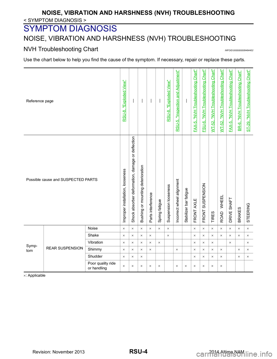
NVH Troubleshooting ChartINFOID:0000000009464452
Use the chart below to help you find the cause of the sy mptom. If necessary, repair or replace these parts.
×: ApplicableReference page
RSU-8, "Exploded View"
—
—
—
—
RSU-8, "Exploded View"
RSU-5, "Inspection and Adjustment"
—
FAX-5, "NVH Troubleshooting Chart"
FSU-6, "NVH Troubleshooting Chart"WT-52, "NVH Troubleshooting Chart"WT-52, "NVH Troubleshooting Chart"FAX-5, "NVH Troubleshooting Chart"BR-6, "NVH Troubleshooting Chart"ST-29, "NVH Troubleshooting Chart"
Possible cause and SUSPECTED PARTS
Improper installation, looseness
Shock absorber deformation, damage or deflection
Bushing or mounting deterioration
Parts interference
Spring fatigue
Suspension looseness
Incorrect wheel alignment
Stabilizer bar fatigue
FRONT AXLE
FRONT SUSPENSION
TIRES
ROAD WHEEL
DRIVE SHAFT
BRAKES
STEERING
Symp-
tom REAR SUSPENSION Noise
×××××× ×××××××
Shake ×××× × ×××××××
Vibration ××××× ××× × ×
Shimmy ×××× × ×××× ××
Shudder ××× ×××× ××
Poor quality ride
or handling ××××× ××××××
Revision: November 20132014 Altima NAM
Page 3723 of 4801
RSU-6
< PERIODIC MAINTENANCE >
REAR SUSPENSION ASSEMBLY
• Check the wheelarch height in the unladen condition. Refer to RSU-17, "Wheelarch Height (Unladen*1)".
GENERAL INFORMATION AND RECOMMENDATIONS
1. A Four-Wheel Thrust Alignment should be performed.
• This type of alignment is recommended for any NISSAN vehicle.
• The four-wheel “thrust” process helps ensure that the vehicle is properly aligned and the steering wheel
is centered.
• The alignment machine itself should be ca pable of accepting any NISSAN vehicle.
• The alignment machine should be checked to ensure that it is level.
2. Make sure the alignment machine is properly calibrated. • Your alignment machine should be regularly calibrated in order to give correct information.
• Check with the manufacturer of your specific al ignment machine for their recommended Service/Cali-
bration Schedule.
THE ALIGNMENT PROCESS
IMPORTANT: Use only the alignment specifications listed in this Service Manual. Refer to RSU-17,
"Wheelarch Height (Unladen*1)".
1. When displaying the alignment settings, many alignm ent machines use “indicators”: (Green/red, plus or
minus, Go/No Go). Do NOT use these indicators.
• The alignment specifications programmed into your alignment machine that operate these indicators
may not be correct.
• This may result in an ERROR.
2. Most camera-type alignment machines are equipped with both "Rolling Compensation" method and optional "Jacking Compensation" method to "com pensate" the alignment targets or head units.
"Rolling Compensation" is the preferred method.
• If using the "Rolling Compensation" method, after installing the alignment targets or head units, push or pull on the rear wheel to move the vehicle. Do not push or pull the vehicle body.
• If using the "Jacking Compensation" method, after in stalling the alignment targets or head units, raise
the vehicle and rotate the wheels 1/2 turn both ways.
NOTE:
Do not use the "Rolling Compensation" method if you are using sensor-type alignment equipment.
• Follow all instructions for the alignment machine you are using for more information.
CAMBER and TOE
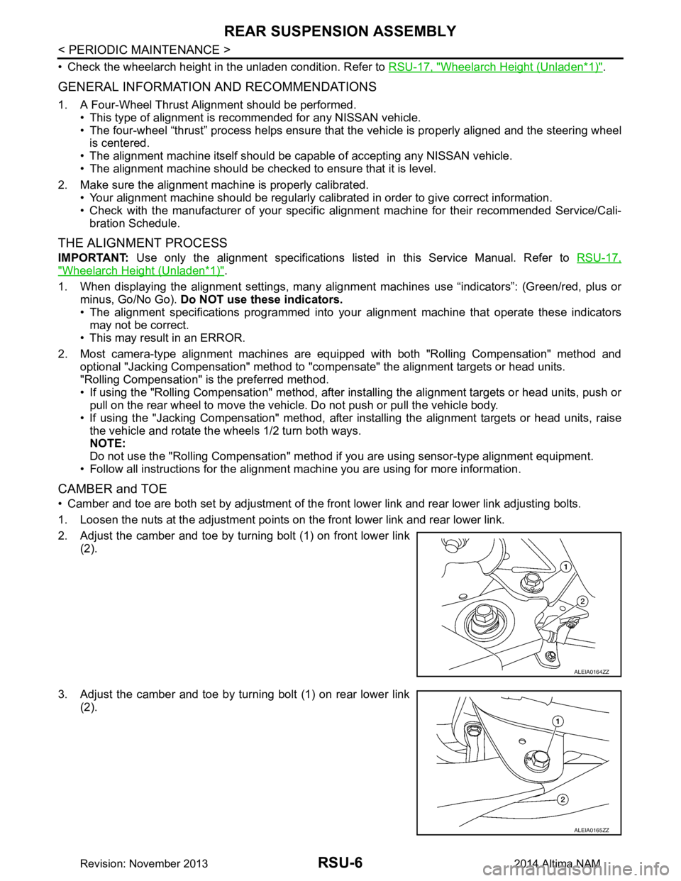
• Camber and toe are both set by adjustment of the fr ont lower link and rear lower link adjusting bolts.
1. Loosen the nuts at the adjustment points on the front lower link and rear lower link.
2. Adjust the camber and toe by turning bolt (1) on front lower link (2).
3. Adjust the camber and toe by turning bolt (1) on rear lower link (2).
ALEIA0164ZZ
ALEIA0165ZZ
Revision: November 20132014 Altima NAM
Page 3728 of 4801
REAR SUSPENSION ASSEMBLYRSU-11
< UNIT REMOVAL AND INSTALLATION >
C
D
F
G H
I
J
K L
M A
B
RSU
N
O P
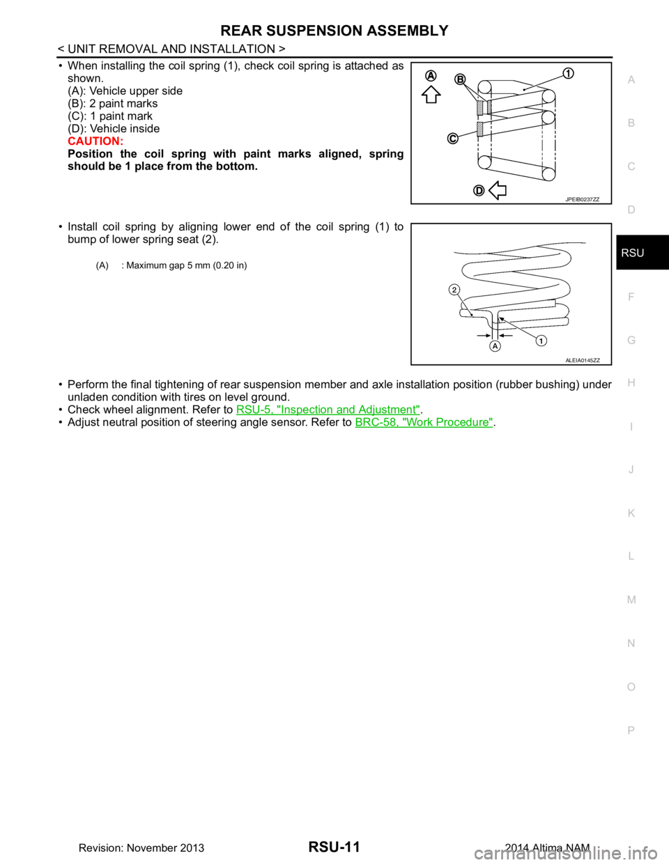
• When installing the coil spring (1), check coil spring is attached as shown.
(A): Vehicle upper side
(B): 2 paint marks
(C): 1 paint mark
(D): Vehicle inside
CAUTION:
Position the coil spring with paint marks aligned, spring
should be 1 place from the bottom.
• Install coil spring by aligning lower end of the coil spring (1) to bump of lower spring seat (2).
• Perform the final tightening of rear suspension me mber and axle installation position (rubber bushing) under
unladen condition with tires on level ground.
• Check wheel alignment. Refer to RSU-5, "Inspection and Adjustment"
.
• Adjust neutral position of steering angle sensor. Refer to BRC-58, "Work Procedure"
.
JPEIB0237ZZ
(A) : Maximum gap 5 mm (0.20 in)
ALEIA0145ZZ
Revision: November 20132014 Altima NAM