2014 NISSAN TEANA Pressure
[x] Cancel search: PressurePage 3203 of 4801
ENGINE MAINTENANCE (QR25DE)MA-19
< PERIODIC MAINTENANCE >
C
D E
F
G H
I
J
K L
M B
MA
N
O A
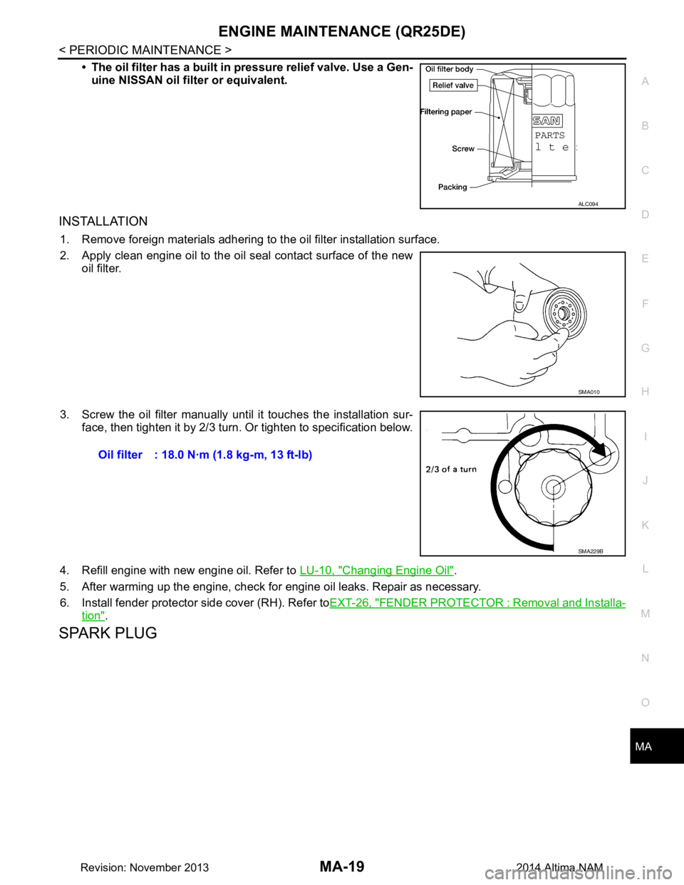
• The oil filter has a built in pressure relief valve. Use a Gen-
uine NISSAN oil filter or equivalent.
INSTALLATION
1. Remove foreign materials adhering to the oil filter installation surface.
2. Apply clean engine oil to the oil seal contact surface of the new oil filter.
3. Screw the oil filter manually unt il it touches the installation sur-
face, then tighten it by 2/3 turn. Or tighten to specification below.
4. Refill engine with new engine oil. Refer to LU-10, "Changing Engine Oil"
.
5. After warming up the engine, check for engine oil leaks. Repair as necessary.
6. Install fender protector side cover (RH). Refer to EXT-26, "FENDER PROTECTOR : Removal and Installa-
tion".
SPARK PLUG
ALC094
SMA010
Oil filter : 18.0 N·m (1.8 kg-m, 13 ft-lb)
SMA229B
Revision: November 20132014 Altima NAM
Page 3205 of 4801
ENGINE MAINTENANCE (QR25DE)MA-21
< PERIODIC MAINTENANCE >
C
D E
F
G H
I
J
K L
M B
MA
N
O A
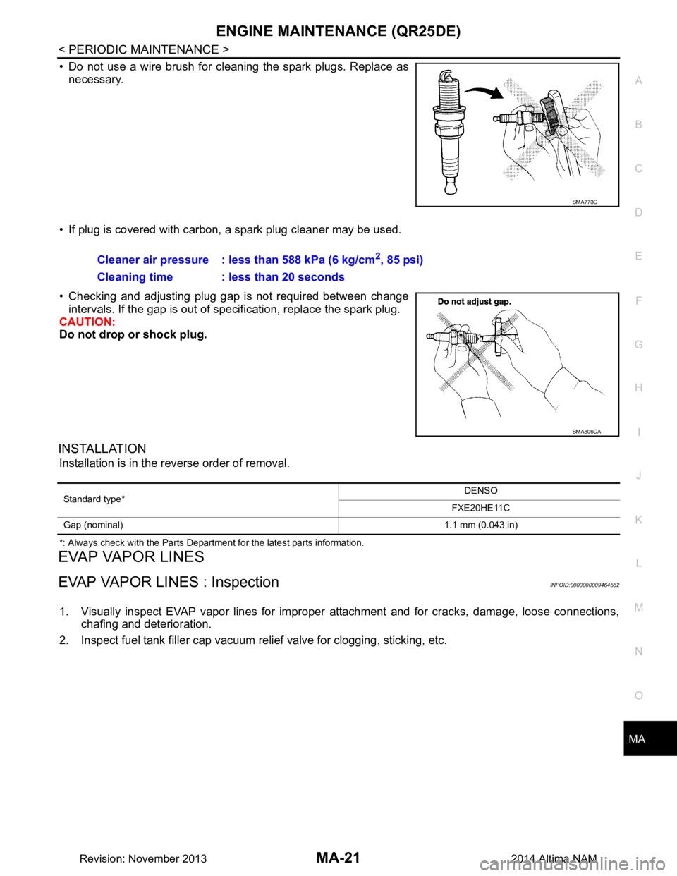
• Do not use a wire brush for cleaning the spark plugs. Replace as
necessary.
• If plug is covered with carbon, a spark plug cleaner may be used.
• Checking and adjusting plug gap is not required between change intervals. If the gap is out of s pecification, replace the spark plug.
CAUTION:
Do not drop or shock plug.
INSTALLATION
Installation is in the reverse order of removal.
*: Always check with the Parts Department for the latest parts information.
EVAP VAPOR LINES
EVAP VAPOR LINES : InspectionINFOID:0000000009464552
1. Visually inspect EVAP vapor lines for improper attachment and for cracks, damage, loose connections,
chafing and deterioration.
2. Inspect fuel tank filler cap vacuum relief valve for clogging, sticking, etc.
SMA773C
Cleaner air pressure : less than 588 kPa (6 kg/cm2, 85 psi)
Cleaning time : less than 20 seconds
SMA806CA
Standard type* DENSO
FXE20HE11C
Gap (nominal) 1.1 mm (0.043 in)
Revision: November 20132014 Altima NAM
Page 3207 of 4801
ENGINE MAINTENANCE (VQ35DE)MA-23
< PERIODIC MAINTENANCE >
C
D E
F
G H
I
J
K L
M B
MA
N
O A
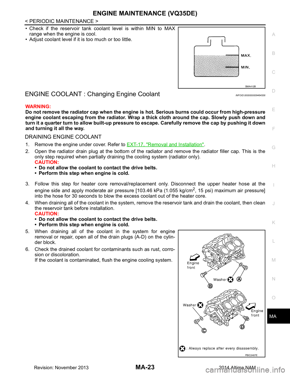
• Check if the reservoir tank coolant level is within MIN to MAX
range when the engine is cool.
• Adjust coolant level if it is too much or too little.
ENGINE COOLANT : Chang ing Engine CoolantINFOID:0000000009464556
WARNING:
Do not remove the radiator cap when the engine is hot. Serious burns could occur from high-pressure
engine coolant escaping from the radiator. Wrap a thick cloth around the cap. Slowly push down and
turn it a quarter turn to allow built-up pressure to escape. Carefully remove the cap by pushing it down
and turning it all the way.
DRAINING ENGINE COOLANT
1. Remove the engine under cover. Refer to EXT-17, "Removal and Installation".
2. Open the radiator drain plug at the bottom of the radiat or and remove the radiator filler cap. This is the
only step required when partially draining the cooling system (radiator only).
CAUTION:
• Do not allow the coolant to contact the drive belts.
• Perform this step when engine is cold.
3. Follow this step for heater core removal/repl acement only. Disconnect the upper heater hose at the
engine side and apply moderate air pressure [103.46 kPa (1.055 kg/cm
2, 15 psi) maximum air pressure]
into the hose for 30 seconds to blow the excess coolant out of the heater core.
4. When draining all of the coolant in the system, remo ve the reservoir tank and drain the coolant, then clean
the reservoir tank before installation.
CAUTION:
• Do not allow the coolant to contact the drive belts.
• Perform this step when engine is cold.
5. When draining all of the coolant in the system for engine removal or repair, open all of the drain plugs (A-D) on the cylin-
der block.
6. Check the drained coolant for contaminants such as rust, corro- sion or discoloration.
If the coolant is contaminated, flush the engine cooling system.
SMA412B
PBIC2487E
Revision: November 20132014 Altima NAM
Page 3208 of 4801
MA-24
< PERIODIC MAINTENANCE >
ENGINE MAINTENANCE (VQ35DE)
REFILLING ENGINE COOLANT
1. Install the radiator drain plug. If the cooling system was drained completely, install the reservoir tank and
the cylinder block drain plugs.
• The radiator must be complete ly empty of coolant and water.
• Apply sealant to the threads of the cylinder block drain plug. Use Genuine High Performance
Thread Sealant or equivalent. Refer to GI-21, "Recommended Chemical Products and Sealants"
.
CAUTION:
Do not reuse copp er sealing washers.
2. If disconnected, reattach the upper radiator hose at the engine side.
3. Set the vehicle heater controls to the full HOT and heat er ON position. Turn the vehicle ignition ON with
the engine OFF as necessary to activate the heater mode.
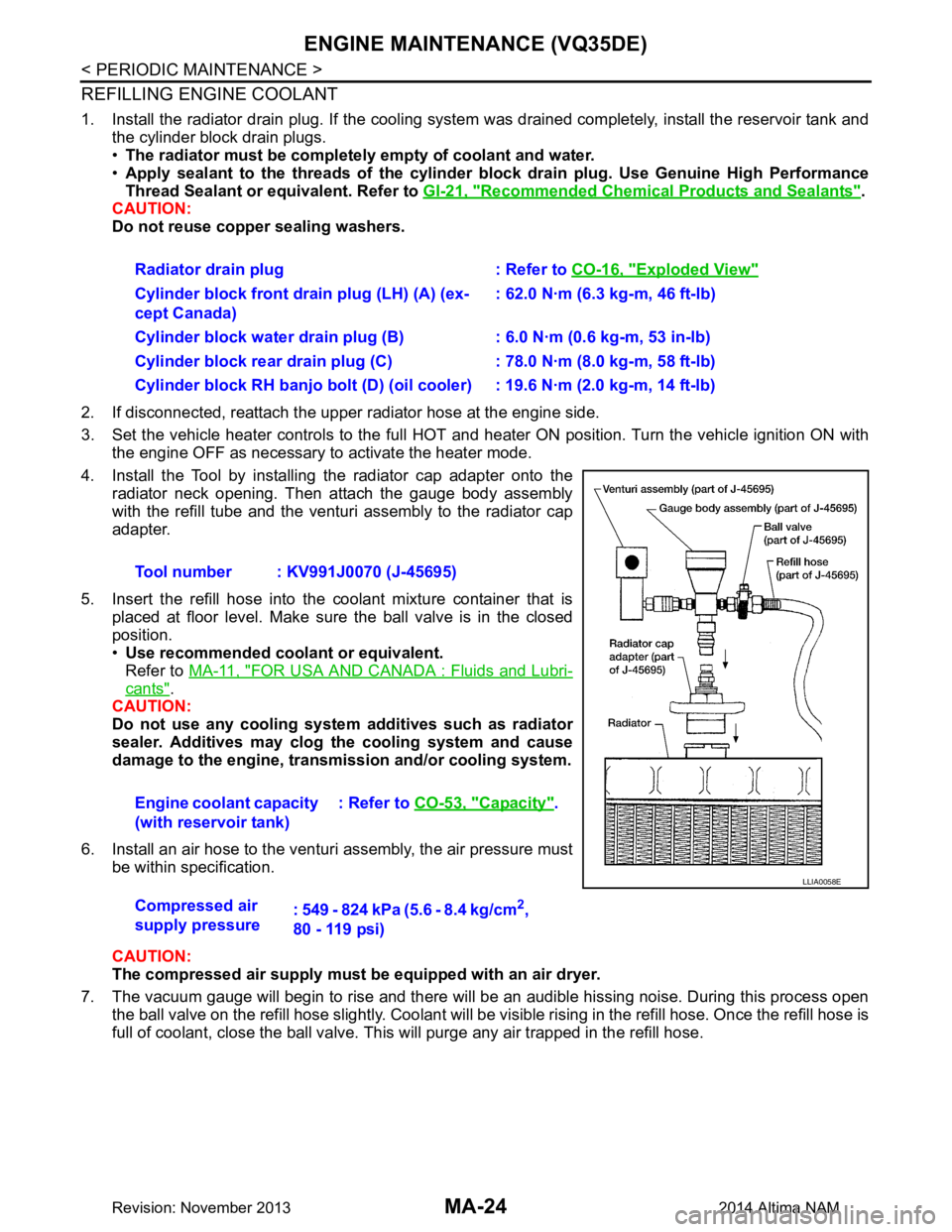
4. Install the Tool by installing the radiator cap adapter onto the radiator neck opening. Then attach the gauge body assembly
with the refill tube and the venturi assembly to the radiator cap
adapter.
5. Insert the refill hose into the coolant mixture container that is placed at floor level. Make sure the ball valve is in the closed
position.
• Use recommended coolant or equivalent.
Refer to MA-11, "FOR USA AND CANADA : Fluids and Lubri-
cants".
CAUTION:
Do not use any cooling system additives such as radiator
sealer. Additives may clog th e cooling system and cause
damage to the engine, transm ission and/or cooling system.
6. Install an air hose to the venturi assembly, the air pressure must be within specification.
CAUTION:
The compressed air supply must be equipped with an air dryer.
7. The vacuum gauge will begin to rise and there will be an audible hissing noise. During this process open the ball valve on the refill hose slightly. Coolant will be vi sible rising in the refill hose. Once the refill hose is
full of coolant, close the ball valve. This will purge any air trapped in the refill hose. Radiator drain plug : Refer to
CO-16, "Exploded View"
Cylinder block front drain plug (LH) (A) (ex-
cept Canada) : 62.0 N·m (6.3 kg-m, 46 ft-lb)
Cylinder block water drain plug (B) : 6.0 N·m (0.6 kg-m, 53 in-lb)
Cylinder block rear drain plug (C) : 78.0 N·m (8.0 kg-m, 58 ft-lb)
Cylinder block RH banjo bolt (D) (oil cooler) : 19.6 N·m (2.0 kg-m, 14 ft-lb)
Tool number : KV991J0070 (J-45695)
Engine coolant capacity
(with reservoir tank) : Refer to
CO-53, "Capacity"
.
Compressed air
supply pressure : 549 - 824 kPa (5.6 - 8.4 kg/cm
2,
80 - 119 psi)
LLIA0058E
Revision: November 20132014 Altima NAM
Page 3212 of 4801
MA-28
< PERIODIC MAINTENANCE >
ENGINE MAINTENANCE (VQ35DE)
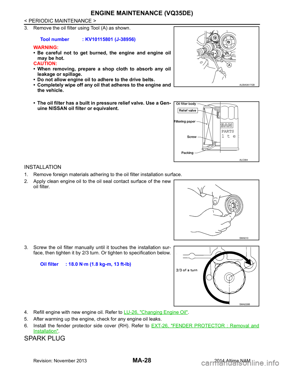
3. Remove the oil filter using Tool (A) as shown.WARNING:
• Be careful not to get burned, the engine and engine oil
may be hot.
CAUTION:
• When removing, prepare a shop cloth to absorb any oil
leakage or spillage.
• Do not allow engine oil to adhere to the drive belts.
• Completely wipe off any oil that adheres to the engine and
the vehicle.
• The oil filter has a built in pressure relief valve. Use a Gen-
uine NISSAN oil filter or equivalent.
INSTALLATION
1. Remove foreign materials adhering to the oil filter installation surface.
2. Apply clean engine oil to the oil seal contact surface of the new oil filter.
3. Screw the oil filter manually until it touches the installation sur- face, then tighten it by 2/3 turn. Or tighten to specification below.
4. Refill engine with new engine oil. Refer to LU-26, "Changing Engine Oil"
.
5. After warming up the engine, check for any engine oil leaks.
6. Install the fender protector side cover (RH). Refer to EXT-26, "FENDER PROTECTOR : Removal and
Installation".
SPARK PLUG
Tool number : KV10115801 (J-38956)
ALBIA0617GB
ALC094
SMA010
Oil filter : 18.0 N·m (1.8 kg-m, 13 ft-lb)
SMA229B
Revision: November 20132014 Altima NAM
Page 3214 of 4801
MA-30
< PERIODIC MAINTENANCE >
ENGINE MAINTENANCE (VQ35DE)
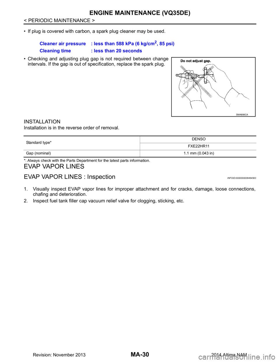
• If plug is covered with carbon, a spark plug cleaner may be used.
• Checking and adjusting plug gap is not required between change intervals. If the gap is out of s pecification, replace the spark plug.
INSTALLATION
Installation is in the reverse order of removal.
*: Always check with the Parts Department for the latest parts information.
EVAP VAPOR LINES
EVAP VAPOR LINES : InspectionINFOID:0000000009464563
1. Visually inspect EVAP vapor lines for improper attachment and for cracks, damage, loose connections,
chafing and deterioration.
2. Inspect fuel tank filler cap vacuum relief valve for clogging, sticking, etc. Cleaner air pressure : less than 588 kPa (6 kg/cm
2, 85 psi)
Cleaning time : less than 20 seconds
SMA806CA
Standard type* DENSO
FXE22HR11
Gap (nominal) 1.1 mm (0.043 in)
Revision: November 20132014 Altima NAM
Page 3257 of 4801

MWI-2
Wiring Diagram .......................................................30
METER ...............................................................32
Wiring Diagram .................................................... ...32
BASIC INSPECTION ...................................51
DIAGNOSIS AND REPAIR WORKFLOW ...... ...51
Work flow ............................................................. ...51
DTC/CIRCUIT DIAGNOSIS ...................... ...53
U1000 CAN COMM CIRCUIT ......................... ...53
DTC Logic ............................................................ ...53
Diagnosis Procedure .............................................53
U1010 CONTROL UNIT (CAN) .........................54
Description ........................................................... ...54
DTC Logic ...............................................................54
Diagnosis Procedure ..............................................54
B2205 VEHICLE SPEED ...................................55
Description ........................................................... ...55
DTC Logic ...............................................................55
Diagnosis Procedure .............................................55
B2267 ENGINE SPEED .....................................56
Description ........................................................... ...56
DTC Logic ...............................................................56
Diagnosis Procedure ..............................................56
B2268 WATER TEMP ........................................57
Description ........................................................... ...57
DTC Logic ...............................................................57
Diagnosis Procedure ..............................................57
POWER SUPPLY AND GROUND CIRCUIT .....58
COMBINATION METER ........................................ ...58
COMBINATION METER : Diagnosis Procedure ....58
BCM (BODY CONTROL MODULE) ...................... ...58
BCM (BODY CONTROL MODULE) : Diagnosis
Procedure ............................................................ ...
58
IPDM E/R (INTELLIGENT POWER DISTRIBU-
TION MODULE ENGINE ROOM) .......................... ...
59
IPDM E/R (INTELLIGENT POWER DISTRIBU-
TION MODULE ENGINE ROOM) : Diagnosis Pro-
cedure .................................................................. ...
59
FUEL LEVEL SENSOR SIGNAL CIRCUIT .......61
Description ........................................................... ...61
Component Function Check ...................................61
Diagnosis Procedure .............................................61
Component Inspection ............................................62
PARKING BRAKE SWITCH SIGNAL CIR-
CUIT ................................................................ ...
63
Description ........................................................... ...63
Component Function Check ...................................63
Diagnosis Procedure ..............................................63
Component Inspection ......................................... ...63
WASHER FLUID LEVEL SWITCH CIRCUIT ....64
Description ........................................................... ...64
Diagnosis Procedure ...............................................64
Component Inspection ............................................64
AMBIENT SENSOR SIGNAL CIRCUIT ............66
Description ........................................................... ...66
Component Function Check ...................................66
Diagnosis Procedure ...............................................66
Component Inspection ............................................67
METER CONTROL SWITCH SIGNAL CIR-
CUIT ................................................................ ...
68
Diagnosis Procedure ............................................ ...68
Component Inspection ............................................69
STEERING SWITCH ..........................................70
Description ........................................................... ...70
Diagnosis Procedure ...............................................70
Component Inspection ............................................70
SYMPTOM DIAGNOSIS ............................72
THE FUEL GAUGE INDICATOR DOES NOT
OPERATE ....................................................... ...
72
Description ........................................................... ...72
Diagnosis Procedure ...............................................72
THE METER CONTROL SWITCH IS INOPER-
ATIVE .............................................................. ...
73
Description ........................................................... ...73
Diagnosis Procedure ...............................................73
THE OIL PRESSURE WARNING CONTIN-
UES DISPLAYING, OR DOES NOT DISPLAY ...
74
Description ........................................................... ...74
Diagnosis Procedure ...............................................74
THE PARKING BRAKE RELEASE WARNING
CONTINUES DISPLAYING, OR DOES NOT
DISPLAY ......................................................... ...
75
Description ........................................................... ...75
Diagnosis Procedure ...............................................75
THE LOW WASHER FLUID WARNING CON-
TINUES DISPLAYING, or DOES NOT DIS-
PLAY ............................................................... ...
76
Description ........................................................... ...76
Diagnosis Procedure ...............................................76
THE DOOR OPEN WARNING CONTINUES
DISPLAYING, OR DOES NOT DISPLAY ...... ...
77
Description ........................................................... ...77
Diagnosis Procedure ...............................................77
THE TRUNK OPEN WARNING CONTINUES
DISPLAYING, OR DOES NOT DISPLAY ...... ...
78
Description ........................................................... ...78
Diagnosis Procedure ...............................................78
Revision: November 20132014 Altima NAMRevision: November 20132014 Altima NAM
Page 3262 of 4801
MWI
COMPONENT PARTSMWI-7
< SYSTEM DESCRIPTION >
C
D E
F
G H
I
J
K L
M B
A
O P
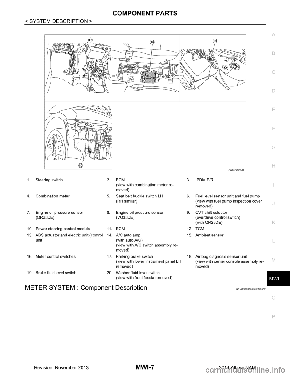
METER SYSTEM : Component DescriptionINFOID:0000000009461670
1. Steering switch 2. BCM (view with combination meter re-
moved) 3. IPDM E/R
4. Combination meter 5. Seat belt buckle switch LH (RH similar) 6. Fuel level sensor unit and fuel pump
(view with fuel pump inspection cover
removed)
7. Engine oil pressure sensor (QR25DE) 8. Engine oil pressure sensor
(VQ35DE) 9. CVT shift selector
(overdrive control switch)
(with QR25DE)
10. Power steering control module 11. ECM 12. TCM
13. ABS actuator and electric unit (control unit) 14. A/C auto amp
(with auto A/C)
(view with A/C swit ch assembly re-
moved) 15. Ambient sensor
16. Meter control switches 17. Parking brake switch (view with lower instrument panel LH
removed) 18. Air bag diagnosis sensor unit
(view with center console assembly re-
moved)
19. Brake fluid level switch 20. Washer fluid level switch (view with front fascia removed)
AWNIA2641ZZ
Revision: November 20132014 Altima NAMRevision: November 20132014 Altima NAM