2014 NISSAN TEANA Pressure
[x] Cancel search: PressurePage 3181 of 4801
![NISSAN TEANA 2014 Service Manual
OIL PUMPLU-31
< REMOVAL AND INSTALLATION > [VQ35DE]
C
D E
F
G H
I
J
K L
M A
LU
NP
O
1. Visually inspect components for wear and damage.
2. Check oil pressure regulator valve sliding surface and val NISSAN TEANA 2014 Service Manual
OIL PUMPLU-31
< REMOVAL AND INSTALLATION > [VQ35DE]
C
D E
F
G H
I
J
K L
M A
LU
NP
O
1. Visually inspect components for wear and damage.
2. Check oil pressure regulator valve sliding surface and val](/manual-img/5/57390/w960_57390-3180.png)
OIL PUMPLU-31
< REMOVAL AND INSTALLATION > [VQ35DE]
C
D E
F
G H
I
J
K L
M A
LU
NP
O
1. Visually inspect components for wear and damage.
2. Check oil pressure regulator valve sliding surface and valve spring.
3. Coat regulator valve with engine oil. Check that it falls smoothly into the valve hole by its own weight.
If damaged, replace oil pump assembly.
Regulator Valve Clearance
(Clearance 6) = D (Valve hole diameter) – E (Outer diameter of
valve)
If it exceeds the standard, replace the oil pump assembly.
CAUTION:
• Coat regulator valve with engine oil.
• Check that it falls smoothly into the valve hole by its own
weight.
SLC251B
Standard : LU-34, "Regulator Valve"
SLC935AA
Revision: November 20132014 Altima NAM
Page 3183 of 4801
![NISSAN TEANA 2014 Service Manual
OIL COOLERLU-33
< REMOVAL AND INSTALLATION > [VQ35DE]
C
D E
F
G H
I
J
K L
M A
LU
NP
O
When removing components such as hoses, tubes/lines, etc.
, cap or plug openings to prevent fluid from spill-
in NISSAN TEANA 2014 Service Manual
OIL COOLERLU-33
< REMOVAL AND INSTALLATION > [VQ35DE]
C
D E
F
G H
I
J
K L
M A
LU
NP
O
When removing components such as hoses, tubes/lines, etc.
, cap or plug openings to prevent fluid from spill-
in](/manual-img/5/57390/w960_57390-3182.png)
OIL COOLERLU-33
< REMOVAL AND INSTALLATION > [VQ35DE]
C
D E
F
G H
I
J
K L
M A
LU
NP
O
When removing components such as hoses, tubes/lines, etc.
, cap or plug openings to prevent fluid from spill-
ing.
REMOVAL
1. Remove the engine under cover. Refer to EXT-17, "Removal and Installation".
2. Remove the RH wheel and tire. Refer to WT-53, "Inspection"
.
3. Remove the front fender protector side cover RH. Refer to EXT-26, "FENDER PROTECTOR : Exploded
View".
4. Drain engine coolant. Refer to CO-36, "Changing Engine Coolant"
.
CAUTION:
Do not spill coolant on the drive belt.
5. Disconnect water hoses from oil cooler.
6. Remove the oil filter. Refer to LU-27, "Removal and Installation"
.
7. Remove oil cooler.
8. Remove core support cover. Refer to DLK-179, "Removal and Installation"
.
9. Remove front air duct. Refer to EM-84, "Removal and Installation"
.
10. Remove reservoir tank. Refer to CO-40, "Exploded View"
.
INSPECTION AFTER REMOVAL
1. Check oil cooler for cracks.
2. Check oil cooler for clogging by blowing through coolant inlet. If necessary, replace oil cooler.
Oil Pressure Relief Valve
Inspect oil pressure relief valve for movement, cracks and breaks by pushing the ball. If replacement is neces-
sary, remove valve by prying it out with a suitable tool. Install a new valve in place by tapping it.
INSTALLATION
Installation is in the reverse order of removal.
CAUTION:
• Do not reuse O-ring.
• Do not reuse copper gasket.
• When installing the oil cooler, align the oil cooler slot with the stopper of the oil pan.
INSPECTION AFTER INSTALLATION
1. Check the engine oil level and the engine coolant level and add engine oil and engine coolant. Refer to LU-9, "Inspection"
and CO-11, "System Inspection".
2. Start the engine, and check that there is no leakage of engine oil or engine coolant.
3. Stop the engine and wait for 10 minutes.
4. Check the engine oil level and the engine coolant level again. Refer to LU-9, "Inspection"
and CO-11,
"System Inspection".
Revision: November 20132014 Altima NAM
Page 3184 of 4801
![NISSAN TEANA 2014 Service Manual
LU-34
< SERVICE DATA AND SPECIFICATIONS (SDS) [VQ35DE]
SERVICE DATA AND SPECIFICATIONS (SDS)
SERVICE DATA AND SPECIFICATIONS (SDS)
SERVICE DATA AND SPECIFICATIONS (SDS)
Oil PressureINFOID:00000000094 NISSAN TEANA 2014 Service Manual
LU-34
< SERVICE DATA AND SPECIFICATIONS (SDS) [VQ35DE]
SERVICE DATA AND SPECIFICATIONS (SDS)
SERVICE DATA AND SPECIFICATIONS (SDS)
SERVICE DATA AND SPECIFICATIONS (SDS)
Oil PressureINFOID:00000000094](/manual-img/5/57390/w960_57390-3183.png)
LU-34
< SERVICE DATA AND SPECIFICATIONS (SDS) [VQ35DE]
SERVICE DATA AND SPECIFICATIONS (SDS)
SERVICE DATA AND SPECIFICATIONS (SDS)
SERVICE DATA AND SPECIFICATIONS (SDS)
Oil PressureINFOID:0000000009461057
Unit: kPa (kg/cm2, psi)
*: Engine oil temperature at 80
°C (176 °F)
Oil PumpINFOID:0000000009461058
Unit: mm (in)
Regulator ValveINFOID:0000000009461059
Unit: mm (in)
Oil CapacityINFOID:0000000009461060
Unit: (US qt, Imp qt)
Engine speed Approximate discharge oil pressure*
Idle speed 98 (1.0, 14)
2,000 rpm 294 (3.0, 43)
6,000 rpm 392 (4.0, 57)
Clearance between outer rotor and oil pump body 0.114 - 0.260 (0.0045 - 0.0102)
Tip clearance between inner rotor and outer rotor Below 0.180 (0.0071)
Side clearance between inner rotor and oil pump body 0.030 - 0.070 (0.0012 - 0.0028)
Side clearance between outer rotor and oil pump body 0.050 - 0.110 (0.0020 - 0.0043)
Clearance between inner rotor and oil pump body 0.045 - 0.091 (0.0018 - 0.0036)
Regulator valve to oil pump cover clearance 0.040 - 0.097 (0.0016 - 0.0038)
Drain and refill With oil filter change 4.8 (5-1/8, 4-1/4)
Without oil filter change 4.5 (4-3/4, 4)
Dry engine (engine overhaul) 5.3 (5-5/8, 4-5/8)
Revision: November 20132014 Altima NAM
Page 3189 of 4801
GENERAL MAINTENANCEMA-5
< PERIODIC MAINTENANCE >
C
D E
F
G H
I
J
K L
M B
MA
N
O A
PERIODIC MAINTENANCE
GENERAL MAINTENANCE
FOR USA AND CANADA
FOR USA AND CANADA : Explana
tion of General MaintenanceINFOID:0000000009464530
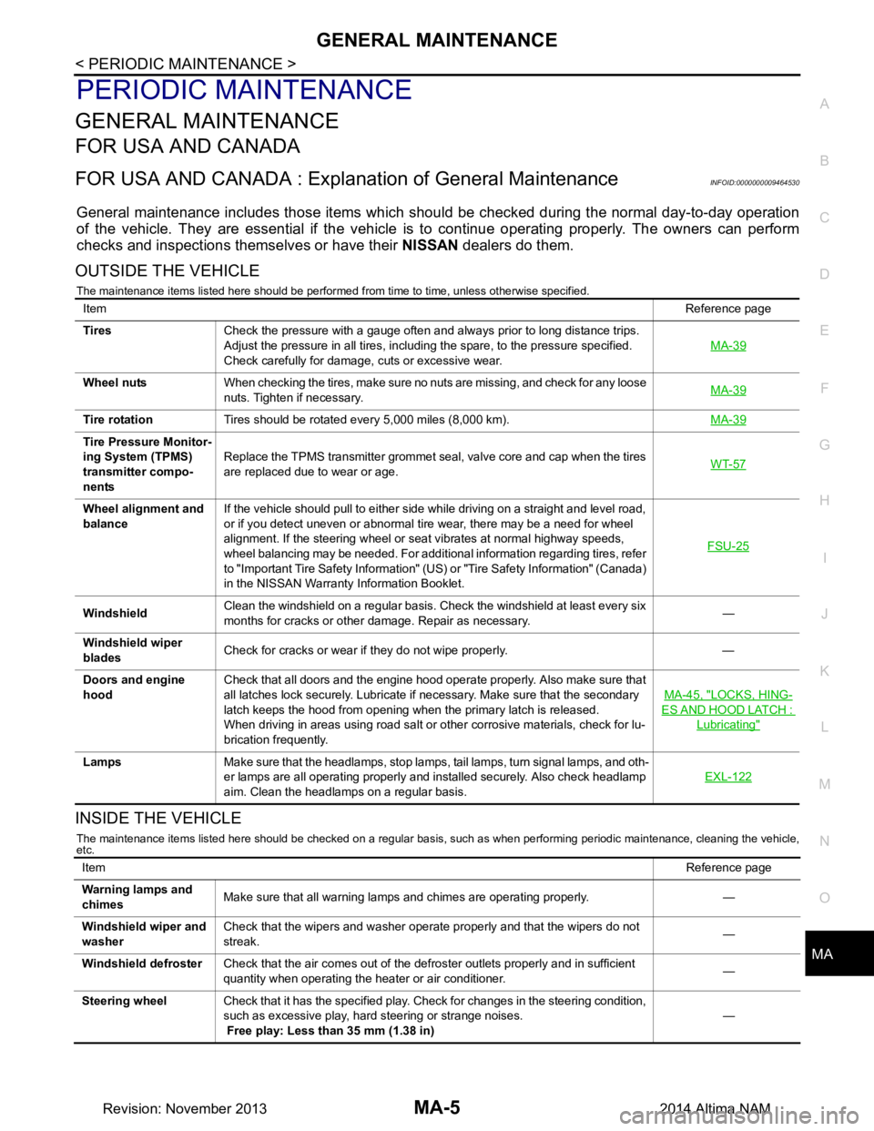
General maintenance includes those items which shoul d be checked during the normal day-to-day operation
of the vehicle. They are essential if the vehicle is to continue operating properly. The owners can perform
checks and inspections themselves or have their NISSAN dealers do them.
OUTSIDE THE VEHICLE
The maintenance items listed here should be performed from time to time, unless otherwise specified.
INSIDE THE VEHICLE
The maintenance items listed here should be checked on a regular basis, such as when performing periodic maintenance, cleaning the vehicle,
etc.
Item Reference page
Tires Check the pressure with a gauge often and always prior to long distance trips.
Adjust the pressure in all tires, including the spare, to the pressure specified.
Check carefully for damage, cuts or excessive wear. MA-39
Wheel nuts
When checking the tires, make sure no nuts are missing, and check for any loose
nuts. Tighten if necessary. MA-39
Tire rotation
Tires should be rotated every 5,000 miles (8,000 km). MA-39
Tire Pressure Monitor-
ing System (TPMS)
transmitter compo-
nents Replace the TPMS transmitter grommet seal, valve core and cap when the tires
are replaced due to wear or age. WT-57
Wheel alignment and
balance If the vehicle should pull to either side while driving on a straight and level road,
or if you detect uneven or abnormal tire wear, there may be a need for wheel
alignment. If the steering wheel or seat vibrates at normal highway speeds,
wheel balancing may be needed. For additional information regarding tires, refer
to "Important Tire Safety Information" (US) or "Tire Safety Information" (Canada)
in the NISSAN Warranty Information Booklet. FSU-25
Windshield
Clean the windshield on a regular basis. Check the windshield at least every six
months for cracks or other damage. Repair as necessary. —
Windshield wiper
blades Check for cracks or wear if they do not wipe properly. —
Doors and engine
hood Check that all doors and the engine hood operate properly. Also make sure that
all latches lock securely. Lubricate if necessary. Make sure that the secondary
latch keeps the hood from opening when the primary latch is released.
When driving in areas using road salt or other corrosive materials, check for lu-
brication frequently. MA-45, "LOCKS, HING-
ES AND HOOD LATCH :
Lubricating"
Lamps
Make sure that the headlamps, stop lamps, tail lamps, turn signal lamps, and oth-
er lamps are all operating properly and installed securely. Also check headlamp
aim. Clean the headlamps on a regular basis. EXL-122
Item
Reference page
Warning lamps and
chimes Make sure that all warning lamps and chimes are operating properly. —
Windshield wiper and
washer Check that the wipers and washer operate properly and that the wipers do not
streak. —
Windshield defroster Check that the air comes out of the defroster outlets properly and in sufficient
quantity when operating the heater or air conditioner. —
Steering wheel Check that it has the specified play. Check for changes in the steering condition,
such as excessive play, hard steering or strange noises.
Free play: Less than 35 mm (1.38 in) —
Revision: November 20132014 Altima NAM
Page 3196 of 4801
MA-12
< PERIODIC MAINTENANCE >
RECOMMENDED FLUIDS AND LUBRICANTS
FOR USA AND CANADA : Engi ne Coolant Mixture Ratio
INFOID:0000000009464538
The engine cooling system is filled at the factory with a pre-diluted mixture of 50% Genuine NISSAN Long Life
Antifreeze/Coolant (blue) and 50% water to provide year-round anti-freeze and coolant protection. The anti-
freeze solution contains rust and corrosion inhibitors. Additional engine cooling system additives are not nec-
essary.
WARNING:
• Do not remove the radiator or coolant reservoir cap wh en the engine is hot. Wait until the engine and
radiator cool down. Serious burns could be caused by high pressure fluid escaping from the radia-
tor.
• The radiator is equipped with a pressure type radiator cap. To prevent engine damage, use only a
genuine NISSAN radiator cap.
CAUTION:
• When adding or replacing coolant, be sure to use only Genuine NISSAN Long Life Antifreeze/Cool-
ant (blue) or equivalent. Genuine NISSAN Long Life Antifreeze/Coolant (blue) is pre-diluted to pro-
vide antifreeze protection to -34°F (-37°C). If additional freeze protection is needed due to weather
where you operate your vehicle, add Genuine NISS AN Long Life Antifreeze/Coolant (blue) concen-
trate following the directions on the container. If an equivalent coolant other than Genuine NISSAN
Long Life Antifreeze/Coolant (blue) is used, follow the coolant manufacturer’s instructions to main-
tain minimum antifreeze protection to -34°F (-37°C). The use of other types of coolant solutions other
than Genuine NISSAN Long Life Antifreeze/Coolant (blue) or equivalent may damage the engine
cooling system.
• Mixing any other type of coolant other than Genu ine NISSAN Long Life Antifreeze/Coolant (blue),
including Genuine NISSAN Long Life Antifreeze/Coolant (green), or the use of non-distilled water will
reduce the life expectancy of the factory-fill coolant.
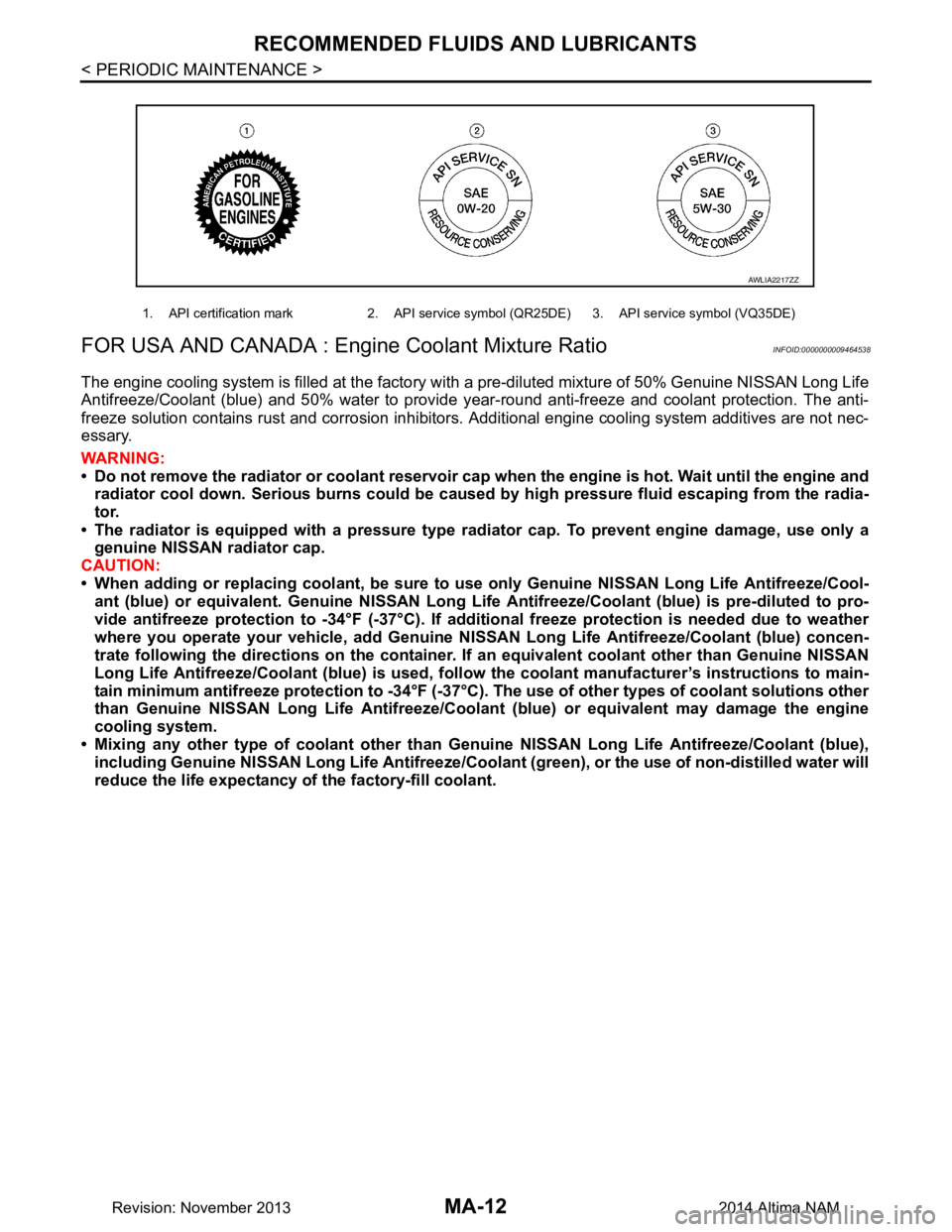
1. API certification mark 2. API service symbol (QR25DE) 3. API service symbol (VQ35DE)
AWLIA2217ZZ
Revision: November 20132014 Altima NAM
Page 3197 of 4801
ENGINE MAINTENANCE (QR25DE)MA-13
< PERIODIC MAINTENANCE >
C
D E
F
G H
I
J
K L
M B
MA
N
O A
ENGINE MAINTENANCE (QR25DE)
DRIVE BELTS
DRIVE BELTS : Checking Drive BeltsINFOID:0000000009464542
WARNING:
Inspect the drive belt only when the engine is stopped.
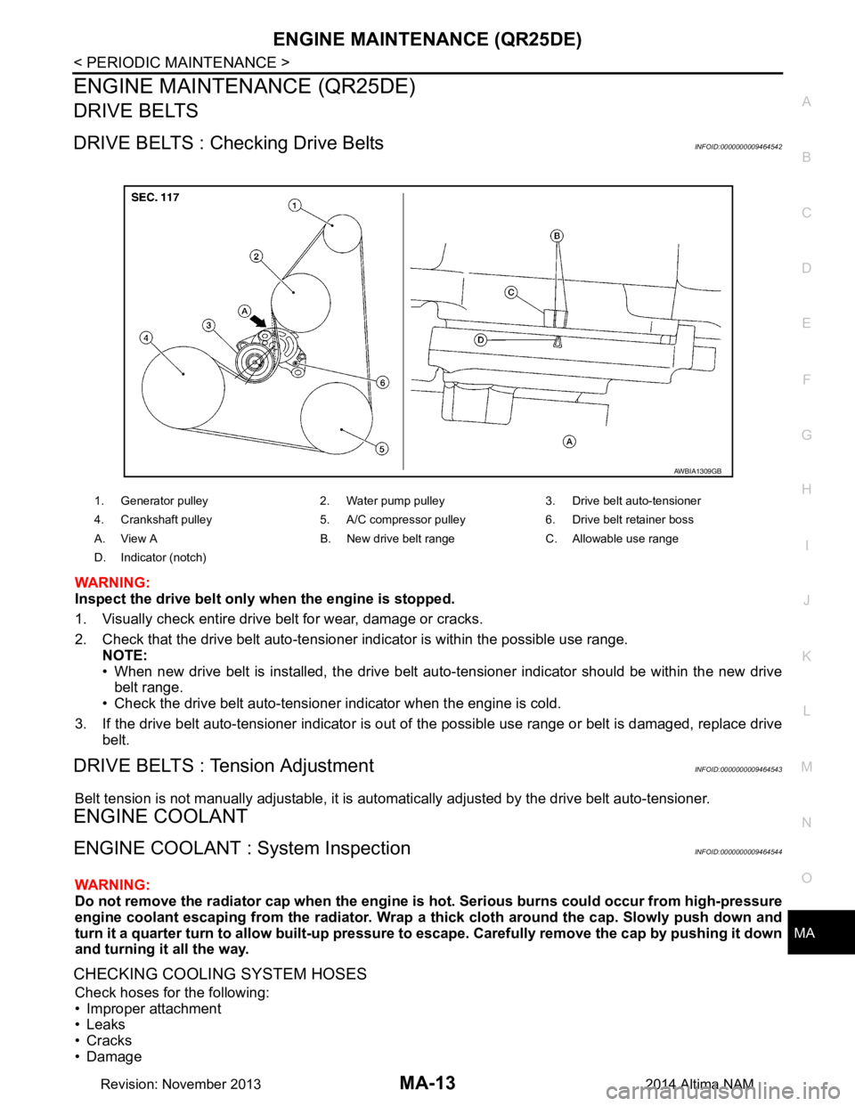
1. Visually check entire drive belt for wear, damage or cracks.
2. Check that the drive belt auto-tensioner indicator is within the possible use range.
NOTE:
• When new drive belt is installed, the drive belt aut o-tensioner indicator should be within the new drive
belt range.
• Check the drive belt auto-tensioner indicator when the engine is cold.
3. If the drive belt auto-tensioner indicator is out of the possible use range or belt is damaged, replace drive
belt.
DRIVE BELTS : Tension AdjustmentINFOID:0000000009464543
Belt tension is not manually adjustable, it is aut omatically adjusted by the drive belt auto-tensioner.
ENGINE COOLANT
ENGINE COOLANT : System InspectionINFOID:0000000009464544
WARNING:
Do not remove the radiator cap when the engine is hot. Serious burns could occur from high-pressure
engine coolant escaping from the radiator. Wrap a thick cloth around the cap. Slowly push down and
turn it a quarter turn to allow built-up pressure to escape. Carefully remove the cap by pushing it down
and turning it all the way.
CHECKING COOLING SYSTEM HOSES
Check hoses for the following:
• Improper attachment
• Leaks
•Cracks
• Damage
1. Generator pulley 2. Water pump pulley 3. Drive belt auto-tensioner
4. Crankshaft pulley 5. A/C compressor pulley 6. Drive belt retainer boss
A. View A B. New drive belt range C. Allowable use range
D. Indicator (notch)
AWBIA1309GB
Revision: November 20132014 Altima NAM
Page 3198 of 4801
MA-14
< PERIODIC MAINTENANCE >
ENGINE MAINTENANCE (QR25DE)
• Loose connections
• Chafing
• Deterioration
CHECKING RESERVOIR LEVEL
• Check if the reservoir tank coolant level is within MIN to MAX when the engine is cool.
• Adjust coolant level if it is too much or too little.
ENGINE COOLANT : Changing Engine CoolantINFOID:0000000009464545
WARNING:
• To avoid being scalded, do not change the coolant when the engine is hot.
• Wrap a thick cloth around cap and carefully remove the cap. First, turn the cap a quarter of a turn to
release built-up pressure. Then push down and turn the cap all the way to remove.
DRAINING ENGINE COOLANT
1. Remove the engine under cover. Refer to EXT-17, "Removal and Installation".
2. Open the radiator drain plug at the bottom of the radi ator and remove the radiator filler cap. This is the
only step required when partially draining the cooling system (radiator only).
CAUTION:
• Do not allow the coolant to contact the drive belt.
• Perform this step when engine is cold.
3. Follow this step for heater core removal/replac ement only. Disconnect the upper heater hose at the
engine side and apply moderate air pressure [103.46 kPa (1.055 kg/cm
2, 15 psi) maximum air pressure]
into the hose for 30 seconds to blow t he excess coolant out of the heater core.
4. When draining all of the coolant in the system, re move the reservoir tank and drain the coolant, then clean
the reservoir tank before installation.
CAUTION:
• Do not allow the coolant to contact the drive belt.
• Perform this step when engine is cold.
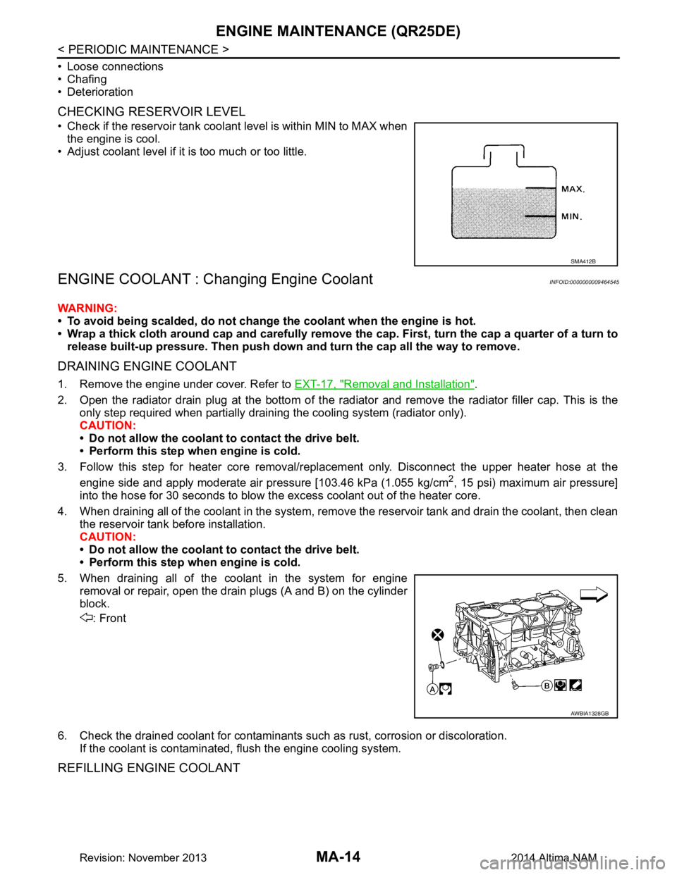
5. When draining all of the coolant in the system for engine removal or repair, open the drain plugs (A and B) on the cylinder
block.
: Front
6. Check the drained coolant for contaminants such as rust, corrosion or discoloration.
If the coolant is contaminated, flush the engine cooling system.
REFILLING ENGINE COOLANT
SMA412B
AWBIA1328GB
Revision: November 20132014 Altima NAM
Page 3199 of 4801
ENGINE MAINTENANCE (QR25DE)MA-15
< PERIODIC MAINTENANCE >
C
D E
F
G H
I
J
K L
M B
MA
N
O A
1. Install the radiator drain plug. Install the reservoir tank and cylin-
der block drain plug, if removed for a total system drain or for
engine removal or repair.
• The radiator must be completely empty of coolant and
water.
• Apply sealant to the threads of the cylinder block drain
plug. Use Genuine High Pe rformance Thread Sealant or
equivalent. Refer to GI-21, "Recommended Chemical
Products and Sealants".
: Front
CAUTION:
Do not reuse copper sealing washers.
2. If disconnected, reattach the upper radiator hose at the engine side.
3. Set the vehicle heater controls to the full HOT and heat er ON position. Turn the vehicle ignition ON with
the engine OFF as necessary to activate the heater mode.
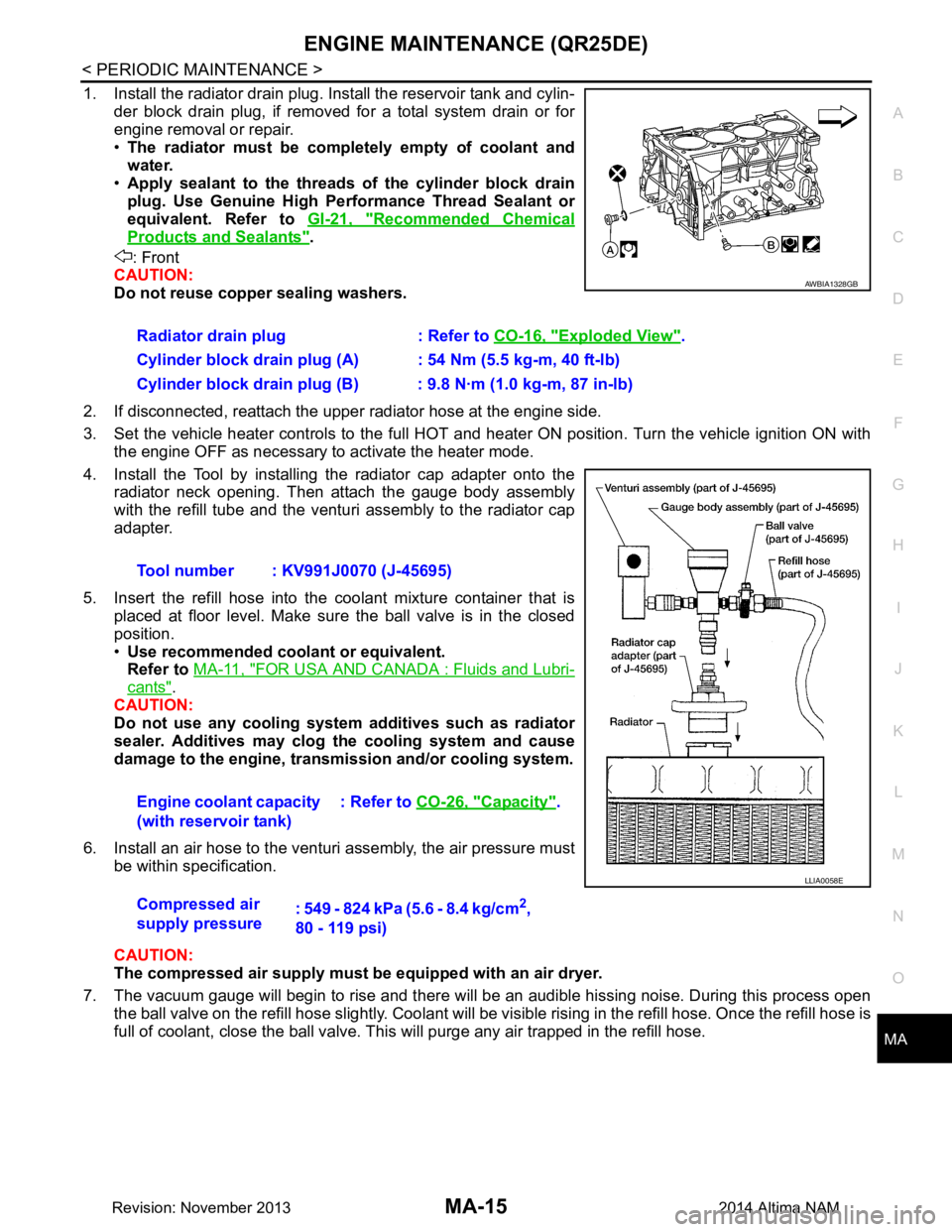
4. Install the Tool by installing the radiator cap adapter onto the radiator neck opening. Then attach the gauge body assembly
with the refill tube and the venturi assembly to the radiator cap
adapter.
5. Insert the refill hose into the coolant mixture container that is
placed at floor level. Make sure the ball valve is in the closed
position.
• Use recommended coolant or equivalent.
Refer to MA-11, "FOR USA AND CANADA : Fluids and Lubri-
cants".
CAUTION:
Do not use any cooling system additives such as radiator
sealer. Additives may clog th e cooling system and cause
damage to the engine, transmission and/or cooling system.
6. Install an air hose to the venturi assembly, the air pressure must be within specification.
CAUTION:
The compressed air supply must be equipped with an air dryer.
7. The vacuum gauge will begin to rise and there will be an audible hissing noise. During this process open the ball valve on the refill hose slightly. Coolant will be vi sible rising in the refill hose. Once the refill hose is
full of coolant, close the ball valve. Th is will purge any air trapped in the refill hose.
Radiator drain plug : Refer to
CO-16, "Exploded View"
.
Cylinder block drain plug (A) : 54 Nm (5.5 kg-m, 40 ft-lb)
Cylinder block drain plug (B) : 9.8 N·m (1.0 kg-m, 87 in-lb)
Tool number : KV991J0070 (J-45695)
Engine coolant capacity
(with reservoir tank) : Refer to
CO-26, "Capacity"
.
Compressed air
supply pressure : 549 - 824 kPa (5.6 - 8.4 kg/cm
2,
80 - 119 psi)
AWBIA1328GB
LLIA0058E
Revision: November 20132014 Altima NAM