2014 NISSAN TEANA Pressure
[x] Cancel search: PressurePage 3484 of 4801
PG-52
< DTC/CIRCUIT DIAGNOSIS >
HARNESS
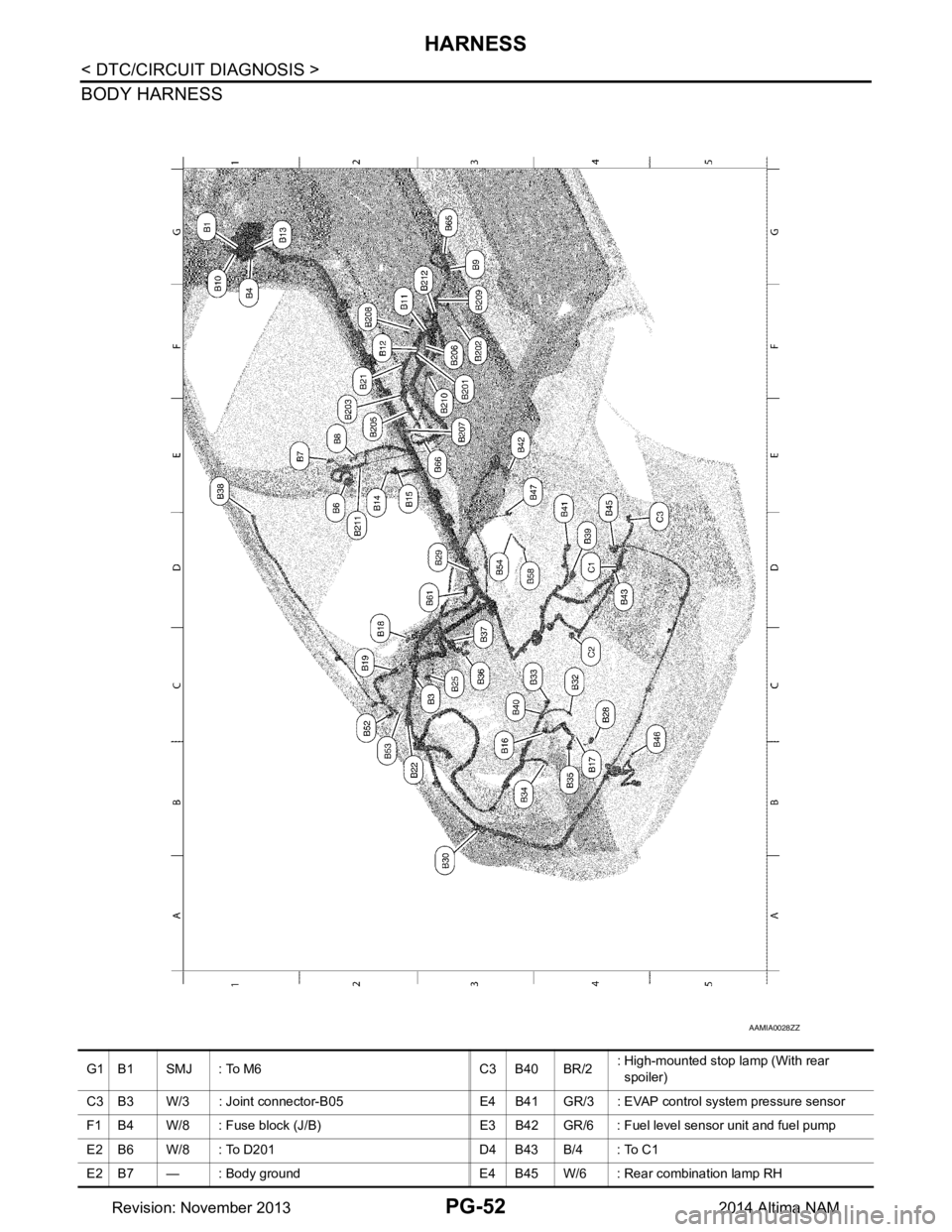
BODY HARNESS
AAMIA0028ZZ
G1 B1 SMJ : To M6 C3 B40 BR/2: High-mounted stop lamp (With rear
spoiler)
C3 B3 W/3 : Joint connector-B05 E4 B41 GR/3 : EVAP control system pressure sensor
F1 B4 W/8 : Fuse block (J/B) E3 B42 GR/6 : Fuel level sensor unit and fuel pump
E2 B6 W/8 : To D201 D4 B43 B/4 : To C1
E2 B7 — : Body ground E4 B45 W/6 : Rear combination lamp RH
Revision: November 20132014 Altima NAM
Page 3521 of 4801
![NISSAN TEANA 2014 Service Manual
PWC-14
< SYSTEM DESCRIPTION >[LH FRONT ONLY ANTI-PINCH]
DIAGNOSIS SYSTEM (BCM)
RETAINED PWR
RETAINED PWR : CONSULT Function (BCM - RETAINED PWR)INFOID:0000000009955264
CAUTION:
After disconnecting t NISSAN TEANA 2014 Service Manual
PWC-14
< SYSTEM DESCRIPTION >[LH FRONT ONLY ANTI-PINCH]
DIAGNOSIS SYSTEM (BCM)
RETAINED PWR
RETAINED PWR : CONSULT Function (BCM - RETAINED PWR)INFOID:0000000009955264
CAUTION:
After disconnecting t](/manual-img/5/57390/w960_57390-3520.png)
PWC-14
< SYSTEM DESCRIPTION >[LH FRONT ONLY ANTI-PINCH]
DIAGNOSIS SYSTEM (BCM)
RETAINED PWR
RETAINED PWR : CONSULT Function (BCM - RETAINED PWR)INFOID:0000000009955264
CAUTION:
After disconnecting the CONSULT vehicle interface (VI) from the data link connector, the ignition must
be cycled OFF → ON (for at least 5 seconds) → OFF. If this step is not performed, the BCM may not go
to ”sleep mode”, potentially causing a di scharged battery and a no-start condition.
DATA MONITOR
RAP system RETAINED PWR ×
Signal buffer system SIGNAL BUFFER ×
TPMS AIR PRESSURE MONITOR ××××
System Sub System
Direct Diagnostic Mode
Ecu Identification
Self Diagnostic Result
Data Monitor
Active Test
Work support
Configuration
CAN Diag Support Mntr
Monitor Item [Unit] Description
DOOR SW-DR [On/Off] Indicates condition of front door switch LH.
DOOR SW-AS [On/Off] Indicates condition of front door switch RH.
Revision: November 20132014 Altima NAMRevision: November 20132014 Altima NAM
Page 3583 of 4801
![NISSAN TEANA 2014 Service Manual
PWC-76
< SYSTEM DESCRIPTION >[LH & RH FRONT ANTI-PINCH]
DIAGNOSIS SYSTEM (BCM)
RETAINED PWR
RETAINED PWR : CONSULT Function (BCM - RETAINED PWR)INFOID:0000000009955267
CAUTION:
After disconnecting t NISSAN TEANA 2014 Service Manual
PWC-76
< SYSTEM DESCRIPTION >[LH & RH FRONT ANTI-PINCH]
DIAGNOSIS SYSTEM (BCM)
RETAINED PWR
RETAINED PWR : CONSULT Function (BCM - RETAINED PWR)INFOID:0000000009955267
CAUTION:
After disconnecting t](/manual-img/5/57390/w960_57390-3582.png)
PWC-76
< SYSTEM DESCRIPTION >[LH & RH FRONT ANTI-PINCH]
DIAGNOSIS SYSTEM (BCM)
RETAINED PWR
RETAINED PWR : CONSULT Function (BCM - RETAINED PWR)INFOID:0000000009955267
CAUTION:
After disconnecting the CONSULT vehicle interface (VI) from the data link connector, the ignition must
be cycled OFF → ON (for at least 5 seconds) → OFF. If this step is not performed, the BCM may not go
to ”sleep mode”, potentially causing a di scharged battery and a no-start condition.
DATA MONITOR
RAP system RETAINED PWR ×
Signal buffer system SIGNAL BUFFER ×
TPMS AIR PRESSURE MONITOR ××××
System Sub System
Direct Diagnostic Mode
Ecu Identification
Self Diagnostic Result
Data Monitor
Active Test
Work support
Configuration
CAN Diag Support Mntr
Monitor Item [Unit] Description
DOOR SW-DR [On/Off] Indicates condition of front door switch LH.
DOOR SW-AS [On/Off] Indicates condition of front door switch RH.
Revision: November 20132014 Altima NAMRevision: November 20132014 Altima NAM
Page 3846 of 4801
DIAGNOSIS SYSTEM (BCM)SEC-21
< SYSTEM DESCRIPTION >
C
D E
F
G H
I
J
L
M A
B
SEC
N
O P
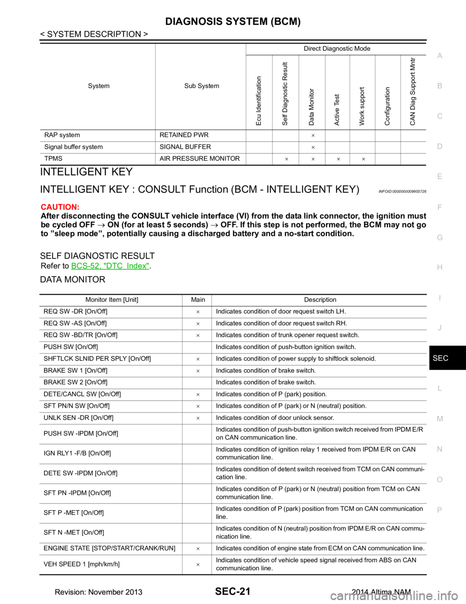
INTELLIGENT KEY
INTELLIGENT KEY : CONSULT Func tion (BCM - INTELLIGENT KEY)INFOID:0000000009955726
CAUTION:
After disconnecting the CONSULT vehicle interface (VI) from the data link connector, the ignition must
be cycled OFF → ON (for at least 5 seconds) → OFF. If this step is not performed, the BCM may not go
to ”sleep mode”, potentiall y causing a discharged battery and a no-start condition.
SELF DIAGNOSTIC RESULT
Refer to BCS-52, "DTC Index".
DATA MONITOR
RAP system RETAINED PWR ×
Signal buffer system SIGNAL BUFFER ×
TPMS AIR PRESSURE MONITOR ××××
System Sub System
Direct Diagnostic Mode
Ecu Identification
Self Diagnostic Result
Data Monitor
Active Test
Work support
Configuration
CAN Diag Support Mntr
Monitor Item [Unit] Main Description
REQ SW -DR [On/Off] ×Indicates condition of door request switch LH.
REQ SW -AS [On/Off] ×Indicates condition of door request switch RH.
REQ SW -BD/TR [On/Off] ×Indicates condition of trunk opener request switch.
PUSH SW [On/Off] Indicates condition of push-button ignition switch.
SHFTLCK SLNID PER SPLY [On/Off] ×Indicates condition of power supply to shiftlock solenoid.
BRAKE SW 1 [On/Off] ×Indicates condition of brake switch.
BRAKE SW 2 [On/Off] Indicates condition of brake switch.
DETE/CANCL SW [On/Off] ×Indicates condition of P (park) position.
SFT PN/N SW [On/Off] ×Indicates condition of P (park) or N (neutral) position.
UNLK SEN -DR [On/Off] ×Indicates condition of door unlock sensor.
PUSH SW -IPDM [On/Off] Indicates condition of push-button ignition switch received from IPDM E/R
on CAN communication line.
IGN RLY1 -F/B [On/Off] Indicates condition of ignition relay 1 received from IPDM E/R on CAN
communication line.
DETE SW -IPDM [On/Off] Indicates condition of detent switch received from TCM on CAN communi-
cation line.
SFT PN -IPDM [On/Off] Indicates condition of P (park) or N (neutral) position from TCM on CAN
communication line.
SFT P -MET [On/Off] Indicates condition of P (park) position from TCM on CAN communication
line.
SFT N -MET [On/Off] Indicates condition of N (neutral) position from IPDM E/R on CAN commu-
nication line.
ENGINE STATE [STOP/START/CRANK/RUN] ×Indicates condition of engine state from ECM on CAN communication line.
VEH SPEED 1 [mph/km/h] ×Indicates condition of vehicle speed signal received from ABS on CAN
communication line.
Revision: November 20132014 Altima NAMRevision: November 20132014 Altima NAM
Page 3968 of 4801
SR-6
< BASIC INSPECTION >
COLLISION DIAGNOSIS
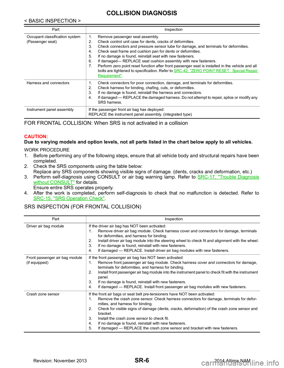
FOR FRONTAL COLLISION: When SRS is not activated in a collision
CAUTION:
Due to varying models and option levels, not all part s listed in the chart below apply to all vehicles.
WORK PROCEDURE
1. Before performing any of the following steps, ensur e that all vehicle body and structural repairs have been
completed.
2. Check the SRS components using the table below:
Replace any SRS components showing visible signs of damage. (dents, cracks and deformation, etc.)
3. Perform self-diagnosis using CONSULT or air bag warning lamp. Refer to SRC-17, "Trouble Diagnosis
without CONSULT" for details.
Ensure entire SRS operates properly.
4. After the work is completed, perform self-diagnosis to check that no malfunction is detected. Refer to
SRC-15, "SRS Operation Check"
.
SRS INSPECTION (FOR FRONTAL COLLISION)
Occupant classification system
(Passenger seat) 1. Remove passenger seat assembly.
2. Check control unit case for dents, cracks of deformities.
3. Check connectors and pressure sensor tube for damage, and terminals for deformities.
4. Check seat frame and cushion pan for dents or deformities.
5. If no damage is found, reinstall seat with new fasteners.
6. If damaged— REPLACE seat cushion assembly with new fasteners.
7. Perform zero point reset function after front passenger seat is installed in the vehicle and all bolts are tightened to specification. Refer to SRC-42, "ZERO POINT RESET : Special Repair
Requirement".
Harness and connectors 1. Check connectors for poor connection, damage, and terminals for deformities. 2. Check harness for binding, chafing, cuts, or deformities.
3. If no damage is found, reinstall the harness and connectors.
4. If damaged — REPLACE the damaged harness. Do not attempt to repair, splice or modify any SRS harness.
Instrument panel assembly If the passenger front air bag has deployed: REPLACE the instrument panel assembly. (integrated type)
Part Inspection
Part Inspection
Driver air bag module If the driver air bag has NOT been activated: 1. Remove driver air bag module. Check harness cover and connectors for damage, terminals for deformities, and harness for binding.
2. Install driver air bag module into the steering wheel to check fit and alignment with the wheel.
3. If no damage is found, reinstall with new fasteners.
4. If damaged — REPLACE. Install driver air bag modules with new fasteners.
Front passenger air bag module
(if equipped) If the front passenger air bag has NOT been activated:
1. Remove front passenger air bag module. Check harness cover and connectors for damage, terminals for deformities, and harness for binding.
2. Install front passenger air bag module into the instrument panel to check fit with the instrument panel.
3. If no damage is found, reinstall with new fasteners.
4. If damaged — REPLACE. Install front passenger air bag modules with new fasteners.
Crash zone sensor If the front air bags or seat belt pre-tensioners have NOT been activated: 1. Remove the crash zone sensor. Check harness connectors for damage, terminals for defor-mities, and harness for binding.
2. Check for visible signs of damage (dents, cracks, deformation) of the crash zone sensor and bracket.
3. Install the crash zone sensor to check fit.
4. If no damage is found, reinstall with new fasteners.
5. If damaged — REPLACE the crash zone sensor and bracket with new fasteners.
Revision: November 20132014 Altima NAM
Page 3969 of 4801
COLLISION DIAGNOSISSR-7
< BASIC INSPECTION >
C
D E
F
G
I
J
K L
M A
B
SR
N
O P
For Side and Rollover CollisionINFOID:0000000009463068
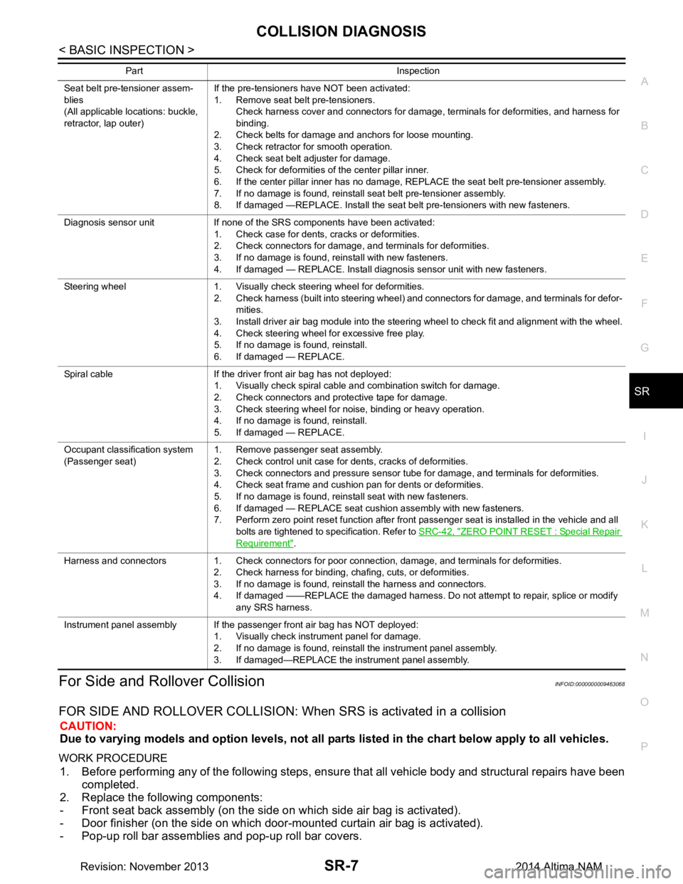
FOR SIDE AND ROLLOVER COLLISION: When SRS is activated in a collision
CAUTION:
Due to varying models and option levels, not all parts listed in the chart below apply to all vehicles.
WORK PROCEDURE
1. Before performing any of the following steps, ensur e that all vehicle body and structural repairs have been
completed.
2. Replace the following components:
- Front seat back assembly (on the side on which side air bag is activated).
- Door finisher (on the side on which door-mounted curtain air bag is activated).
- Pop-up roll bar assemblies and pop-up roll bar covers.
Seat belt pre-tensioner assem-
blies
(All applicable locations: buckle,
retractor, lap outer) If the pre-tensioners have NOT been activated:
1. Remove seat belt pre-tensioners.
Check harness cover and connectors for damage, terminals for deformities, and harness for
binding.
2. Check belts for damage and anchors for loose mounting.
3. Check retractor for smooth operation.
4. Check seat belt adjuster for damage.
5. Check for deformities of the center pillar inner.
6. If the center pillar inner has no damage, REPLACE the seat belt pre-tensioner assembly.
7. If no damage is found, reinstall seat belt pre-tensioner assembly.
8. If damaged —REPLACE. Install the seat belt pre-tensioners with new fasteners.
Diagnosis sensor unit If none of the SRS components have been activated: 1. Check case for dents, cracks or deformities.
2. Check connectors for damage, and terminals for deformities.
3. If no damage is found, reinstall with new fasteners.
4. If damaged — REPLACE. Install diagnosis sensor unit with new fasteners.
Steering wheel 1. Visually check steering wheel for deformities. 2. Check harness (built into steering wheel) and connectors for damage, and terminals for defor-mities.
3. Install driver air bag module into the steering wheel to check fit and alignment with the wheel.
4. Check steering wheel for excessive free play.
5. If no damage is found, reinstall.
6. If damaged — REPLACE.
Spiral cable If the driver front air bag has not deployed: 1. Visually check spiral cable and combination switch for damage.
2. Check connectors and protective tape for damage.
3. Check steering wheel for noise, binding or heavy operation.
4. If no damage is found, reinstall.
5. If damaged — REPLACE.
Occupant classification system
(Passenger seat) 1. Remove passenger seat assembly.
2. Check control unit case for dents, cracks of deformities.
3. Check connectors and pressure sensor tube for damage, and terminals for deformities.
4. Check seat frame and cushion pan for dents or deformities.
5. If no damage is found, reinstall seat with new fasteners.
6. If damaged — REPLACE seat cushion assembly with new fasteners.
7. Perform zero point reset function after front passenger seat is installed in the vehicle and all
bolts are tightened to specification. Refer to SRC-42, "ZERO POINT RESET : Special Repair
Requirement".
Harness and connectors 1. Check connectors for poor connection, damage, and terminals for deformities. 2. Check harness for binding, chafing, cuts, or deformities.
3. If no damage is found, reinstall the harness and connectors.
4. If damaged ——REPLACE the damaged harness. Do not attempt to repair, splice or modify any SRS harness.
Instrument panel assembly If the passenger front air bag has NOT deployed: 1. Visually check instrument panel for damage.
2. If no damage is found, reinstall the instrument panel assembly.
3. If damaged—REPLACE the instrument panel assembly.
Part Inspection
Revision: November 20132014 Altima NAM
Page 4002 of 4801
COMPONENT PARTSSRC-9
< SYSTEM DESCRIPTION >
C
D E
F
G
I
J
K L
M A
B
SRC
N
O P
Rear Side Air Bag Satellite SensorINFOID:0000000009460714
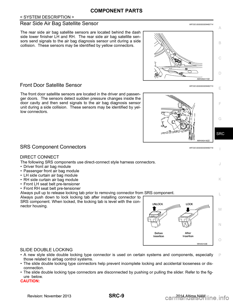
The rear side air bag satellite sensors are located behind the dash
side lower finisher LH and RH. The rear side air bag satellite sen-
sors send signals to the air bag diagnosis sensor unit during a side
collision. These sensors may be identified by yellow connectors.
Front Door Satellite SensorINFOID:0000000009460715
The front door satellite sensors are located in the driver and passen-
ger doors. The sensors detect sudden pressure changes inside the
door cavity and then send signals to the air bag diagnosis sensor
unit during a side collision. These sensors may be identified by yel-
low connectors.
SRS Component ConnectorsINFOID:0000000009460716
DIRECT CONNECT
The following SRS components use dire ct-connect style harness connectors.
• Driver front air bag module
• Passenger front air bag module
• LH side curtain air bag module
• RH side curtain air bag module
• Front LH seat belt pre-tensioner
• Front RH seat belt pre-tensioner
Always pull up to release locking tab prior to removing connector from SRS component.
Always push down to lock locking tab after installing connector to
SRS component. When locked, the locking tab is level with the con-
nector housing.
SLIDE DOUBLE LOCKING
• A new style slide double locking type connector is used on certain systems and components, especially those related to airbag control systems.
• The slide double locking type connectors help prevent incomplete locking and accidental looseness or dis- connection.
• The slide double locking type connectors are disconnected by pushing or pulling the slider. Refer to the fig-
ure below.
CAUTION:
AWHIA0417ZZ
AWHIA0418ZZ
WHIA0103E
Revision: November 20132014 Altima NAMRevision: November 20132014 Altima NAM
Page 4108 of 4801
PREPARATIONST-5
< PREPARATION >
C
D E
F
H I
J
K L
M A
B
ST
N
O P
PREPARATION
PREPARATION
Special Service ToolINFOID:0000000009461242
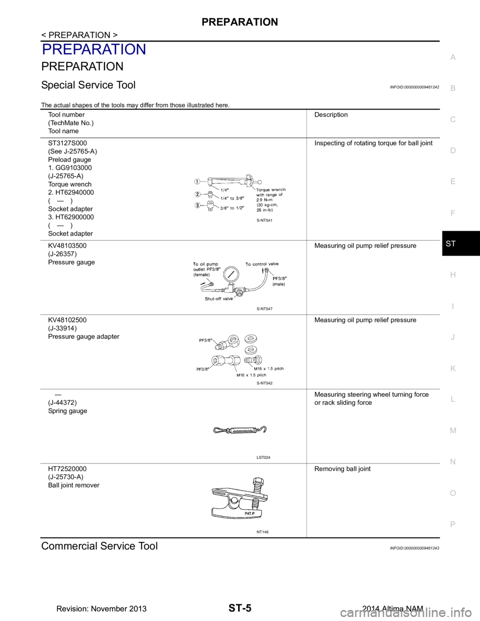
The actual shapes of the tools may differ from those illustrated here.
Commercial Service ToolINFOID:0000000009461243
Tool number
(TechMate No.)
Tool name Description
ST3127S000
(See J-25765-A)
Preload gauge
1. GG9103000
(J-25765-A)
Torque wrench
2. HT62940000
(—)
Socket adapter
3. HT62900000
(—)
Socket adapter Inspecting of rotating torque for ball joint
KV48103500
(J-26357)
Pressure gauge Measuring oil pump relief pressure
KV48102500
(J-33914)
Pressure gauge adapter Measuring oil pump relief pressure
—
(J-44372)
Spring gauge Measuring steering wheel turning force
or rack sliding force
HT72520000
(J-25730-A)
Ball joint remover Removing ball joint
S-NT541
S-NT547
S-NT542
LST024
NT146
Revision: November 20132014 Altima NAMRevision: November 20132014 Altima NAM