Page 4119 of 4801

ST-16
< BASIC INSPECTION >
STEERING WHEEL
STEERING WHEEL
InspectionINFOID:0000000009461252
CONDITION OF INSTALLATION
• Check installation condition of power steering gear assembly, front suspension, front drive shaft and steering
column.
• Check if movement exists when steering wheel is mo ved up and down, to the left and right and to the axial
direction.
• Verify that the power steering gear nuts are tightened to specification. Refer to ST-36, "Exploded View"
.
STEERING WHEEL PLAY
1. Turn tires straight ahead, start engine, then turn steer ing wheel to the left and right lightly. Measure steer-
ing wheel movement on the outer circumference of the steering wheel when it is turned to the point where
tires start moving.
NEUTRAL POSITION ON STEERING WHEEL
• Check neutral position on steering wheel after confirming that front wheel alignment is correct. Refer to FSU-
25, "Wheel Alignment (Unladen*1)".
1. Turn tires straight ahead, check if st eering wheel is in the neutral position.
2. If it is not in the neutral position, remo ve steering wheel and reinstall it correctly.
3. If the neutral position cannot be attained by repositi oning the steering wheel two teeth or less on steering
stem, loosen tie-rod lock nuts of power steering gear outer sockets, then adjust tie-rods by the same
amount in the opposite direction.
STEERING WHEEL TURNING FORCE
1. Park vehicle on a level, dry surface and set parking brake.
2. Start engine.
3. Bring power steering fluid up to operating temperature.
4. Verify that the tires are inflated to the specified pressure. Refer to WT-60, "Tire"
.
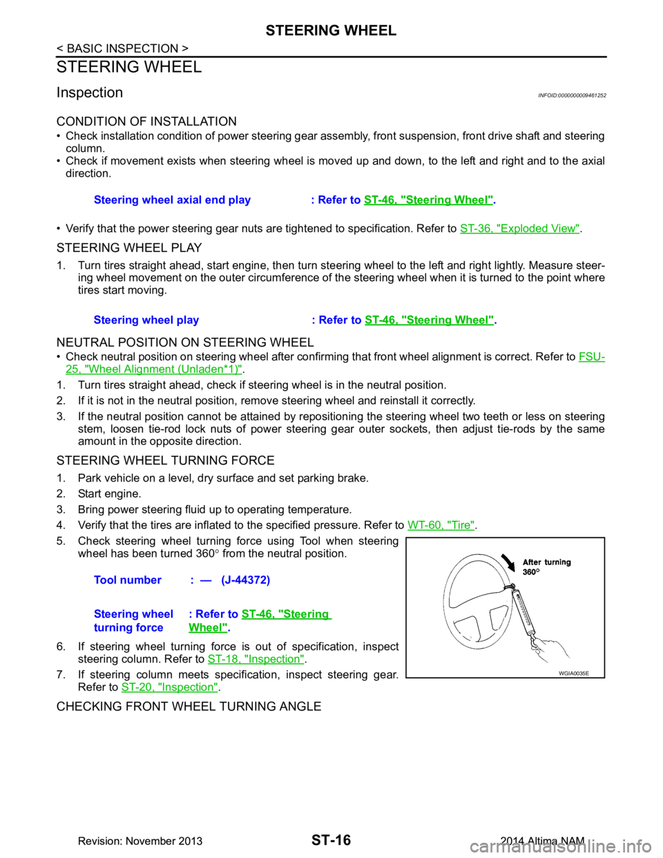
5. Check steering wheel turning force using Tool when steering wheel has been turned 360 ° from the neutral position.
6. If steering wheel turning force is out of specification, inspect steering column. Refer to ST-18, "Inspection"
.
7. If steering column meets specification, inspect steering gear. Refer to ST-20, "Inspection"
.
CHECKING FRONT WHEEL TURNING ANGLE
Steering wheel axial end play : Refer to ST-46, "Steering Wheel".
Steering wheel play : Refer to ST-46, "Steering Wheel"
.
Tool number : — (J-44372)
Steering wheel
turning force : Refer to
ST-46, "Steering
Wheel".
WGIA0035E
Revision: November 20132014 Altima NAMRevision: November 20132014 Altima NAM
Page 4122 of 4801

POWER STEERING OIL PUMPST-19
< BASIC INSPECTION >
C
D E
F
H I
J
K L
M A
B
ST
N
O P
POWER STEERING OIL PUMP
InspectionINFOID:0000000009461254
RELIEF OIL PRESSURE
CAUTION:
Make sure that belt tension is normal be fore starting the following procedure.
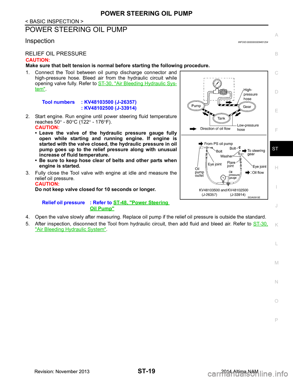
1. Connect the Tool between oil pump discharge connector and high-pressure hose. Bleed air from the hydraulic circuit while
opening valve fully. Refer to ST-30, "Air Bleeding Hydraulic Sys-
tem".
2. Start engine. Run engine until power steering fluid temperature reaches 50 ° - 80 °C (122 ° - 176 °F).
CAUTION:
• Leave the valve of the hydraulic pressure gauge fully open while starting and ru nning engine. If engine is
started with the valve closed, th e hydraulic pressure in oil
pump goes up to the relief pressure along with unusual
increase of fluid temperature.
• Be sure to keep hose clear of belts and other parts when engine is started.
3. Fully close the Tool valve with engine at idle and measure the relief oil pressure.
CAUTION:
Do not keep valve closed for 10 seconds or longer.
4. Open the valve slowly after measuring. Replace oil pump if the relief oil pressure is outside the standard.
5. After inspection, disconnect the Tool from hydraul ic circuit, then add fluid and bleed air. Refer to ST-30,
"Air Bleeding Hydraulic System".
Tool numbers : KV48103500 (J-26357)
: KV48102500 (J-33914)
Relief oil pressure : Refer to ST-48, "Power Steering
Oil Pump"
SGIA0915E
Revision: November 20132014 Altima NAMRevision: November 20132014 Altima NAM
Page 4133 of 4801

ST-30
< PERIODIC MAINTENANCE >
POWER STEERING FLUID
PERIODIC MAINTENANCE
POWER STEERING FLUID
Draining and RefillingINFOID:0000000009461266
DRAINING
1. Disconnect the high and low pressure piping from power steering gear.
2. Drain power steering fluid into a suitable container.
REFILLING
1. Fill power steering reservoir while checking power steering fluid level.
2. Bleed air from power steering hydraulic system. Refer to ST-30, "Air Bleeding Hydraulic System"
.
3. Check for power steering fluid leaks.
Air Bleeding Hydraulic SystemINFOID:0000000009461267
AIR BLEEDING HYDRAULIC SYSTEM
If air bleeding is not complete, excessive noise in the power steering oil pump will be present.
1. Make sure engine is off.
2. Turn the steering wheel from the full right stop pos ition and then to full left stop position several times.
Repeat until bubbles are no longer being generated in the reservoir.
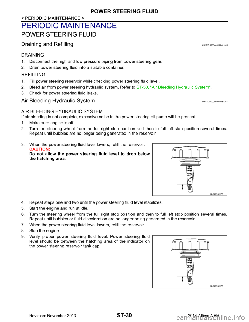
3. When the power steering fluid level lowers, refill the reservoir. CAUTION:
Do not allow the power steerin g fluid level to drop below
the hatching area.
4. Repeat steps one and two until the power steering fluid level stabilizes.
5. Start the engine and run at idle.
6. Turn the steering wheel from the full right stop pos ition and then to full left stop position several times.
Repeat until bubbles or fluid discoloration are no longer being generated in the reservoir.
7. When the power steering fluid level lowers, refill the reservoir.
8. Stop the engine.
9. Verify proper power steering fluid level. Power steering fluid level should be between the hatching area of the indicator on
the power steering reservoir tank cap.
ALGIA0125ZZ
ALGIA0125ZZ
Revision: November 20132014 Altima NAMRevision: November 20132014 Altima NAM
Page 4140 of 4801

STEERING GEAR AND LINKAGEST-37
< REMOVAL AND INSTALLATION >
C
D E
F
H I
J
K L
M A
B
ST
N
O P
6. Remove front exhaust tube. Refer to EX-5, "Exploded View" (QR25DE), EX-10, "Exploded View"
(VQ35DE).
7. Disconnect the high and low pressure piping from the steering gear assembly.
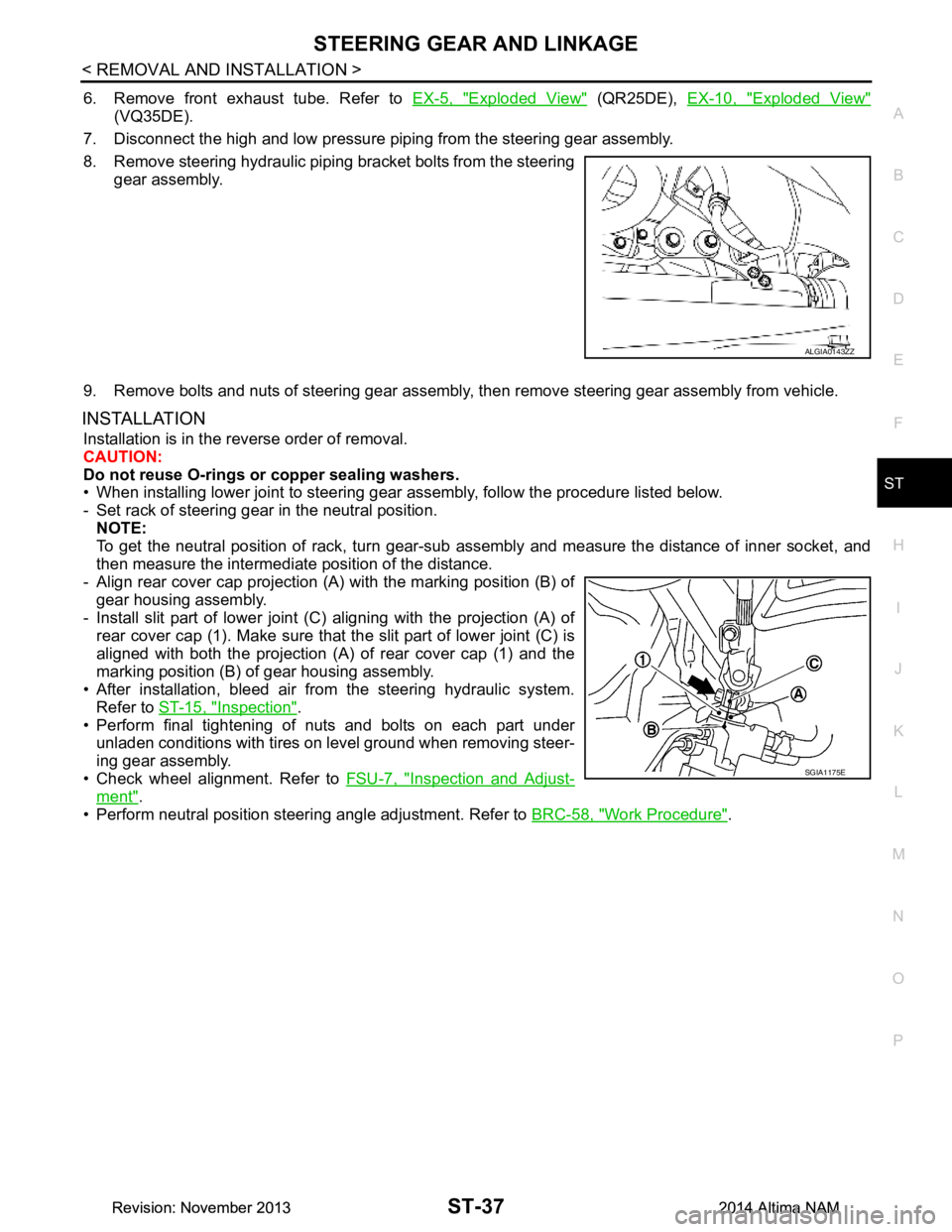
8. Remove steering hydraulic piping bracket bolts from the steering gear assembly.
9. Remove bolts and nuts of steering gear assembly, then remove steering gear assembly from vehicle.
INSTALLATION
Installation is in the reverse order of removal.
CAUTION:
Do not reuse O-rings or copper sealing washers.
• When installing lower joint to steering gear assembly, follow the procedure listed below.
- Set rack of steering gear in the neutral position. NOTE:
To get the neutral position of rack, turn gear-sub a ssembly and measure the distance of inner socket, and
then measure the intermediat e position of the distance.
- Align rear cover cap projection (A) with the marking position (B) of
gear housing assembly.
- Install slit part of lower joint (C) aligning with the projection (A) of
rear cover cap (1). Make sure that the slit part of lower joint (C) is
aligned with both the projection (A) of rear cover cap (1) and the
marking position (B) of gear housing assembly.
• After installation, bleed air from the steering hydraulic system. Refer to ST-15, "Inspection"
.
• Perform final tightening of nuts and bolts on each part under
unladen conditions with tires on level ground when removing steer-
ing gear assembly.
• Check wheel alignment. Refer to FSU-7, "Inspection and Adjust-
ment".
• Perform neutral position steering angle adjustment. Refer to BRC-58, "Work Procedure"
.
ALGIA0143ZZ
SGIA1175E
Revision: November 20132014 Altima NAMRevision: November 20132014 Altima NAM
Page 4141 of 4801
ST-38
< REMOVAL AND INSTALLATION >
POWER STEERING OIL PUMP
POWER STEERING OIL PUMP
Exploded ViewINFOID:0000000009461274
Removal and InstallationINFOID:0000000009461275
NOTE:
When removing components such as hoses, tubes/lines, etc. , cap or plug openings to prevent fluid from spill-
ing.
REMOVAL
1. Remove the power steering oil pump cover (1).
2. Drain power steering fluid. Refer to ST-30, "Draining and Refilling"
.
3. Remove the bolt from the power steering pressure line bracket.
1. Power steering reservoir cap 2. Power steering oil pump assembly 3. Low pressure piping
4. High pressure piping Front
ALGIA0145GB
ALGIA0132ZZ
Revision: November 20132014 Altima NAMRevision: November 20132014 Altima NAM
Page 4142 of 4801
POWER STEERING OIL PUMPST-39
< REMOVAL AND INSTALLATION >
C
D E
F
H I
J
K L
M A
B
ST
N
O P
4. Disconnect the following components from the power steering oil pump:
• LH power steering pump connector (A).
• Reservoir hose (B).
• RH power steering pump connector (C).
• High pressure piping (D).
5. Remove power steering oil pump bolts, then remove power steering oil pump.
INSTALLATION
Installation is in the reverse order of removal.
1. Install power steering pressure line to power steering oil pump. • Install power steering pressure line hold down bolt hand tight.
• Install power steering pressure line bracket and tighten to specified torque.
• Tighten power steering pressure line hold down bolt to specified torque.
2. Bleed air from power steering system. CAUTION:
Do not reuse O-rings.
ALGIA0148ZZ
Revision: November 20132014 Altima NAMRevision: November 20132014 Altima NAM
Page 4143 of 4801
ST-40
< REMOVAL AND INSTALLATION >
HYDRAULIC LINE
HYDRAULIC LINE
Exploded ViewINFOID:0000000009461276
QR25DE
ALGIA0133GB
1. Power steering pump assembly 2. High pressure piping (upper) 3. High pressure piping (lower)
4. Power steering gear assembly 5. Low pressure piping (lower) 6. Low pressure piping (upper)
A. View A B. View B Front
Revision: November 20132014 Altima NAMRevision: November 20132014 Altima NAM
Page 4144 of 4801
HYDRAULIC LINEST-41
< REMOVAL AND INSTALLATION >
C
D E
F
H I
J
K L
M A
B
ST
N
O P
VQ35DE
Removal and InstallationINFOID:0000000009461277
NOTE:
When removing components such as hoses, tubes/lines, etc. , cap or plug openings to prevent fluid from spill-
ing.
REMOVAL
ALGIA0134GB
1. Power steering pump assembly 2. High pressure piping (upper) 3. Low pressure piping (lower)
4. Power steering gear assembly 5. Low pressure piping (lower) 6. Low pressure piping (upper)
7. Engine mount bracket A. View A B. View B
Front
Revision: November 20132014 Altima NAMRevision: November 20132014 Altima NAM