2014 NISSAN TEANA Pressure
[x] Cancel search: PressurePage 2642 of 4801
HA-36
< REMOVAL AND INSTALLATION >
COOLER PIPE AND HOSE
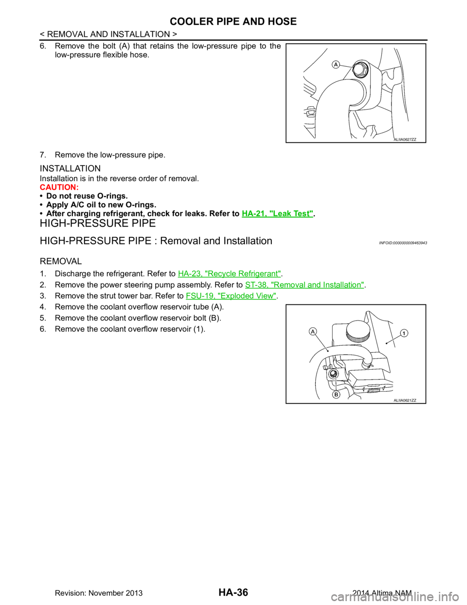
6. Remove the bolt (A) that retains the low-pressure pipe to thelow-pressure flexible hose.
7. Remove the low-pressure pipe.
INSTALLATION
Installation is in the reverse order of removal.
CAUTION:
• Do not reuse O-rings.
• Apply A/C oil to new O-rings.
• After charging refrigerant, check for leaks. Refer to HA-21, "Leak Test"
.
HIGH-PRESSURE PIPE
HIGH-PRESSURE PIPE : Removal and InstallationINFOID:0000000009463943
REMOVAL
1. Discharge the refrigerant. Refer to HA-23, "Recycle Refrigerant".
2. Remove the power steering pump assembly. Refer to ST-38, "Removal and Installation"
.
3. Remove the strut tower bar. Refer to FSU-19, "Exploded View"
.
4. Remove the coolant overflow reservoir tube (A).
5. Remove the coolant overflow reservoir bolt (B).
6. Remove the coolant overflow reservoir (1).
ALIIA0627ZZ
ALIIA0621ZZ
Revision: November 20132014 Altima NAM
Page 2643 of 4801
COOLER PIPE AND HOSEHA-37
< REMOVAL AND INSTALLATION >
C
D E
F
G H
J
K L
M A
B
HA
N
O P
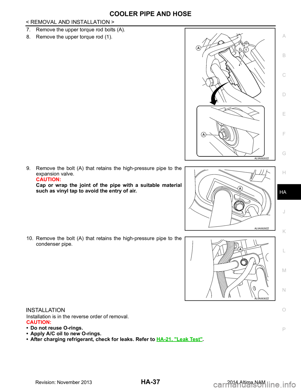
7. Remove the upper torque rod bolts (A).
8. Remove the upper torque rod (1).
9. Remove the bolt (A) that retains the high-pressure pipe to the expansion valve.
CAUTION:
Cap or wrap the joint of the pipe with a suitable material
such as vinyl tap to avo id the entry of air.
10. Remove the bolt (A) that retains the high-pressure pipe to the condenser pipe.
INSTALLATION
Installation is in the reverse order of removal.
CAUTION:
• Do not reuse O-rings.
• Apply A/C oil to new O-rings.
• After charging refrigerant, check for leaks. Refer to HA-21, "Leak Test"
.
ALIIA0620ZZ
ALIIA0629ZZ
ALIIA0630ZZ
Revision: November 20132014 Altima NAM
Page 2644 of 4801
HA-38
< REMOVAL AND INSTALLATION >
CONDENSER
CONDENSER
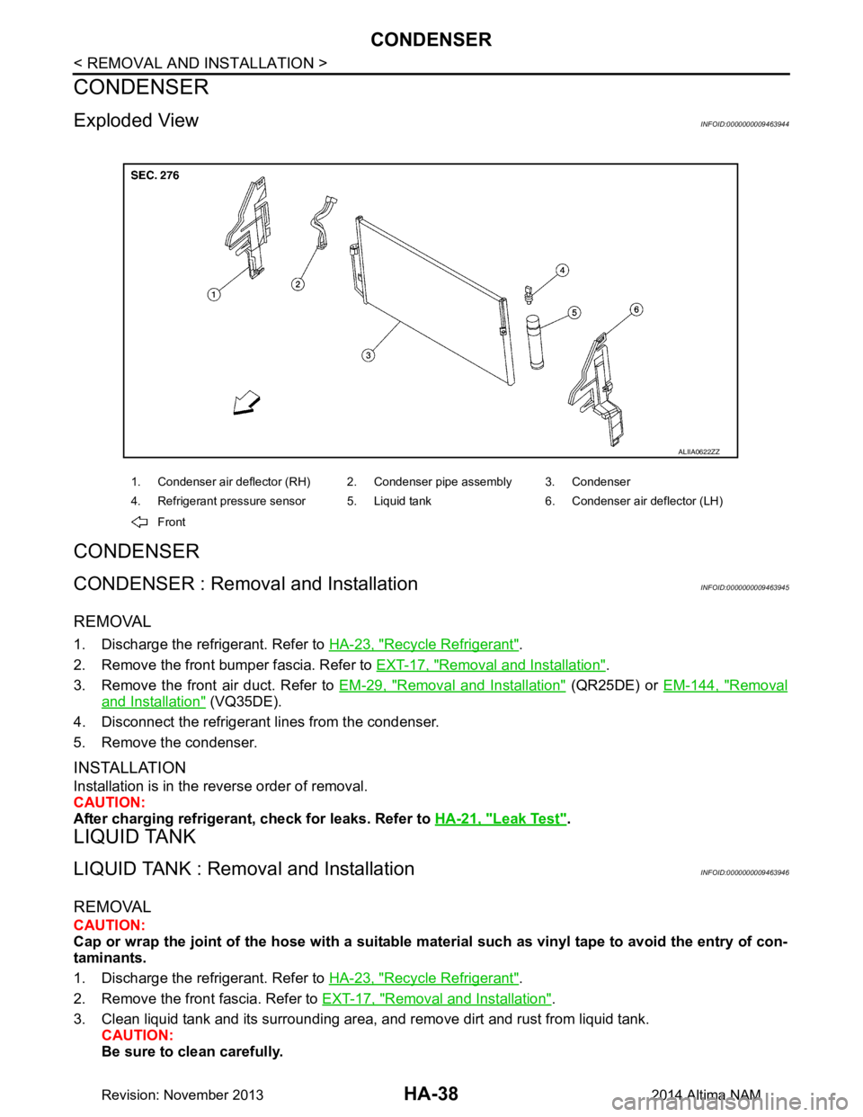
Exploded ViewINFOID:0000000009463944
CONDENSER
CONDENSER : Removal and InstallationINFOID:0000000009463945
REMOVAL
1. Discharge the refrigerant. Refer to HA-23, "Recycle Refrigerant".
2. Remove the front bumper fascia. Refer to EXT-17, "Removal and Installation"
.
3. Remove the front air duct. Refer to EM-29, "Removal and Installation"
(QR25DE) or EM-144, "Removal
and Installation" (VQ35DE).
4. Disconnect the refrigerant lines from the condenser.
5. Remove the condenser.
INSTALLATION
Installation is in the reverse order of removal.
CAUTION:
After charging refrigerant, check for leaks. Refer to HA-21, "Leak Test"
.
LIQUID TANK
LIQUID TANK : Removal and InstallationINFOID:0000000009463946
REMOVAL
CAUTION:
Cap or wrap the joint of the hose with a suitable ma terial such as vinyl tape to avoid the entry of con-
taminants.
1. Discharge the refrigerant. Refer to HA-23, "Recycle Refrigerant"
.
2. Remove the front fascia. Refer to EXT-17, "Removal and Installation"
.
3. Clean liquid tank and its surrounding area, and remove dirt and rust from liquid tank. CAUTION:
Be sure to clean carefully.
1. Condenser air deflector (RH) 2. Condenser pipe assembly 3. Condenser
4. Refrigerant pressure sensor 5. Liquid tank 6. Condenser air deflector (LH)
Front
ALIIA0622ZZ
Revision: November 20132014 Altima NAM
Page 2645 of 4801
CONDENSERHA-39
< REMOVAL AND INSTALLATION >
C
D E
F
G H
J
K L
M A
B
HA
N
O P
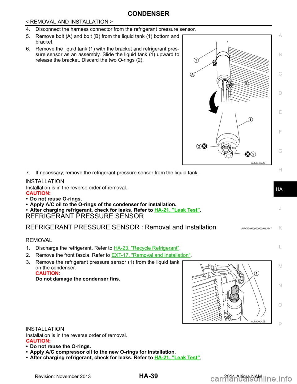
4. Disconnect the harness connector from the refrigerant pressure sensor.
5. Remove bolt (A) and bolt (B) from the liquid tank (1) bottom and bracket.
6. Remove the liquid tank (1) with the bracket and refrigerant pres-
sure sensor as an assembly. Slide the liquid tank (1) upward to
release the bracket. Discard the two O-rings (2).
7. If necessary, remove the refrigerant pressure sensor from the liquid tank.
INSTALLATION
Installation is in the reverse order of removal.
CAUTION:
• Do not reuse O-rings.
• Apply A/C oil to the O-rings of the condenser for installation.
• After charging refrigerant, check for leaks. Refer to HA-21, "Leak Test"
.
REFRIGERANT PRESSURE SENSOR
REFRIGERANT PRESSURE SENSOR : Removal and InstallationINFOID:0000000009463947
REMOVAL
1. Discharge the refrigerant. Refer to HA-23, "Recycle Refrigerant".
2. Remove the front fascia. Refer to EXT-17, "Removal and Installation"
.
3. Remove the refrigerant pressure sensor (1) from the liquid tank on the condenser.
CAUTION:
Do not damage the condenser fins.
INSTALLATION
Installation is in the reverse order of removal.
CAUTION:
• Do not reuse the O-rings.
• Apply A/C compressor oil to th e new O-rings for installation.
• After charging refrigerant, check for leaks. Refer to HA-21, "Leak Test"
.
ALIIA0422ZZ
ALIIA0004ZZ
Revision: November 20132014 Altima NAM
Page 2647 of 4801
HEATING AND COOLING UNIT ASSEMBLYHA-41
< REMOVAL AND INSTALLATION >
C
D E
F
G H
J
K L
M A
B
HA
N
O P
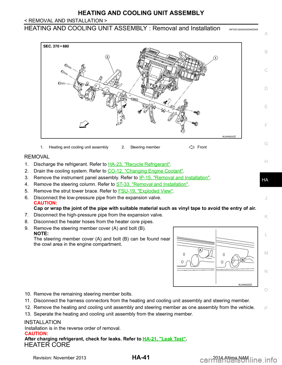
HEATING AND COOLING UNIT ASSEMB LY : Removal and InstallationINFOID:0000000009463949
REMOVAL
1. Discharge the refrigerant. Refer to HA-23, "Recycle Refrigerant".
2. Drain the cooling system. Refer to CO-12, "Changing Engine Coolant"
.
3. Remove the instrument panel assembly. Refer to IP-15, "Removal and Installation"
.
4. Remove the steering column. Refer to ST-33, "Removal and Installation"
.
5. Remove the strut tower brace. Refer to FSU-19, "Exploded View"
.
6. Disconnect the low-pressure pipe from the expansion valve. CAUTION:
Cap or wrap the joint of the pipe with suitable ma terial such as vinyl tape to avoid the entry of air.
7. Disconnect the high-pressure pi pe from the expansion valve.
8. Disconnect the heater hoses from the heater core pipes.
9. Remove the steering member cover (A) and bolt (B). NOTE:
The steering member cover (A) and bolt (B) can be found near
the cowl area in the engine compartment.
10. Remove the remaining steering member bolts.
11. Disconnect the harness connectors from the heati ng and cooling unit assembly and steering member.
12. Remove the heating and cooling unit assembly and steering member as one assembly from the vehicle.
13. Seperate the heating and cooling unit assembly from the steering member.
INSTALLATION
Installation is in the reverse order of removal.
CAUTION:
After charging refrigerant, check for leaks. Refer to HA-21, "Leak Test"
.
HEATER CORE
1. Heating and cooling unit assembly 2. Steering member Front
ALIIA0624ZZ
ALIIA0623ZZ
Revision: November 20132014 Altima NAM
Page 2648 of 4801
HA-42
< REMOVAL AND INSTALLATION >
HEATING AND COOLING UNIT ASSEMBLY
HEATER CORE : Removal and Installation
INFOID:0000000009463950
REMOVAL
1. Remove the heating and cooling unit assembly. Refer to HA-41, "HEATING AND COOLING UNIT
ASSEMBLY : Removal and Installation".
2. Remove the heater core pipes cover. Refer to HA-40, "Exploded View"
.
3. Disconnect the harness connector from the blower motor.
4. Remove the heater core.
INSTALLATION
Installation is in the reverse order of removal.
EVAPORATOR
EVAPORATOR : Removal and InstallationINFOID:0000000009463951
REMOVAL
1. Remove the heater core. Refer to HA-42, "HEATER CORE : Removal and Installation".
2. Remove the upper floor connecting duct (RH). Refer to HA-40, "Exploded View"
.
3. Remove the air mix door motor (driver). Refer to HAC-109, "AIR MIX DOOR MOTOR : Removal and
Installation - Air Mix Door Motor (RH)".
4. Remove the air mix door motor (passenger) (if equipped). Refer to HAC-109, "AIR MIX DOOR MOTOR :
Removal and Installation - Air Mix Door Motor (LH)"
5. Disconnect the harness connector from the intake sensor.
6. Remove the evaporator and expansion valve assembly.
INSTALLATION
Installation is in the reverse order of removal.
NOTE:
The evaporator can only be ordered as an assembly with the expansion valve.
EXPANSION VALVE
EXPANSION VALVE : Removal and Installation for Expansion ValveINFOID:0000000009463952
REMOVAL
1. Discharge the refrigerant. Refer to HA-23, "Recycle Refrigerant".
2. Remove the strut tower brace. Refer to FSU-19, "Exploded View"
.
3. Disconnect the low-pressure pipe from the expansion valve.
4. Disconnect the high-pressure pipe from the expansion valve.
5. Remove the expansion valve bolts.
6. Remove the expansion valve.
INSTALLATION
Installation is in the reverse order of removal.
CAUTION:
After charging refrigerant, check for leaks. Refer to HA-21, "Leak Test"
.
Revision: November 20132014 Altima NAM
Page 2652 of 4801

HAC-3
C
D E
F
G H
J
K L
M A
B
HAC
N
O P
AMBIENT SENSOR ....................................... ..103
Removal and Installation .......................................103
IN-VEHICLE SENSOR ................................... ..104
Removal and Installation .......................................104
SUNLOAD SENSOR ...................................... ..105
Removal and Installation .......................................105
INTAKE SENSOR .......................................... ..106
Removal and Installation .......................................106
REFRIGERANT PRESSURE SENSOR ......... ..107
Removal and Installation .......................................107
DOOR MOTOR ............................................... ..108
Exploded View .................................................... ..108
INTAKE DOOR MOTOR ........................................ ..109
INTAKE DOOR MOTOR : Removal and Installa-
tion ...................................................................... ..
109
MODE DOOR MOTOR .......................................... ..109
MODE DOOR MOTOR : Removal and Installation ..109
AIR MIX DOOR MOTOR ....................................... ..109
AIR MIX DOOR MOTOR : Removal and Installa-
tion - Air Mix Door Motor (RH) ............................. ..
109
AIR MIX DOOR MOTOR : Removal and Installa-
tion - Air Mix Door Motor (LH) ............................. ..
109
MANUAL AIR CONDITIONER
PRECAUTION ................ ............................
110
PRECAUTIONS .............................................. ..110
Precaution for Supplemental Restraint System
(SRS) "AIR BAG" and "SEAT BELT PRE-TEN-
SIONER" ............................................................. ..
110
Precaution for Work ..............................................110
Working with HFC-134a (R-134a) .........................110
Precaution for Service Equipment .........................111
PREPARATION .........................................113
PREPARATION .............................................. ..113
Special Service Tool ........................................... ..113
Commercial Service Tool ......................................113
SYSTEM DESCRIPTION ...........................114
COMPONENT PARTS ................................... ..114
Component Part Location ................................... ..114
Component Description .........................................115
SYSTEM ...........................................................117
System Diagram .................................................. ..117
System Description ...............................................117
Air Flow Control .....................................................118
Air Inlet Control .....................................................118
Air Outlet Control ...................................................118
Compressor Control ..............................................118
Door Control ..........................................................119
Temperature Control ........................................... ..121
OPERATION ...................................................122
Switch Name and Function ....................................122
DIAGNOSIS SYSTEM (BCM) .........................124
CONSULT Function (BCM - COMMON ITEM) ......124
CONSULT Function (BCM - AIR CONDITIONER) ..125
DIAGNOSIS SYSTEM (IPDM E/R) .................126
CONSULT Function (IPDM E/R) ...........................126
ECU DIAGNOSIS INFORMATION ............128
FRONT AIR CONTROL ..................................128
Reference Value .................................................. ..128
ECM, IPDM E/R, BCM .....................................129
List of ECU Reference ...........................................129
WIRING DIAGRAM ....................................130
AIR CONDITIONER CONTROL ......................130
Wiring Diagram .................................................... ..130
BASIC INSPECTION .................................139
DIAGNOSIS AND REPAIR WORKFLOW ......139
Work Flow ............................................................ ..139
OPERATION INSPECTION ............................140
Work Procedure .....................................................140
DTC/CIRCUIT DIAGNOSIS .......................142
MODE DOOR MOTOR ....................................142
Diagnosis Procedure ........................................... ..142
AIR MIX DOOR MOTOR .................................144
Diagnosis Procedure .............................................144
INTAKE DOOR MOTOR .................................146
Diagnosis Procedure .............................................146
BLOWER MOTOR ..........................................148
Diagnosis Procedure .............................................148
Component Inspection (Blower Motor) ..................149
Component Inspection (Front Blower Motor Re-
lay) ....................................................................... ..
149
MAGNET CLUTCH .........................................151
Component Function Check ..................................151
Diagnosis Procedure .............................................151
POWER SUPPLY AND GROUND CIRCUIT
FOR FRONT AIR CONTROL ..........................
152
Description ........................................................... ..152
Component Function Check ..................................152
Diagnosis Procedure .............................................152
SYMPTOM DIAGNOSIS ............................154
Revision: November 20132014 Altima NAMRevision: November 20132014 Altima NAM
Page 2653 of 4801

HAC-4
HEATER AND AIR CONDITIONING SYSTEM
CONTROL SYMPTOMS ................................. .
154
Symptom Table ................................................... ..154
INSUFFICIENT COOLING ...............................155
Component Function Check ................................ ..155
INSUFFICIENT HEATING ...............................157
Component Function Check ................................ ..157
COMPRESSOR DOES NOT OPERATE .........159
Description ........................................................... ..159
Diagnosis Procedure .............................................159
REMOVAL AND INSTALLATION ..............161
FRONT AIR CONTROL .................................. .161
Removal and Installation ..................................... ..161
IN-VEHICLE SENSOR ......................................162
Removal and Installation .......................................162
REFRIGERANT PRESSURE SENSOR ......... ..163
Removal and Installation .......................................163
DOOR MOTOR ............................................... ..164
Exploded View ..................................................... .164
INTAKE DOOR MOTOR ........................................ .165
INTAKE DOOR MOTOR : Removal and Installa-
tion ....................................................................... .
165
MODE DOOR MOTOR ........................................... .165
MODE DOOR MOTOR : Removal and Installation .165
AIR MIX DOOR MOTOR ........................................ .165
AIR MIX DOOR MOTOR : Removal and Installa-
tion ....................................................................... .
165
Revision: November 20132014 Altima NAMRevision: November 20132014 Altima NAM