2014 NISSAN TEANA Pressure
[x] Cancel search: PressurePage 2611 of 4801
PRECAUTIONSHA-5
< PRECAUTION >
C
D E
F
G H
J
K L
M A
B
HA
N
O P
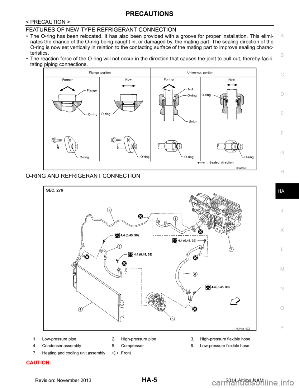
FEATURES OF NEW TYPE REFRIGERANT CONNECTION
• The O-ring has been relocated. It has also been provided with a groove for proper installation. This elimi- nates the chance of the O-ring being caught in, or damaged by, the mating part. The sealing direction of the
O-ring is now set vertically in relation to the contacti ng surface of the mating part to improve sealing charac-
teristics.
• The reaction force of the O-ring will not occur in the dire ction that causes the joint to pull out, thereby facili-
tating piping connections.
O-RING AND REFRIGERANT CONNECTION
CAUTION:
SHA815E
1. Low-pressure pipe 2. High-pressure pipe 3. High-pressure flexible hose
4. Condenser assembly 5. Compressor 6. Low-pressure flexible hose
7. Heating and cooling unit assembly Front
ALIIA0619ZZ
Revision: November 20132014 Altima NAM
Page 2612 of 4801
HA-6
< PRECAUTION >
PRECAUTIONS
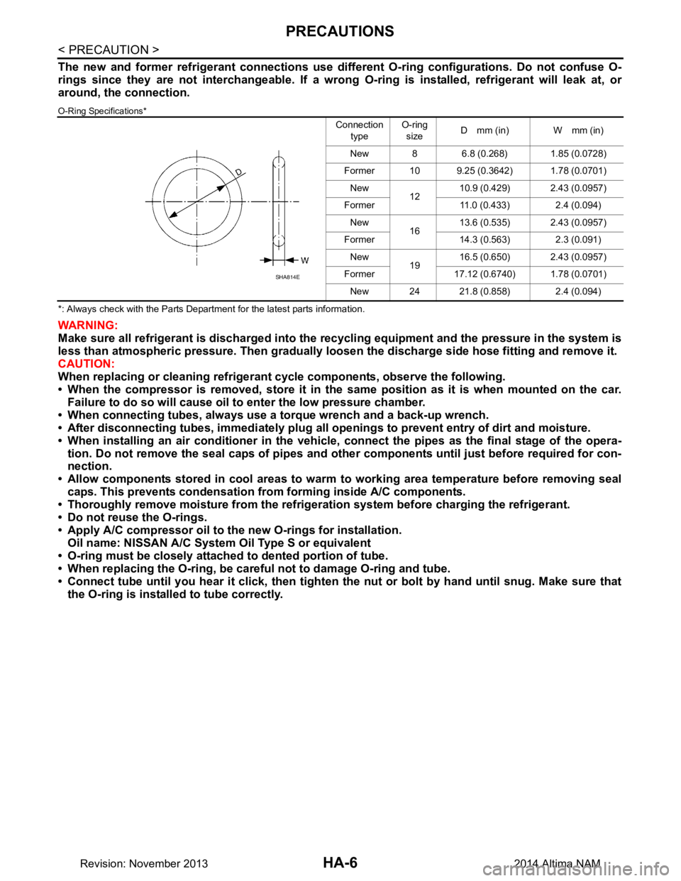
The new and former refrigerant connections use different O-ring configurations. Do not confuse O-
rings since they are not interchangeable. If a wrong O-ring is installed, refrigerant will leak at, or
around, the connection.
O-Ring Specifications*
*: Always check with the Parts Department for the latest parts information.
WARNING:
Make sure all refrigerant is discharged into the recycling equipment and the pressure in the system is
less than atmospheric pressure. Then gradually loo sen the discharge side hose fitting and remove it.
CAUTION:
When replacing or cleaning refrigeran t cycle components, observe the following.
• When the compressor is removed, store it in the same position as it is when mounted on the car.
Failure to do so will cause oil to enter the low pressure chamber.
• When connecting tubes, always use a torque wrench and a back-up wrench.
• After disconnecting tubes, immedi ately plug all openings to prevent entry of dirt and moisture.
• When installing an air conditioner in the vehicle, connect the pipes as the final stage of the opera-
tion. Do not remove the seal caps of pipes and othe r components until just before required for con-
nection.
• Allow components stored in cool areas to warm to working area temperature before removing seal
caps. This prevents condensation from forming inside A/C components.
• Thoroughly remove moisture from the refrigerat ion system before charging the refrigerant.
• Do not reuse the O-rings.
• Apply A/C compressor oil to th e new O-rings for installation.
Oil name: NISSAN A/C System Oil Type S or equivalent
• O-ring must be closely attached to dented portion of tube.
• When replacing the O-ring, be careful not to damage O-ring and tube.
• Connect tube until you hear it cl ick, then tighten the nut or bolt by hand until snug. Make sure that
the O-ring is installed to tube correctly.
Connection
type O-ring
size D mm (in) W mm (in)
New 8 6.8 (0.268) 1.85 (0.0728)
Former 10 9.25 (0.3642) 1.78 (0.0701) New 1210.9 (0.429) 2.43 (0.0957)
Former 11.0 (0.433) 2.4 (0.094) New 1613.6 (0.535) 2.43 (0.0957)
Former 14.3 (0.563) 2.3 (0.091) New 1916.5 (0.650) 2.43 (0.0957)
Former 17.12 (0.6740) 1.78 (0.0701) New 24 21.8 (0.858) 2.4 (0.094)
SHA814E
Revision: November 20132014 Altima NAM
Page 2613 of 4801
PRECAUTIONSHA-7
< PRECAUTION >
C
D E
F
G H
J
K L
M A
B
HA
N
O P
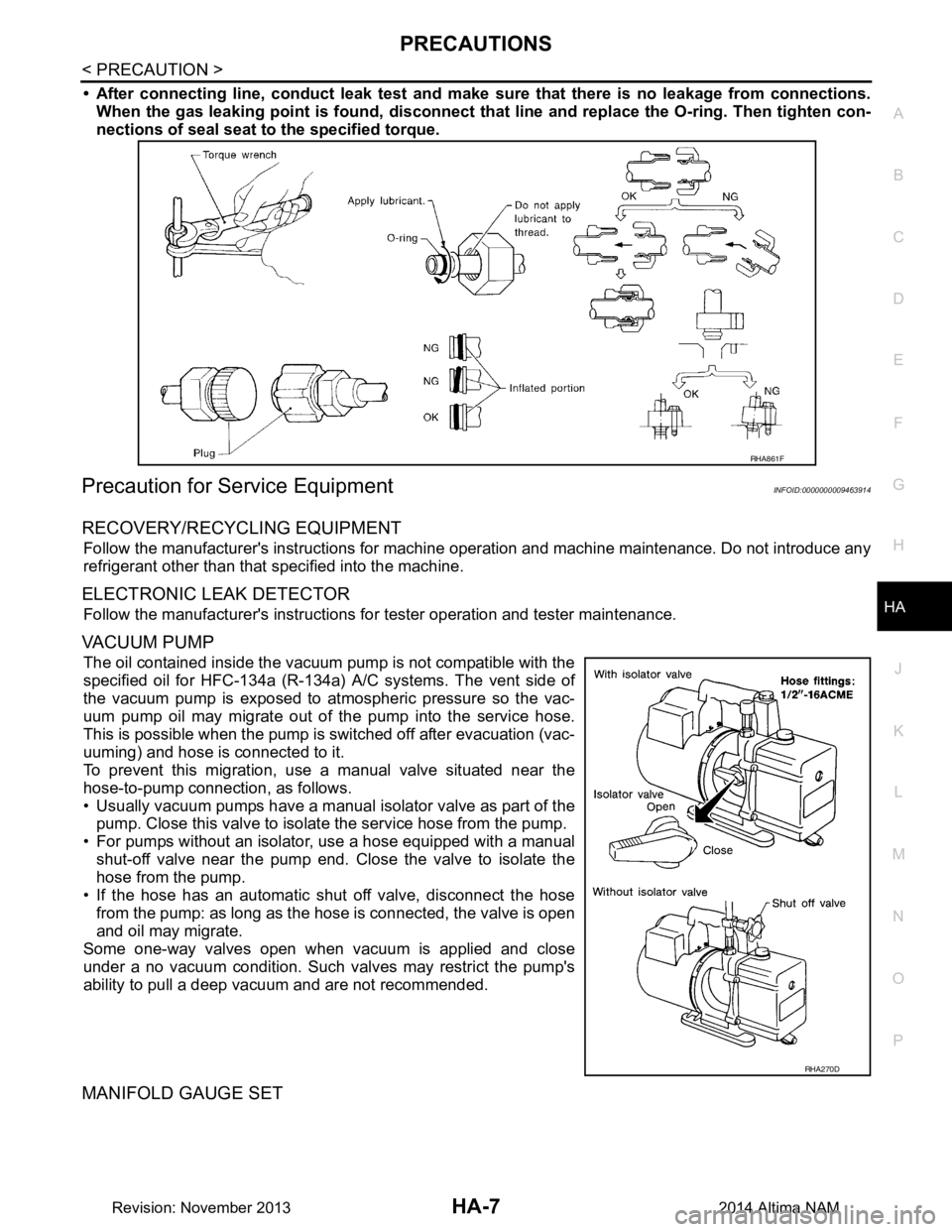
• After connecting line, conduct leak test and make sure that there is no leakage from connections.
When the gas leaking point is f ound, disconnect that line and replace the O-ring. Then tighten con-
nections of seal seat to the specified torque.
Precaution for Service EquipmentINFOID:0000000009463914
RECOVERY/RECYCLING EQUIPMENT
Follow the manufacturer's instructions for machine operation and machine maintenance. Do not introduce any
refrigerant other than that specified into the machine.
ELECTRONIC LEAK DETECTOR
Follow the manufacturer's instructions fo r tester operation and tester maintenance.
VACUUM PUMP
The oil contained inside the vacuum pump is not compatible with the
specified oil for HFC-134a (R-134a) A/C systems. The vent side of
the vacuum pump is exposed to atmospheric pressure so the vac-
uum pump oil may migrate out of the pump into the service hose.
This is possible when the pump is switched off after evacuation (vac-
uuming) and hose is connected to it.
To prevent this migration, use a manual valve situated near the
hose-to-pump connection, as follows.
• Usually vacuum pumps have a manual isolator valve as part of the
pump. Close this valve to isolate the service hose from the pump.
• For pumps without an isolator, use a hose equipped with a manual shut-off valve near the pump end. Close the valve to isolate the
hose from the pump.
• If the hose has an automatic shut off valve, disconnect the hose from the pump: as long as the hos e is connected, the valve is open
and oil may migrate.
Some one-way valves open when vacuum is applied and close
under a no vacuum condition. Such valves may restrict the pump's
ability to pull a deep vacuum and are not recommended.
MANIFOLD GAUGE SET
RHA861F
RHA270D
Revision: November 20132014 Altima NAM
Page 2619 of 4801
REFRIGERATION SYSTEMHA-13
< SYSTEM DESCRIPTION >
C
D E
F
G H
J
K L
M A
B
HA
N
O P
SYSTEM DESCRIPTION
REFRIGERATION SYSTEM
Refrigerant CycleINFOID:0000000009463918
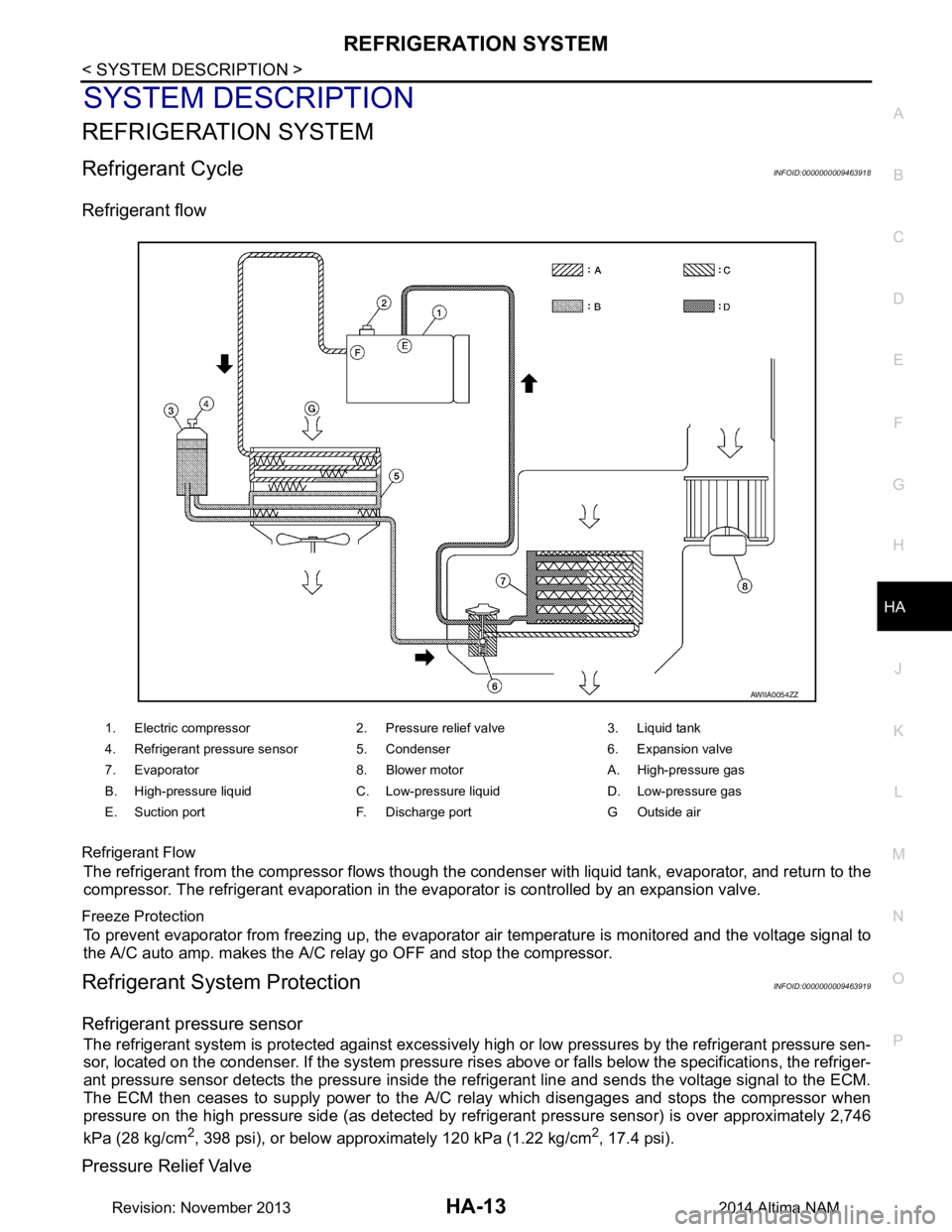
Refrigerant flow
Refrigerant Flow
The refrigerant from the compressor flows though the c ondenser with liquid tank, evaporator, and return to the
compressor. The refrigerant evaporation in the evaporator is controlled by an expansion valve.
Freeze Protection
To prevent evaporator from freezing up, the evaporator air temperature is monitored and the voltage signal to
the A/C auto amp. makes the A/C relay go OFF and stop the compressor.
Refrigerant System ProtectionINFOID:0000000009463919
Refrigerant pressure sensor
The refrigerant system is protected against excessively hi gh or low pressures by the refrigerant pressure sen-
sor, located on the condenser. If the system pressure rise s above or falls below the specifications, the refriger-
ant pressure sensor detects the pressure inside the refrigerant line and sends the voltage signal to the ECM.
The ECM then ceases to supply power to the A/C relay which disengages and stops the compressor when
pressure on the high pressure side (as detected by refr igerant pressure sensor) is over approximately 2,746
kPa (28 kg/cm
2, 398 psi), or below approximately 120 kPa (1.22 kg/cm2, 17.4 psi).
Pressure Relief Valve
1. Electric compressor 2. Pressure relief valve 3. Liquid tank
4. Refrigerant pressure sensor 5. Condenser 6. Expansion valve
7. Evaporator 8. Blower motor A. High-pressure gas
B. High-pressure liquid C. Low-pressure liquid D. Low-pressure gas
E. Suction port F. Discharge port G Outside air
AWIIA0054ZZ
Revision: November 20132014 Altima NAM
Page 2620 of 4801
HA-14
< SYSTEM DESCRIPTION >
REFRIGERATION SYSTEM
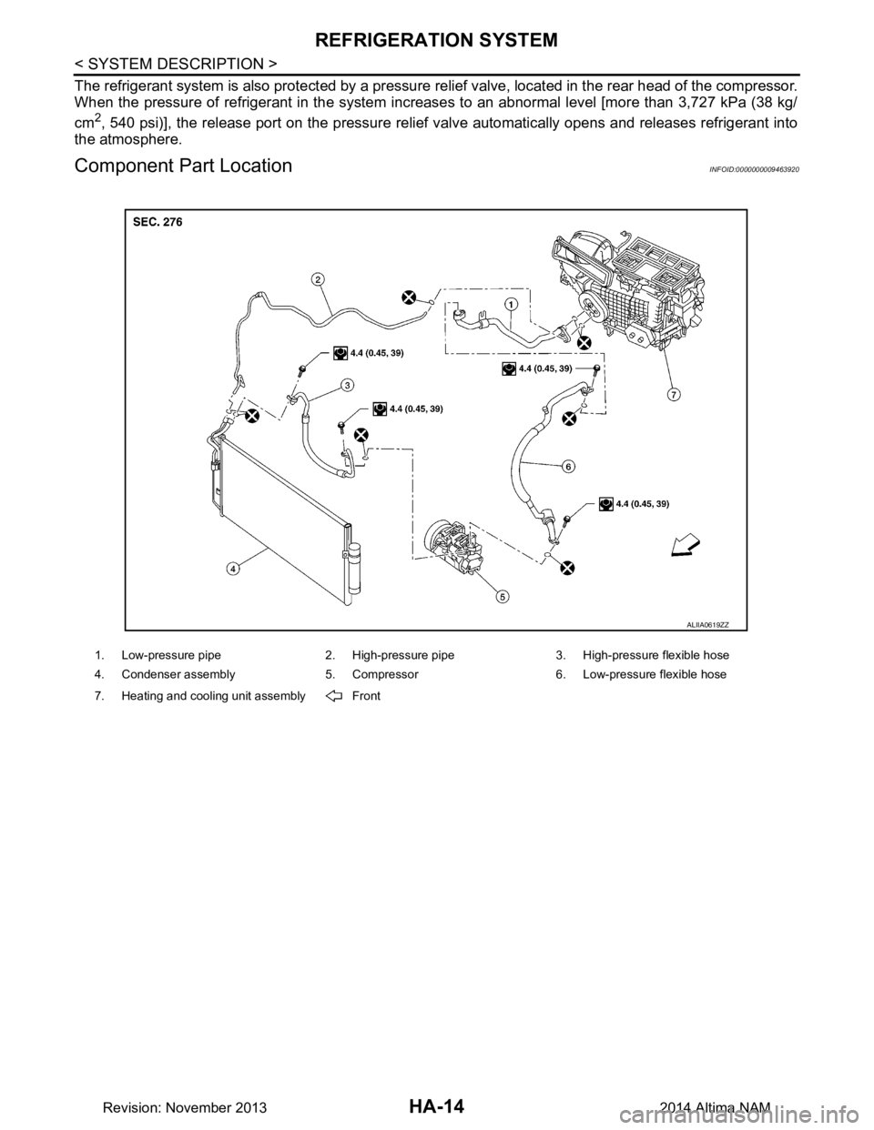
The refrigerant system is also protected by a pressure relief valve, located in the rear head of the compressor.
When the pressure of refrigerant in the system increases to an abnormal level [more than 3,727 kPa (38 kg/
cm
2, 540 psi)], the release port on the pressure relief valve automatically opens and releases refrigerant into
the atmosphere.
Component Part LocationINFOID:0000000009463920
1. Low-pressure pipe 2. High-pressure pipe 3. High-pressure flexible hose
4. Condenser assembly 5. Compressor 6. Low-pressure flexible hose
7. Heating and cooling unit assembly Front
ALIIA0619ZZ
Revision: November 20132014 Altima NAM
Page 2623 of 4801
HEATER AND AIR CONDITIONING SYSTEM SYMPTOMS
HA-17
< SYMPTOM DIAGNOSIS >
C
D E
F
G H
J
K L
M A
B
HA
N
O P
SYMPTOM DIAGNOSIS
HEATER AND AIR CONDITIONING SYSTEM SYMPTOMS
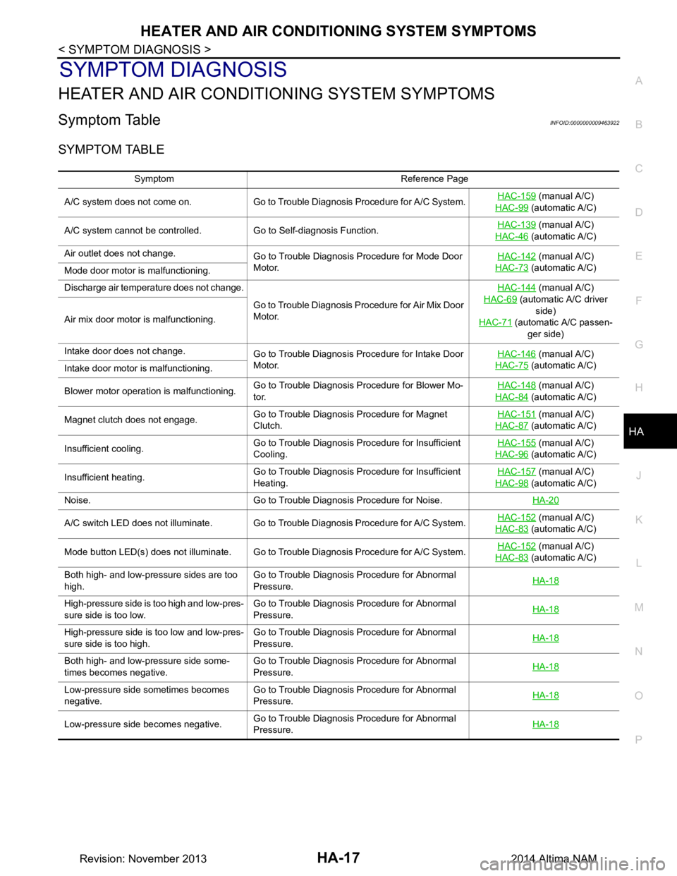
Symptom TableINFOID:0000000009463922
SYMPTOM TABLE
Symptom Reference Page
A/C system does not come on. Go to Trouble Diagnosis Procedure for A/C System. HAC-159
(manual A/C)
HAC-99
(automatic A/C)
A/C system cannot be controlled. Go to Self-diagnosis Function. HAC-139
(manual A/C)
HAC-46
(automatic A/C)
Air outlet does not change. Go to Trouble Diagnosis Procedure for Mode Door
Motor. HAC-142
(manual A/C)
HAC-73
(automatic A/C)
Mode door motor is malfunctioning.
Discharge air temperature does not change.
Go to Trouble Diagnosis Procedure for Air Mix Door
Motor. HAC-144
(manual A/C)
HAC-69
(automatic A/C driver side)
HAC-71
(automatic A/C passen-
ger side)
Air mix door motor is malfunctioning.
Intake door does not change.
Go to Trouble Diagnosis Procedure for Intake Door
Motor. HAC-146
(manual A/C)
HAC-75
(automatic A/C)
Intake door motor is malfunctioning.
Blower motor operation is malfunctioning. Go to Trouble Diagnosis Procedure for Blower Mo-
tor. HAC-148
(manual A/C)
HAC-84
(automatic A/C)
Magnet clutch does not engage. Go to Trouble Diagnosis Procedure for Magnet
Clutch. HAC-151
(manual A/C)
HAC-87
(automatic A/C)
Insufficient cooling. Go to Trouble Diagnosis Procedure for Insufficient
Cooling. HAC-155
(manual A/C)
HAC-96
(automatic A/C)
Insufficient heating. Go to Trouble Diagnosis Procedure for Insufficient
Heating. HAC-157
(manual A/C)
HAC-98
(automatic A/C)
Noise. Go to Trouble Diagnosis Procedure for Noise. HA-20
A/C switch LED does not illuminate. Go to Trouble Diagnosis Procedure for A/C System.HAC-152 (manual A/C)
HAC-83
(automatic A/C)
Mode button LED(s) does not illuminate. Go to Trouble Diagnosis Procedure for A/C System. HAC-152
(manual A/C)
HAC-83
(automatic A/C)
Both high- and low-pressure sides are too
high. Go to Trouble Diagnosis Procedure for Abnormal
Pressure. HA-18
High-pressure side is too high and low-pres-
sure side is too low. Go to Trouble Diagnosis Procedure for Abnormal
Pressure. HA-18
High-pressure side is too low and low-pres-
sure side is too high. Go to Trouble Diagnosis Procedure for Abnormal
Pressure. HA-18
Both high- and low-pressure side some-
times becomes negative. Go to Trouble Diagnosis Procedure for Abnormal
Pressure. HA-18
Low-pressure side sometimes becomes
negative. Go to Trouble Diagnosis Procedure for Abnormal
Pressure. HA-18
Low-pressure side becomes negative.
Go to Trouble Diagnosis Procedure for Abnormal
Pressure. HA-18
Revision: November 20132014 Altima NAM
Page 2624 of 4801
HA-18
< SYMPTOM DIAGNOSIS >
REFRIGERATION SYSTEM SYMPTOMS
REFRIGERATION SYSTEM SYMPTOMS
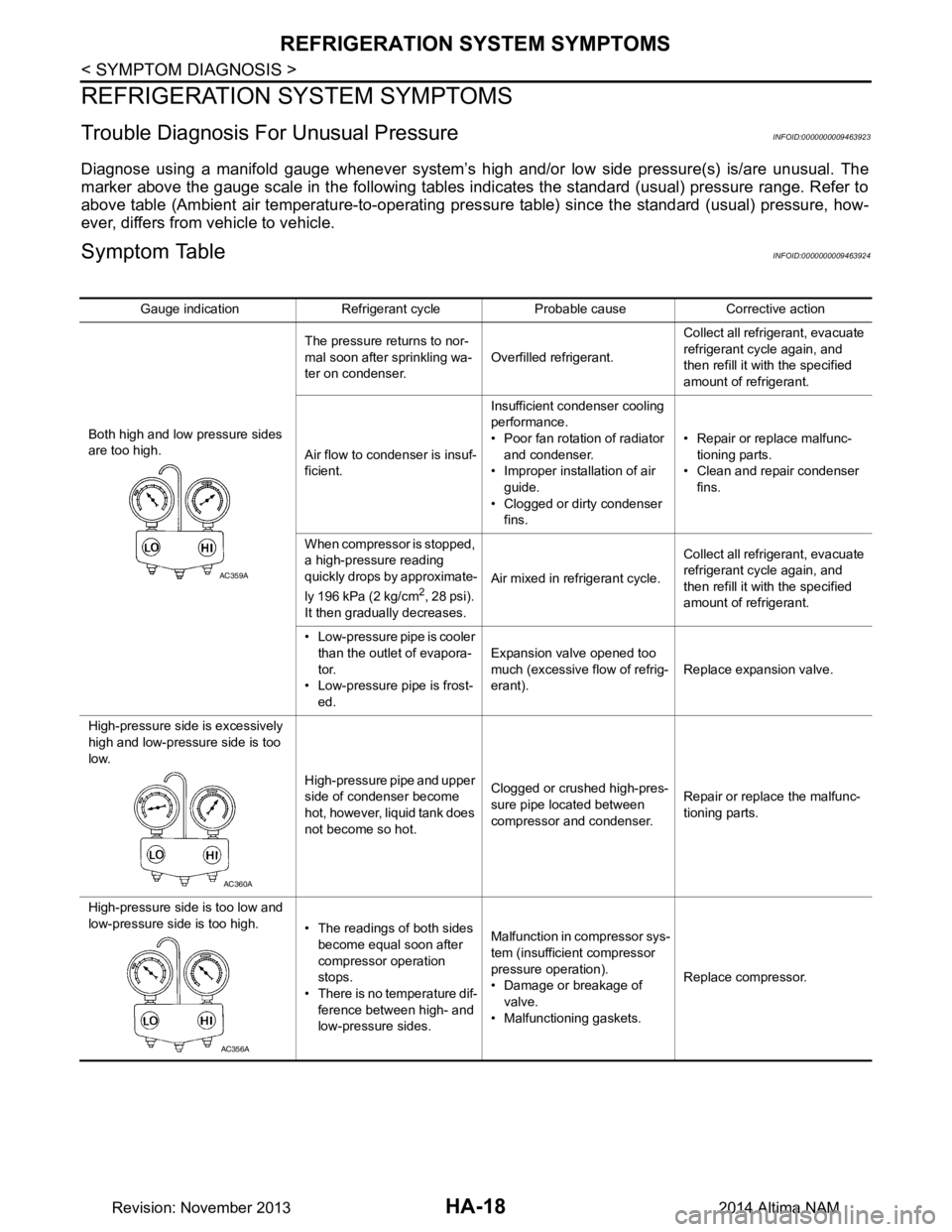
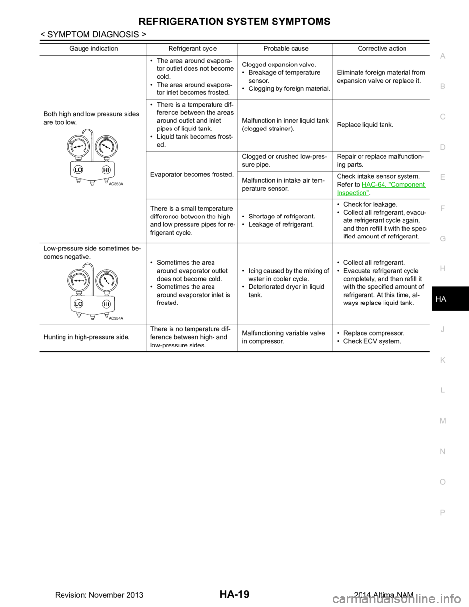
Trouble Diagnosis For Unusual PressureINFOID:0000000009463923
Diagnose using a manifold gauge whenever system’s high and/or low side pressure(s) is/are unusual. The
marker above the gauge scale in the following tables indicates the standard (usual) pressure range. Refer to
above table (Ambient air temperature-to-operating pres sure table) since the standard (usual) pressure, how-
ever, differs from vehicle to vehicle.
Symptom TableINFOID:0000000009463924
Gauge indication Refrigerant cycle Probable cause Corrective action
Both high and low pressure sides
are too high. The pressure returns to nor-
mal soon after sprinkling wa-
ter on condenser. Overfilled refrigerant. Collect all refrigerant, evacuate
refrigerant cycle again, and
then refill it with the specified
amount of refrigerant.
Air flow to condenser is insuf-
ficient. Insufficient condenser cooling
performance.
• Poor fan rotation of radiator and condenser.
• Improper installation of air
guide.
• Clogged or dirty condenser fins. • Repair or replace malfunc-
tioning parts.
• Clean and repair condenser
fins.
When compressor is stopped,
a high-pressure reading
quickly drops by approximate-
ly 196 kPa (2 kg/cm
2, 28 psi).
It then gradually decreases. Air mixed in refrigerant cycle.
Collect all refrigerant, evacuate
refrigerant cycle again, and
then refill it with the specified
amount of refrigerant.
• Low-pressure pipe is cooler than the outlet of evapora-
tor.
• Low-pressure pipe is frost- ed. Expansion valve opened too
much (excessive flow of refrig-
erant). Replace expansion valve.
High-pressure side is excessively
high and low-pressure side is too
low.
High-pressure pipe and upper
side of condenser become
hot, however, liquid tank does
not become so hot. Clogged or crushed high-pres-
sure pipe located between
compressor and condenser. Repair or replace the malfunc-
tioning parts.
High-pressure side is too low and
low-pressure side is too high. • The readings of both sides
become equal soon after
compressor operation
stops.
• There is no temperature dif- ference between high- and
low-pressure sides. Malfunction in compressor sys-
tem (insufficient compressor
pressure operation).
• Damage or breakage of
valve.
• Malfunctioning gaskets. Replace compressor.
AC359A
AC360A
AC356A
Revision: November 20132014 Altima NAM
Page 2625 of 4801
REFRIGERATION SYSTEM SYMPTOMSHA-19
< SYMPTOM DIAGNOSIS >
C
D E
F
G H
J
K L
M A
B
HA
N
O P
Both high and low pressure sides
are too low. • The area around evapora-
tor outlet does not become
cold.
• The area around evapora- tor inlet becomes frosted. Clogged expansion valve.
• Breakage of temperature sensor.
• Clogging by foreign material. Eliminate foreign material from
expansion valve or replace it.
• There is a temperature dif- ference between the areas
around outlet and inlet
pipes of liquid tank.
• Liquid tank becomes frost- ed. Malfunction in inner liquid tank
(clogged strainer). Replace liquid tank.
Evaporator becomes frosted. Clogged or crushed low-pres-
sure pipe. Repair or replace malfunction-
ing parts.
Malfunction in intake air tem-
perature sensor. Check intake sensor system.
Refer to HAC-64, "Component
Inspection".
There is a small temperature
difference between the high
and low pressure pipes for re-
frigerant cycle. • Shortage of refrigerant.
• Leakage of refrigerant. • Check for leakage.
• Collect all refrigerant, evacu-
ate refrigerant cycle again,
and then refill it with the spec-
ified amount of refrigerant.
Low-pressure side sometimes be-
comes negative. • Sometimes the area
around evaporator outlet
does not become cold.
• Sometimes the area
around evaporator inlet is
frosted. • Icing caused by the mixing of
water in cooler cycle.
• Deteriorated dryer in liquid
tank. • Collect all refrigerant.
• Evacuate refrigerant cycle completely, and then refill it
with the specified amount of
refrigerant. At this time, al-
ways replace liquid tank.
Hunting in high-pressure side. There is no temperature dif-
ference between high- and
low-pressure sides. Malfunctioning variable valve
in compressor. • Replace compressor.
• Check ECV system.
Gauge indication Refrigerant cycle Probable cause Corrective action
AC353A
AC354A
Revision: November 20132014 Altima NAM