Page 2494 of 4801

FL-14
< REMOVAL AND INSTALLATION >
EVAP CANISTER
EVAP CANISTER
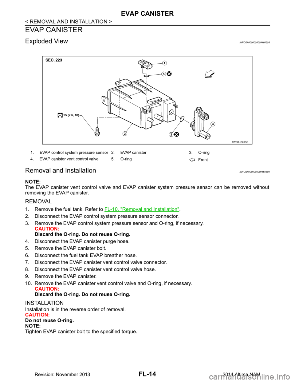
Exploded ViewINFOID:0000000009460608
Removal and InstallationINFOID:0000000009460609
NOTE:
The EVAP canister vent control valve and EVAP cani ster system pressure sensor can be removed without
removing the EVAP canister.
REMOVAL
1. Remove the fuel tank. Refer to FL-10, "Removal and Installation".
2. Disconnect the EVAP control system pressure sensor connector.
3. Remove the EVAP control system pressu re sensor and O-ring, if necessary.
CAUTION:
Discard the O-ring. Do not reuse O-ring.
4. Disconnect the EVAP canister purge hose.
5. Remove the EVAP canister bolt.
6. Disconnect the fuel tank EVAP breather hose.
7. Disconnect the EVAP canister vent control valve connector.
8. Disconnect the EVAP canister vent control valve hose.
9. Remove the EVAP canister.
10. Remove the EVAP canister vent c ontrol valve and O-ring, if necessary.
CAUTION:
Discard the O-ring. Do not reuse O-ring.
INSTALLATION
Installation is in the reverse order of removal.
CAUTION:
Do not reuse O-ring.
NOTE:
Tighten EVAP canister bolt to the specified torque.
1. EVAP control system pressure sensor 2. EVAP canister 3. O-ring
4. EVAP canister vent control valve 5. O-ring Front
AWBIA1320GB
Revision: November 20132014 Altima NAM
Page 2495 of 4801
EVAP CANISTERFL-15
< REMOVAL AND INSTALLATION >
C
D E
F
G H
I
J
K L
M A
FL
NP
O
InspectionINFOID:0000000009460610
Check EVAP canister as follows:
1. Block port (B).
2. Blow air into port (A) and check that it flows freely out of port (C).
3. Release blocked port (B).
4. Apply vacuum pressure to port (B) and check that vacuum pres-
sure exists at the ports (A) and (C).
5. Block port (A) and (B).
6. Apply pressure to port (C) and check that there is no leakage.
PBIB1212E
Revision: November 20132014 Altima NAM
Page 2497 of 4801
EVAP CANISTER VENT CONTROL VALVEFL-17
< REMOVAL AND INSTALLATION >
C
D E
F
G H
I
J
K L
M A
FL
NP
O
EVAP CANISTER VENT CONTROL VALVE
Exploded ViewINFOID:0000000009460613
Removal and InstallationINFOID:0000000009460614
NOTE:
The EVAP canister vent control valve and EVAP cani ster system pressure sensor can be removed without
removing the EVAP canister.
REMOVAL
1. Disconnect breather hose from EVAP canister.
2. Disconnect EVAP canister vent control valve.
3. Turn EVAP canister vent control valve counterclockwise.
4. Remove the EVAP canister vent control valve and O-ring. CAUTION:
Discard the O-ring. Do not reuse O-ring.
INSTALLATION
Installation is in the reverse order of removal.
CAUTION:
Do not reuse O-ring.
1. EVAP control system pressure sensor 2. EVAP canister 3. O-ring
4. EVAP canister vent control valve 5. O-ring
AWBIA1320GB
(A) : Lock
(B) : Unlock
PBIB3091E
Revision: November 20132014 Altima NAM
Page 2498 of 4801
FL-18
< REMOVAL AND INSTALLATION >
EVAP CONTROL SYSTEM PRESSURE SENSOR
EVAP CONTROL SYSTEM PRESSURE SENSOR
Exploded ViewINFOID:0000000009460615
Removal and InstallationINFOID:0000000009460616
NOTE:
The EVAP canister vent control valve and EVAP cani ster system pressure sensor can be removed without
removing the EVAP canister.
REMOVAL
1. Disconnect EVAP hose from EVAP canister.
2. Disconnect EVAP control system pressure sensor.
3. Remove EVAP control system pressure sensor and O-ring. CAUTION:
Discard the O-ring. Do not reuse O-ring.
INSTALLATION
Installation is in the reverse order of removal.
CAUTION:
Do not reuse O-ring.
1. EVAP control system pressure sensor 2. EVAP canister 3. O-ring
4. EVAP canister vent control valve 5. O-ring
AWBIA1320GB
Revision: November 20132014 Altima NAM
Page 2508 of 4801

FRONT SUSPENSION ASSEMBLYFSU-7
< PERIODIC MAINTENANCE >
C
D
F
G H
I
J
K L
M A
B
FSU
N
O P
PERIODIC MAINTENANCE
FRONT SUSPENSION ASSEMBLY
Inspection and AdjustmentINFOID:0000000009460626
INSPECTION
Make sure the mounting conditions (looseness, back lash) of each component and component conditions
(wear, damage) are normal.
LOWER BALL JOINT END PLAY
1. Set front wheels in a straight-ahead position. Do not depress brake pedal.
2. Place an iron bar or similar tool between upper link and steering knuckle.
3. Measure axial end play by prying it up and down.Refer to FSU-26, "Ball Joint"
.
CAUTION:
Be careful not to damage ball joint boot. Do not damage the installation position by applying
excessive force.
SHOCK ABSORBER
Check for oil leakage, damage and repl ace if malfunction is detected.
WHEEL ALIGNMENT
Description
Measure wheel alignment under unladen conditions.
NOTE:
"Unladen conditions" means that fuel, engine coolant, and lubricant are full. Spare tire, jack, hand tools and
mats are in designated positions.
General Information and Recommendations
• A four-wheel thrust alignment should be performed.
- This type of alignment is re commended for any NISSAN vehicle.
- The four-wheel "thrust" process helps ensure that t he vehicle is properly aligned and the steering wheel is
centered.
- The alignment rack itself should be capable of accepting any NISSAN vehicle.
- The rack should be checked to ensure that it is level.
• Make sure the machine is properly calibrated.
- Your alignment equipment should be regularly ca librated in order to give correct information.
- Check with the manufacturer of your specific equi pment for their recommended Service/Calibration Sched-
ule.
Preliminary Check
Check the following:
1. Tires for improper air pressure and wear.
2. Road wheels for runout. Refer to WT-60, "Road Wheel"
.
3. Wheel bearing axial end play. Refer to FAX-27, "Wheel Bearing"
.
4. Transverse link ball joint axial end play. Refer to FSU-11, "Removal and Installation"
.
5. Shock absorber operation.
6. Each mounting part of axle and suspension for looseness and deformation.
7. Each of suspension member, shock absorber, upper link and transverse link for cracks, deformation and other damage.
8. Vehicle height (posture).
Alignment Process
IMPORTANT:
Use only the alignment specificati ons listed in this Service Manual.
• When displaying the alignment settings, m any alignment machines use "indicators" Do not use these indi-
cators. : (Green/red, plus or minus, Go/No Go).
- The alignment specifications programmed into your machine that operate these indicators may not be cor-
rect.
Revision: November 20132014 Altima NAM
Page 2541 of 4801

ABBREVIATIONSGI-13
< HOW TO USE THIS MANUAL >
C
D E
F
G H
I
J
K L
M B
GI
N
O PABBREVIATIONS
Abbreviation ListINFOID:0000000009462979
The following ABBREVIATIONS are used:
A
B
C
D
ABBREVIATION DESCRIPTION A/C Air conditioner
A/C Air conditioning
A/F sensor Air fuel ratio sensor A/T Automatic transaxle/transmission
ABS Anti-lock braking system
ACCS Advance climate control system ACL Air cleaner
AP Accelerator pedal
APP Accelerator pedal position AV Audio visual
AVM Around view monitor
AWD All wheel drive
ABBREVIATION DESCRIPTION BARO Barometric pressureBCI Backup collision intervention
BCM Body control module
BLSD Brake limited slip differential BPP Brake pedal positionBSI Blind spot intervention
BSW Blind spot warning
ABBREVIATION DESCRIPTION CKP Crankshaft positionCL Closed loop
CMP Camshaft position CPP Clutch pedal positionCTP Closed throttle position
CVT Continuously variable transaxle/transmission
ABBREVIATION DESCRIPTION D
1Drive range first gear
D
2Drive range second gear
D
3Drive range third gear
D
4Drive range fourth gear
DCA Distance control assist
DDS Downhill drive support DFI Direct fuel injection system
DLC Data link connector
DTC Diagnostic trouble code
Revision: November 20132014 Altima NAMRevision: November 20132014 Altima NAM
Page 2542 of 4801

GI-14
< HOW TO USE THIS MANUAL >
ABBREVIATIONS
E
F
G
H
ABBREVIATION DESCRIPTION E/T Exhaust temperature
EBD Electric brake force distribution EC Engine control
ECL Engine coolant level
ECM Engine control module ECT Engine coolant temperature
ECV Electrical control valve
EEPROM Electrically erasable pr ogrammable read only memory
EFT Engine fuel temperature
EGR Exhaust gas recirculation
EGRT Exhaust gas recirculation temperature EGT Exhaust gas temperature
EOP Engine oil pressure EP Exhaust pressure
EPR Exhaust pressure regulator EPS Electronically cont rolled power steering
ESP Electronic stability program system
EVAP canister Evaporative emission canister EVSE Electric vehicle supply equipmentEXC Exhaust control
ABBREVIATION DESCRIPTION FC Fan control
FCW Forward collision warning FIC Fuel injector controlFP Fuel pump
FR Front
FRP Fuel rail pressure
FRT Fuel rail temperatureFTP Fuel tank pressure FTT Fuel tank temperature
ABBREVIATION DESCRIPTION GND GroundGPS Global positioning systemGST Generic scan tool
ABBREVIATION DESCRIPTION HBMC Hydraulic body-motion control systemHDD Hard disk drive
HO2S Heated oxygen sensor HOC Heated oxidation catalyst
HPCM Hybrid power train control module
Revision: November 20132014 Altima NAMRevision: November 20132014 Altima NAM
Page 2543 of 4801

ABBREVIATIONSGI-15
< HOW TO USE THIS MANUAL >
C
D E
F
G H
I
J
K L
M B
GI
N
O P
I
K
L
M
N
O
ABBREVIATION DESCRIPTION I/M Inspection and maintenanceIA Intake air
IAC Idle air control IAT Intake air temperature
IBA Intelligent brake assist IC Ignition control
ICC Intelligent cruise control
ICM Ignition control module
IPDM E/R Intelligent power distribution module engine room ISC Idle speed controlISS Input shaft speed ITS Information technology suite
ABBREVIATION DESCRIPTION KS Knock sensor
ABBREVIATION DESCRIPTION LBC Li-ion battery controller
LCD Liquid crystal display
LCU Local control unit LDP Lane departure prevention
LDW Lane departure warning LED Light emitting diode LH Left-hand
LIN Local interconnect network
ABBREVIATION DESCRIPTION M/T Manual transaxle/transmission
MAF Mass airflow
MAP Manifold absolute pressure
MDU Multi display unit MI Malfunction indicator
MIL Malfunction indicator lamp
MOD Moving object detection
ABBREVIATION DESCRIPTION NOX Nitrogen oxides
ABBREVIATION DESCRIPTION O2 Oxygen
O2S Oxygen sensor
OBD On board diagnostic OC Oxidation catalytic converter
OD Overdrive
Revision: November 20132014 Altima NAMRevision: November 20132014 Altima NAM