2014 NISSAN TEANA Pressure
[x] Cancel search: PressurePage 2544 of 4801

GI-16
< HOW TO USE THIS MANUAL >
ABBREVIATIONS
P
R
S
T
U
V
OL Open loop
OSS Output shaft speed
ABBREVIATION DESCRIPTION P/S Power steering
PBR Potentio balance resistor
PCV Positive crankcase ventilation
PNP Park/Neutral position PSP Power steering pressurePTC Positive temperature coefficient
PTO Power takeoff
PWM Pulse width modulation
ABBREVIATION DESCRIPTION RAM Random access memoryRAS Rear active steer RH Right-hand
ROM Read only memory RPM Engine speed RR Rear
ABBREVIATION DESCRIPTION SAE Society of Automotive Engineers, Inc.
SCK Serial clock
SDS Service Data and Specifications SRT System readiness testSST Special Service Tools
ABBREVIATION DESCRIPTION TC Turbocharger
TCM Transmission control module TCS Traction control system
TCU Telematics communication unit TP Throttle position
TPMS Tire pressure monitoring system TSS Turbine shaft speed
TWC Three way catalytic converter
ABBREVIATION DESCRIPTION USS Uphill start support
ABBREVIATION DESCRIPTION VCM Vehicle control moduleVDC Vehicle dynamics control system
ABBREVIATION DESCRIPTION
Revision: November 20132014 Altima NAMRevision: November 20132014 Altima NAM
Page 2557 of 4801

PRECAUTIONSGI-29
< PRECAUTION >
C
D E
F
G H
I
J
K L
M B
GI
N
O P
To prevent ECM from storing the diagnostic trou ble codes, do not carelessly disconnect the harness
connectors which are related to the engine cont rol system and TCM (transmission control module)
system. The connectors should be disconnected only when working according to the WORK FLOW of
TROUBLE DIAGNOSES in EC and TM sections.
Three Way CatalystINFOID:0000000009462996
If a large amount of unburned fuel flows into the catalyst , the catalyst temperature will be excessively high. To
prevent this, follow the instructions.
• Use unleaded gasoline only. Leaded gasoline will seriously damage the three way catalyst.
• When checking for ignition spark or measuring engine compression, make tests quickly and only when nec- essary.
• Do not run engine when the fuel tank level is low, otherwise the engine may misfire, causing damage to the
catalyst.
Do not place the vehicle on flammable material. Keep flammable material off the exhaust pipe and the three
way catalyst.
Fuel (Regular Unleaded Ga soline Recommended) QR25DEINFOID:0000000009462997
Use unleaded regular gasoline with an octane rating of at least 87 AKI (Anti-Knock Index) number (Research
octane number 91). E-85 fuel (85% fuel ethanol, 15% unl eaded gasoline) may only be used in vehicles specif-
ically designed for E-85 fuel (i.e. Flexible Fuel Vehicle - FFV models).
CAUTION:
Do not use leaded gasoli ne. Using leaded gasoline will damage the three way catalyst. Do not use E-85
fuel (85% fuel ethanol, 15% unlead ed gasoline) unless the vehicle is specifically designed for E-85 fuel
(i.e. Flexible Fuel Vehicle - FFV models). Using a fu el other than that specified could adversely affect
the emission control devices and systems, and could also affect the warranty coverage validity.
Fuel (Regular Unleaded Gasoline Recommended) VQ35DEINFOID:0000000009462998
Use unleaded regular gasoline with an octane rating of at least 87 AKI (Anti-Knock Index) number (Research
octane number 91). E-85 fuel (85% fuel ethanol, 15% unl eaded gasoline) may only be used in vehicles specif-
ically designed for E-85 fuel (i.e. Flexible Fuel Vehicle - FFV models).
CAUTION:
Do not use leaded gasoli ne. Using leaded gasoline will damage the three way catalyst. Do not use E-85
fuel (85% fuel ethanol, 15% unlead ed gasoline) unless the vehicle is specifically designed for E-85 fuel
(i.e. Flexible Fuel Vehicle - FFV models). Using a fu el other than that specified could adversely affect
the emission control devices and systems, and could also affect the warranty coverage validity.
Multiport Fuel Injection System or Engine Control SystemINFOID:0000000009462999
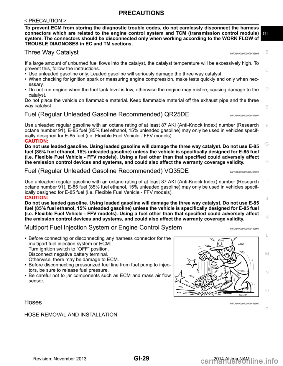
• Before connecting or disconnecti ng any harness connector for the
multiport fuel injection system or ECM:
Turn ignition switch to “OFF” position.
Disconnect negative battery terminal.
Otherwise, there may be damage to ECM.
• Before disconnecting pressurized fuel line from fuel pump to injec-
tors, be sure to release fuel pressure.
• Be careful not to jar components such as ECM and mass air flow sensor.
HosesINFOID:0000000009463000
HOSE REMOVAL AND INSTALLATION
SGI787
Revision: November 20132014 Altima NAMRevision: November 20132014 Altima NAM
Page 2592 of 4801

GW-12
< REMOVAL AND INSTALLATION >
WINDSHIELD GLASS
Removal and Installation
INFOID:0000000009463661
REMOVAL
1. Partially remove the headlining (front edge). Refer to INT-30, "Removal and Installation".
2. Remove inside mirror. Refer to MIR-19, "Removal and Installation"
.
3. Remove the cowl top cover. Refer to EXT-24, "Removal and Installation"
.
4. Remove roof side moldings (LH/RH). Refer to EXT-36, "Removal and Installation"
.
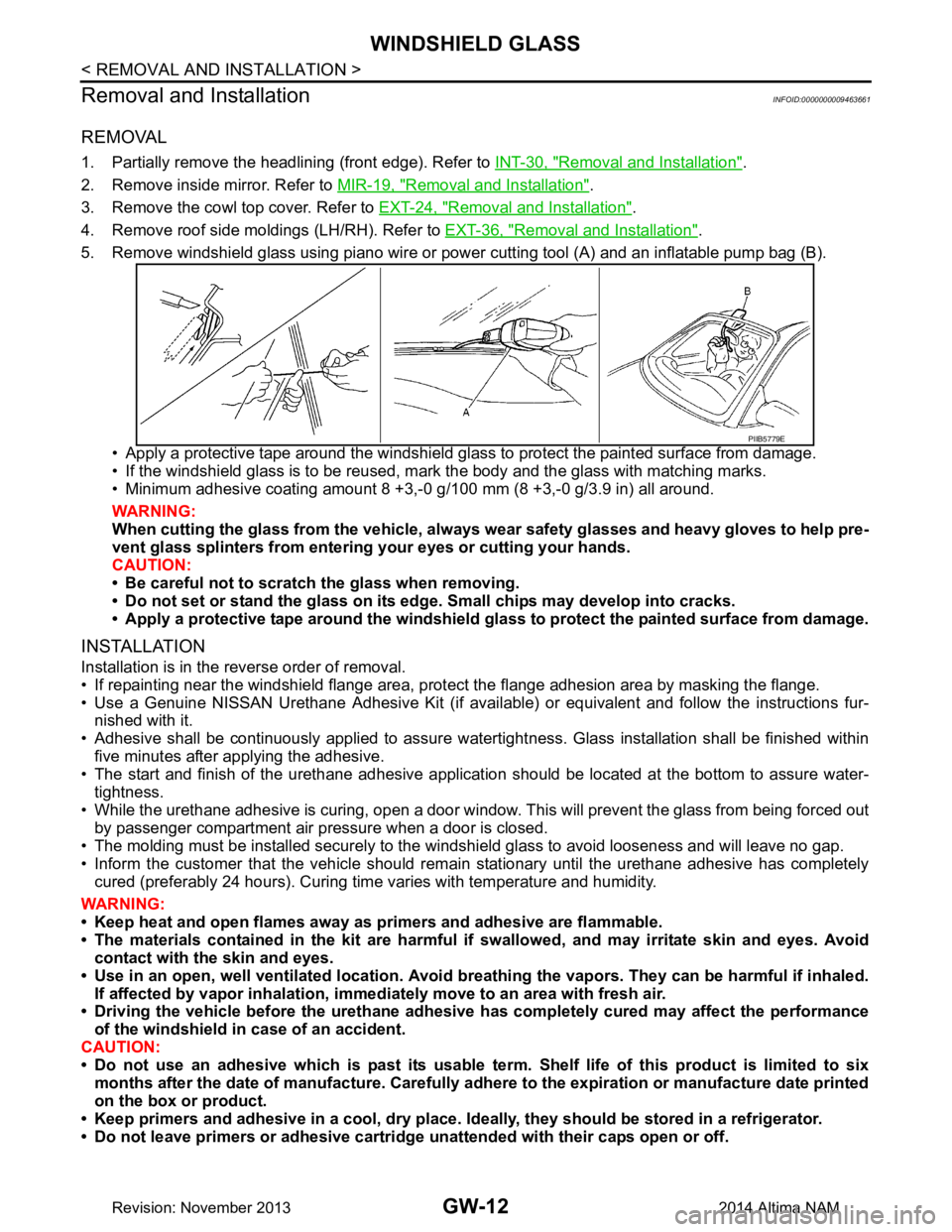
5. Remove windshield glass using piano wire or pow er cutting tool (A) and an inflatable pump bag (B).
• Apply a protective tape around the windshield gla ss to protect the painted surface from damage.
• If the windshield glass is to be reused, mark the body and the glass with matching marks.
• Minimum adhesive coating amount 8 +3,- 0 g/100 mm (8 +3,-0 g/3.9 in) all around.
WARNING:
When cutting the glass from the vehicle, always wear safety glasses and heavy gloves to help pre-
vent glass splinters from entering your eyes or cutting your hands.
CAUTION:
• Be careful not to scratch the glass when removing.
• Do not set or stand the glass on its ed ge. Small chips may develop into cracks.
• Apply a protective tape around the windshield glass to protect the painted surface from damage.
INSTALLATION
Installation is in the reverse order of removal.
• If repainting near the windshield flange area, pr otect the flange adhesion area by masking the flange.
• Use a Genuine NISSAN Urethane Adhesive Kit (if availabl e) or equivalent and follow the instructions fur-
nished with it.
• Adhesive shall be continuously applied to assure watert ightness. Glass installation shall be finished within
five minutes after applying the adhesive.
• The start and finish of the urethane adhesive application should be located at the bottom to assure water-
tightness.
• While the urethane adhesive is curing, open a door window . This will prevent the glass from being forced out
by passenger compartment air pressure when a door is closed.
• The molding must be installed securely to the windshield glass to avoid looseness and will leave no gap.
• Inform the customer that the vehicle should rema in stationary until the urethane adhesive has completely
cured (preferably 24 hours). Curing time varies with temperature and humidity.
WARNING:
• Keep heat and open flames away as primers and adhesive are flammable.
• The materials contained in the kit are harmful if swallowed, and may irritate skin and eyes. Avoid
contact with the skin and eyes.
• Use in an open, well ventilated location. Avoid br eathing the vapors. They can be harmful if inhaled.
If affected by vapor inhalation, imme diately move to an area with fresh air.
• Driving the vehicle before the urethane adhesive has completely cured may affect the performance
of the windshield in case of an accident.
CAUTION:
• Do not use an adhesive which is past its usable te rm. Shelf life of this product is limited to six
months after the date of manufacture. Carefully a dhere to the expiration or manufacture date printed
on the box or product.
• Keep primers and adhesive in a c ool, dry place. Ideally, they should be stored in a refrigerator.
• Do not leave primers or adhesive cartridge unattended with their caps open or off.
PIIB5779E
Revision: November 20132014 Altima NAM
Page 2604 of 4801

GW-24
< REMOVAL AND INSTALLATION >
SIDE WINDOW GLASS
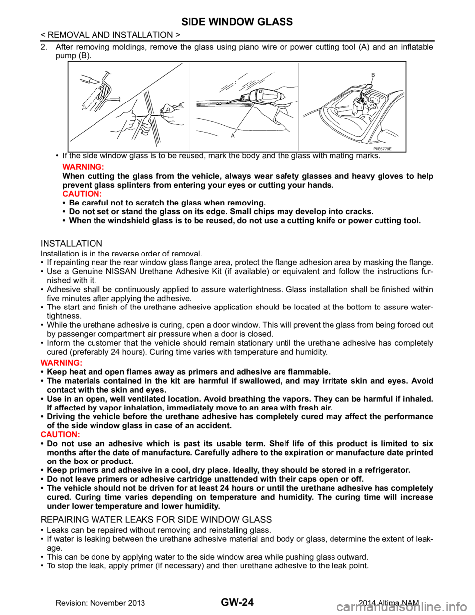
2. After removing moldings, remove the glass using piano wire or power cutting tool (A) and an inflatablepump (B).
• If the side window glass is to be reused, mark the body and the glass with mating marks. WARNING:
When cutting the glass from the vehicle, al ways wear safety glasses and heavy gloves to help
prevent glass splinters from entering your eyes or cutting your hands.
CAUTION:
• Be careful not to scratch the glass when removing.
• Do not set or stand the glass on its edge. Small chips may develop into cracks.
• When the windshield glass is to be reused, do not use a cutting knife or power cutting tool.
INSTALLATION
Installation is in the reverse order of removal.
• If repainting near the rear window glass flange area, protect the flange adhesion area by masking the flange.
• Use a Genuine NISSAN Urethane Adhesive Kit (if availabl e) or equivalent and follow the instructions fur-
nished with it.
• Adhesive shall be continuously applied to assure watert ightness. Glass installation shall be finished within
five minutes after applying the adhesive.
• The start and finish of the urethane adhesive application should be located at the bottom to assure water-
tightness.
• While the urethane adhesive is curing, open a door window . This will prevent the glass from being forced out
by passenger compartment air pressure when a door is closed.
• Inform the customer that the vehicle should rema in stationary until the urethane adhesive has completely
cured (preferably 24 hours). Curing time varies with temperature and humidity.
WARNING:
• Keep heat and open flames away as primers and adhesive are flammable.
• The materials contained in the kit are harmful if swallowed, and may irritate skin and eyes. Avoid
contact with the skin and eyes.
• Use in an open, well ventilated location. Avoid br eathing the vapors. They can be harmful if inhaled.
If affected by vapor inhalation, imme diately move to an area with fresh air.
• Driving the vehicle before the urethane adhesive has completely cured may affect the performance
of the side window gl ass in case of an accident.
CAUTION:
• Do not use an adhesive which is past its usable te rm. Shelf life of this product is limited to six
months after the date of manufacture. Carefully a dhere to the expiration or manufacture date printed
on the box or product.
• Keep primers and adhesive in a c ool, dry place. Ideally, they should be stored in a refrigerator.
• Do not leave primers or adhesive cartridge unattended with their caps open or off.
• The vehicle should not be driven for at least 24 hours or until the urethane adhesive has completely
cured. Curing time varies depe nding on temperature and humidity . The curing time will increase
under lower temperature and lower humidity.
REPAIRING WATER LEAKS FOR SIDE WINDOW GLASS
• Leaks can be repaired without removing and reinstalling glass.
• If water is leaking between the urethane adhesive material and body or glass, determine the extent of leak-
age.
• This can be done by applying water to the side window area while pushing glass outward.
• To stop the leak, apply primer (if necessary) and then urethane adhesive to the leak point.
PIIB5779E
Revision: November 20132014 Altima NAM
Page 2606 of 4801

GW-26
< REMOVAL AND INSTALLATION >
REAR WINDOW GLASS
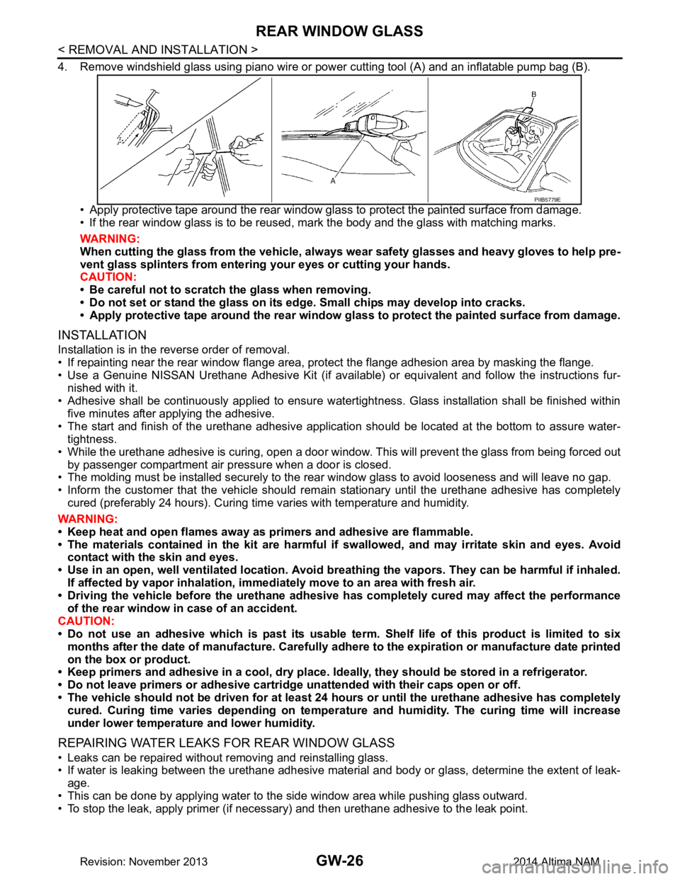
4. Remove windshield glass using piano wire or power cutting tool (A) and an inflatable pump bag (B).
• Apply protective tape around the rear window gla ss to protect the painted surface from damage.
• If the rear window glass is to be reused, mark the body and the glass with matching marks.
WARNING:
When cutting the glass from the vehicle, always wear safety glasses and heavy gloves to help pre-
vent glass splinters from entering your eyes or cutting your hands.
CAUTION:
• Be careful not to scratch the glass when removing.
• Do not set or stand the glass on its ed ge. Small chips may develop into cracks.
• Apply protective tape around th e rear window glass to protect the painted surface from damage.
INSTALLATION
Installation is in the reverse order of removal.
• If repainting near the rear window flange area, protect the flange adhesion area by masking the flange.
• Use a Genuine NISSAN Urethane Adhesive Kit (if availabl e) or equivalent and follow the instructions fur-
nished with it.
• Adhesive shall be continuously applied to ensure watert ightness. Glass installation shall be finished within
five minutes after applying the adhesive.
• The start and finish of the urethane adhesive application should be located at the bottom to assure water-
tightness.
• While the urethane adhesive is curing, open a door window . This will prevent the glass from being forced out
by passenger compartment air pressure when a door is closed.
• The molding must be installed securely to the rear window glass to avoid looseness and will leave no gap.
• Inform the customer that the vehicle should rema in stationary until the urethane adhesive has completely
cured (preferably 24 hours). Curing time varies with temperature and humidity.
WARNING:
• Keep heat and open flames away as primers and adhesive are flammable.
• The materials contained in the kit are harmful if swallowed, and may irritate skin and eyes. Avoid
contact with the skin and eyes.
• Use in an open, well ventilated location. Avoid br eathing the vapors. They can be harmful if inhaled.
If affected by vapor inhalation, imme diately move to an area with fresh air.
• Driving the vehicle before the urethane adhesive has completely cured may affect the performance
of the rear window in case of an accident.
CAUTION:
• Do not use an adhesive which is past its usable te rm. Shelf life of this product is limited to six
months after the date of manufacture. Carefully a dhere to the expiration or manufacture date printed
on the box or product.
• Keep primers and adhesive in a c ool, dry place. Ideally, they should be stored in a refrigerator.
• Do not leave primers or adhesive cartridge unattended with their caps open or off.
• The vehicle should not be driven for at least 24 hours or until the urethane adhesive has completely
cured. Curing time varies depe nding on temperature and humidity . The curing time will increase
under lower temperature and lower humidity.
REPAIRING WATER LEAKS FOR REAR WINDOW GLASS
• Leaks can be repaired without removing and reinstalling glass.
• If water is leaking between the urethane adhesive material and body or glass, determine the extent of leak-
age.
• This can be done by applying water to the side window area while pushing glass outward.
• To stop the leak, apply primer (if necessary) and then urethane adhesive to the leak point.
PIIB5779E
Revision: November 20132014 Altima NAM
Page 2607 of 4801

HA-1
VENTILATION, HEATER & AIR CONDITIONER
C
D E
F
G H
J
K L
M
SECTION HA
A
B
HA
N
O P
CONTENTS
HEATER & AIR CONDITIONING SYSTEM
PRECAUTION ................ ...............................3
PRECAUTIONS .............................................. .....3
Precaution for Supplemental Restraint System
(SRS) "AIR BAG" and "SEAT BELT PRE-TEN-
SIONER" ............................................................. ......
3
Precaution for Work ..................................................3
Precaution for Working with HFC-134a (R-134a) ......3
Contaminated Refrigerant .........................................4
Precaution for Leak Detection Dye ...........................4
Precaution for Refrigerant Connection ......................4
Precaution for Service Equipment ....................... ......7
PREPARATION ............................................9
PREPARATION .............................................. .....9
Special Service Tool ........................................... ......9
HFC-134a (R-134a) Service Tool and Equipment ......9
Commercial Service Tool ........................................11
SYSTEM DESCRIPTION .............................13
REFRIGERATION SYSTEM .......................... ....13
Refrigerant Cycle ................................................ ....13
Refrigerant System Protection ................................13
Component Part Location ................................... ....14
BASIC INSPECTION ...................................15
DIAGNOSIS AND REPAIR WORKFLOW ..... ....15
Workflow ............................................................. ....15
SYMPTOM DIAGNOSIS ..............................17
HEATER AND AIR CONDITIONING SYSTEM
SYMPTOMS ................................................... ....
17
Symptom Table ................................................... ....17
REFRIGERATION SYSTEM SYMPTOMS .........18
Trouble Diagnosis For Unusual Pressure ........... ....18
Symptom Table .......................................................18
NOISE .................................................................20
Symptom Table ................................................... ....20
PERIODIC MAINTENANCE ........................21
REFRIGERANT ................................ .................21
Description ........................................................... ....21
Leak Test .................................................................21
Recycle Refrigerant .................................................23
Charge Refrigerant ..................................................23
OIL .....................................................................25
Description ...............................................................25
Inspection ................................................................25
Perform Oil Return Operation ..................................25
Oil Adjusting Procedure for Components Replace-
ment Except Compressor ........................................
25
Oil Adjusting Procedure for Compressor Replace-
ment ..................................................................... ....
26
PERFORMANCE TEST ....................................28
Inspection ................................................................28
REMOVAL AND INSTALLATION ...............30
COMPRESSOR .................................................30
COMPRESSOR ........ ..................................................30
COMPRESSOR : Exploded Vi ew ............................30
COMPRESSOR : Removal an d Installation ............30
MAGNET CLUTCH ................................................ ....31
MAGNET CLUTCH : Removal and Installation .......31
COOLER PIPE AND HOSE ..............................34
Exploded View .........................................................34
LOW-PRESSURE FLEXIBLE HOSE ..................... ....34
LOW-PRESSURE FLEXIBLE HOSE : Removal
and Installation .................................................... ....
34
HIGH-PRESSURE FLEXIBLE HOSE ........................35
HIGH-PRESSURE FLEXIBLE HOSE : Removal
and Installation .................................................... ....
35
Revision: November 20132014 Altima NAM
Page 2608 of 4801

HA-2
LOW-PRESSURE PIPE ............................................35
LOW-PRESSURE PIPE : Removal and Installa-
tion ....................................................................... ...
35
HIGH-PRESSURE PIPE ......................................... ...36
HIGH-PRESSURE PIPE : Removal and Installa-
tion ....................................................................... ...
36
CONDENSER ....................................................38
Exploded View ..................................................... ...38
CONDENSER ......................................................... ...38
CONDENSER : Removal and Installation ..............38
LIQUID TANK ......................................................... ...38
LIQUID TANK : Removal and Installation ...............38
REFRIGERANT PRESSURE SENSOR ....................39
REFRIGERANT PRESSURE SENSOR : Remov-
al and Installation ................................................. ...
39
HEATING AND COOLING UNIT ASSEMBLY ...40
Exploded View ..................................................... ...40
HEATING AND COOLING UNIT ASSEMBLY ....... ...40
HEATING AND COOLING UNIT ASSEMBLY :
Removal and Installation .........................................
41
HEATER CORE ...................................................... ...41
HEATER CORE : Removal and Installation ............42
EVAPORATOR ....................................................... ...42
EVAPORATOR : Removal and Installation .............42
EXPANSION VALVE .............................................. ...42
EXPANSION VALVE : Removal and Installation
for Expansion Valve ............................................. ...
42
SERVICE DATA AND SPECIFICATIONS
(SDS) ............... ...........................................
43
SERVICE DATA AND SPECIFICATIONS
(SDS) .............................................................. ...
43
Service Data and Specification (SDS) ....................43
Revision: November 20132014 Altima NAM
Page 2610 of 4801

HA-4
< PRECAUTION >
PRECAUTIONS
• Use only specified oil for the HFC-134a (R-134a) A/C system and HFC-134a (R-134a) components. If
oil other than that specified is used , compressor failure is likely to occur.
• The specified HFC-134a (R-134a) oi l rapidly absorbs moisture from the atmosphere. The following
handling precautions must be observed:
- When removing refrigerant components from a vehicle, immediately cap (seal) the component to
minimize the entry of moisture from the atmosphere.
- When installing refrigerant co mponents to a vehicle, do not remove the caps (unseal) until just
before connecting the components . Connect all refrigerant loop components as quickly as possible
to minimize the entry of moisture into system.
- Only use the specified oil from a sealed container. Immediately reseal containers of oil. Without
proper sealing, oil will become moisture saturat ed and should not be used.
- Avoid breathing A/C refrigerant and oil vapor or mist. Exposure may irritate eyes, nose and throat.
Remove HFC-134a (R-134a) from the A/C system usin g certified service equipment meeting require-
ments of SAE J2210 [HFC-134a (R-134a) recycling equipment], or J2209 [HFC-134a (R-134a) recy-
cling equipment], If accidental system discharge occurs, ventilate work area before resuming
service. Additional health and safety information may be obtain ed from refrigerant and oil manufac-
turers.
- Do not allow A/C oil to come in contact with styrofoam parts. Damage may result.
Contaminated RefrigerantINFOID:0000000009463911
If a refrigerant other than pure HFC-134a (R-134a) is identified in a vehicle, your options are:
• Explain to the customer that environmental regulations prohibit the release of contaminated refrigerant into
the atmosphere.
• Explain that recovery of the contaminated refri gerant could damage your service equipment and refrigerant
supply.
• Suggest the customer return the vehicle to the locati on of previous service where the contamination may
have occurred.
• If you choose to perform the repair, recover the refrigerant using only dedicated equipment and contain-
ers. Do not recover contamin ated refrigerant into your existing service equipment. If your facility does
not have dedicated recovery equipment, you may contact a local refrigerant product retailer for available ser-
vice. This refrigerant must be disposed of in acco rdance with all federal and local regulations. In addition,
replacement of all refrigerant system components on the vehicle is recommended.
• If the vehicle is within the warranty period, the air conditioner warranty is void. Please contact NISSAN Cus-
tomer Affairs for further assistance.
Precaution for Leak Detection DyeINFOID:0000000009463912
• The A/C system contains a fluorescent leak detection dye used for locating refrigerant leaks. An ultraviolet
(UV) lamp is required to illuminate the dye when inspecting for leaks.
• Always wear fluorescence enhancing UV safety goggles to protect your eyes and enhance the visibility of
the fluorescent dye.
• A compressor shaft seal should not be repaired because of dye seepage. The compressor shaft seal should only be repaired after confirming the leak with an electronic refrigerant leak detector (J-41995).
• Always remove any dye from the leak area after repairs are complete to avoid a misdiagnosis during a future
service.
• Do not allow dye to come into contact with painted body panels or interior components. If dye is spilled,
clean immediately with the approved dye cleaner. Fluoresc ent dye left on a surface for an extended period of
time cannot be removed .
• Do not spray the fluorescent dye cleaning agent on hot surfaces (engine exhaust manifold, etc.).
• Do not use more than one refrigerant dye bottle (1/4 ounce / 7.4 cc) per A/C system.
• Leak detection dyes for HFC-134a (R-134a) and HC-12 (R- 12) A/C systems are different. Do not use HFC-
134a (R-134a) leak detection dye in R-12 A/C systems or HC-12 (R-12) leak detection dye in HFC-134a (R-
134a) A/C systems or A/C system damage may result.
• The fluorescent properties of the dye will remain for ov er three (3) years unless a compressor failure occurs.
Precaution for Refrigerant ConnectionINFOID:0000000009463913
A new type refrigerant connection has been introduced to al l refrigerant lines except the following locations.
• Expansion valve to cooling unit
• Evaporator pipes to evaporator (inside cooling unit)
• Refrigerant pressure sensor
Revision: November 20132014 Altima NAM