2014 NISSAN TEANA ECU
[x] Cancel search: ECUPage 3280 of 4801

MWI
COMBINATION METERMWI-25
< ECU DIAGNOSIS INFORMATION >
C
D E
F
G H
I
J
K L
M B
A
O P
4
(R) Ground Steering switch input 2 — — — —
5
(P) Ground ACC — Ignition
switch
ON Ignition switch ACC or ON
power supply Battery voltage
6
(G) Ground Security signal Input Ignition
switch
ON Security indicator ON 0 V
Security indicator OFF 12 V
7
(R) Ground Air bag signal Input Ignition
switch
ON Air bag warning lamp
ON —
Air bag warning lamp
OFF —
8
(W) Ground
Passenger seat belt warn-
ing signal InputIgnition
switch
ON Fastened 12 V
Unfastened 0 V
9
(V) Ground Seat belt buckle switch sig-
nal (driver seat) InputIgnition
switch
ON Fastened 12 V
Unfastened 0 V
11
(R) Ground Alternator signal Input Ignition
switch
ON Charge warning lamp ON 2 V
Charge warning lamp OFF Battery voltage
12
(G) Ground Parking brake switch signal Input Ignition
switch
ON Parking brake applied 0 V
Parking brake released 12 V
18
(BR) Ground AC PD cut Input Ignition
switch
ON Signal ON 0 V
Signal OFF 5 V
21
(BR) —Ignition — Ignition
switch
ON or
START —12 V
22
(G) — Battery power supply — Ignition
switch
OFF —Battery voltage
23
(GR) Ground Illumination control output
signal —Ignition
switch
ON —0 V
24
(W) Ground Steering switch ground — Ignition
switch
ON —0 V
25
(BR) Ground Brake fluid level switch Input Ignition
switch
ON Brake fluid level low 0 V
Brake fluid level normal Battery voltage
26
(R) Ground Fuel level sensor ground — Ignition
switch
ON —0 V
27
(W) Ground Fuel level sensor signal — — — —
30
(L) Ground Ambient sensor signal
(without auto A/C) InputIgnition
switch
ON —
0-5 V
(based on ambient temperature)
Te r m i n a l N o .
(Wire color) Description
ConditionVa l u e
(Approx.)
+ – Signal name Input/
Output
Revision: November 20132014 Altima NAMRevision: November 20132014 Altima NAM
Page 3281 of 4801

MWI-26
< ECU DIAGNOSIS INFORMATION >
COMBINATION METER
31
(W) Ground Ambient sensor ground
(without auto A/C) InputIgnition
switch
ON —0 V
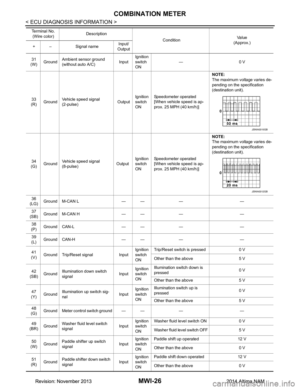
33
(R) Ground Vehicle speed signal
(2-pulse) OutputIgnition
switch
ON Speedometer operated
[When vehicle speed is ap-
prox. 25 MPH (40 km/h)] NOTE:
The maximum voltage varies de-
pending on the specification
(destination unit).
34
(G) Ground Vehicle speed signal
(8-pulse) OutputIgnition
switch
ON Speedometer operated
[When vehicle speed is ap-
prox. 25 MPH (40 km/h)] NOTE:
The maximum voltage varies de-
pending on the specification
(destination unit).
36
(LG) Ground M-CAN L — — — —
37
(SB) Ground M-CAN H — — — —
38
(P) Ground CAN-L — — — —
39
(L) Ground CAN-H — — — —
41
(V) Ground Trip/Reset signal Input Ignition
switch
ON Trip/Reset switch is pressed 0 V
Other than the above 5 V
42
(SB) Ground Illumination down switch
signal InputIgnition
switch
ON Illumination switch down is
pressed 0 V
Other than the above 5 V
47
(Y) Ground
Illumination up switch sig-
nal InputIgnition
switch
ON Illumination switch up is
pressed 0 V
Other than the above 5 V
48
(G) Ground Meter control switch ground — — — —
49
(BR) Ground Washer fluid level switch
signal InputIgnition
switch
ON Washer fluid level switch ON 0 V
Washer fluid level switch OFF 5 V
50
(W) Ground
Paddle shifter up switch
signal InputIgnition
switch
ON Paddle shift up operated 12 V
Other than the above 0 V
51
(R) Ground Paddle shifter down switch
signal InputIgnition
switch
ON Paddle shift down operated 12 V
Other than the above 0 V
Te r m i n a l N o .
(Wire color) Description
ConditionVa l u e
(Approx.)
+ – Signal name Input/
Output
JSNIA0015GB
JSNIA0012GB
Revision: November 20132014 Altima NAMRevision: November 20132014 Altima NAM
Page 3282 of 4801

MWI
COMBINATION METERMWI-27
< ECU DIAGNOSIS INFORMATION >
C
D E
F
G H
I
J
K L
M B
A
O PFail-SafeINFOID:0000000009461695
FA I L - S A F E
The combination meter activates the fail-safe contro l if CAN communication with each unit is malfunctioning.
DTC IndexINFOID:0000000009461696
52
(P) Ground O/D OFF/SPORT switch Input Ignition
switch
ON O/D OFF switch pressed 0 V
Other than the above 5 V
Te r m i n a l N o .
(Wire color) Description
ConditionVa l u e
(Approx.)
+ – Signal name Input/
Output
Function Specifications
Speedometer Reset to zero by suspending communication.
Tachometer
Engine coolant temperature gauge
Illumination control When suspending communication, changes to nighttime mode.
Information display Odo/trip meter An indicated value is maintained at communications blackout.
Shift position indicator The display turns OFF by suspending communication.
Warning messages The display turns OFF by suspending communication.
Buzzer The buzzer turns OFF by suspending communication.
Warning lamp/indicator lamp ABS warning lamp
The lamp turns ON by suspending communication.
O/D OFF indicator lamp
Slip indicator lamp
Brake warning lamp
Malfunction indicator lamp
VDC OFF indicator lamp
EPS warning lamp
Low tire pressure warning lamp The lamp blinking caused by suspending communication.
High beam indicator lamp
The lamp turns OFF by suspending communication.
Turn signal indicator lamp
Master warning lamp
Front lamp indicator lamp
Lane departure warning
Tail lamp indicator lamp
Air bag warning lamp
The lamp turns off when disconnected.
Charge warning lamp
Seat belt warning lamp
Security indicator lamp
Display contents of CONSULT Diagnostic item is detected when... Refer to
CAN COMM CIRCUIT
[U1000] When combination meter is not transmitting or receiving CAN communication signal for 2
seconds or more. MWI-53
CONTROL UNIT (CAN)
[U1010] When detecting error during the initial diagnosis of the CAN controller of combination
meter. MWI-54
Revision: November 20132014 Altima NAMRevision: November 20132014 Altima NAM
Page 3283 of 4801
![NISSAN TEANA 2014 Service Manual
MWI-28
< ECU DIAGNOSIS INFORMATION >
COMBINATION METER
VEHICLE SPEED CIRC
[B2205] The abnormal vehicl
e speed signal is input from the ABS actuator and electric unit (control
unit) for 2 seconds NISSAN TEANA 2014 Service Manual
MWI-28
< ECU DIAGNOSIS INFORMATION >
COMBINATION METER
VEHICLE SPEED CIRC
[B2205] The abnormal vehicl
e speed signal is input from the ABS actuator and electric unit (control
unit) for 2 seconds](/manual-img/5/57390/w960_57390-3282.png)
MWI-28
< ECU DIAGNOSIS INFORMATION >
COMBINATION METER
VEHICLE SPEED CIRC
[B2205] The abnormal vehicl
e speed signal is input from the ABS actuator and electric unit (control
unit) for 2 seconds or more. MWI-55
TACHO METER
[B2267] If ECM continuously transmits abnormal engine speed signals for 2 seconds or more.
MWI-56
WATER TEMP METER
[B2268] If ECM continuously transmits abnormal engine coolant temperature signals for 60 sec-
onds or more. MWI-57
Display contents of CONSULT Diagnostic item is detected when... Refer to
Revision: November 20132014 Altima NAMRevision: November 20132014 Altima NAM
Page 3284 of 4801

MWI
BCM, IPDM E/RMWI-29
< ECU DIAGNOSIS INFORMATION >
C
D E
F
G H
I
J
K L
M B
A
O P
BCM, IPDM E/R
List of ECU ReferenceINFOID:0000000009461697
ECU Reference
BCM BCS-31, "Reference Value"
BCS-50, "Fail Safe"
BCS-50, "DTC Inspection Priority Chart"
BCS-52, "DTC Index"
IPDM E/R
PCS-12, "Reference Value"PCS-19, "Fail Safe"
PCS-20, "DTC Index"
Revision: November 20132014 Altima NAMRevision: November 20132014 Altima NAM
Page 3342 of 4801

PB-4
< BASIC INSPECTION >
PARKING BRAKE SYSTEM
BASIC INSPECTION
PARKING BRAKE SYSTEM
InspectionINFOID:0000000009462912
PEDAL STROKE
1. Operate parking brake pedal with a force of 196 N (20.0 kg-f, 44.1 lb-f), make sure pedal stroke is within
the specified number of notches. (Check it by listening and counting ratchet clicks.)
2. When brake warning lamp turns ON, check that the pedal stroke is within the specified number of notches. (Check it by listening to the clicks of the ratchet.)
INSPECT COMPONENTS
• Make sure that the mounting conditions (loosenes s, backlash, etc.) of each component are normal.
• Check the following:
- Device assembly for bend, damage and cracks. Replace if necessary.
- Cables and equalizer for wear and damage. Replace if necessary.
- Parking brake switch. Replace if necessary.
AdjustmentINFOID:0000000009462913
ADJUSTMENT
1. Remove rear wheel and tire using power tool. Refer to WT-55, "Adjustment".
2. Insert a deep socket wrench onto adjusting nut. Rotate adjusting nut to fully loosen cable, and then release parking brake pedal.
3. Secure both disc rotors to hubs using wheel nuts so as not to tilt the disc rotors.
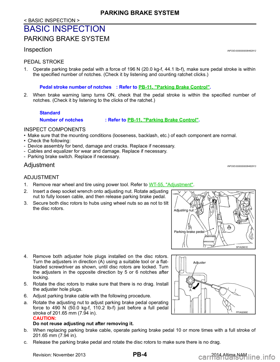
4. Remove both adjuster hole plugs installed on the disc rotors. Turn the adjusters in direction (A) using a suitable tool or a flat-
bladed screwdriver as shown, until disc rotors are locked. Turn
the adjusters in the opposite direction by 5 or 6 notches after
locking.
5. Rotate the disc rotors to make sure that there is no drag. Install the adjuster hole plugs.
6. Adjust parking brake cable with the following procedure.
a. Rotate the adjusting nut to adjust parking brake pedal operating force to 490 N (50.0 kg-f, 110.2 lb-f) just before a full pedal
stroke of 201.65 mm (7.94 in).
CAUTION:
Do not reuse adjusting nut after removing it.
b. When replacing parking brake cable, operate parking brake pedal 10 or more times with a full stroke of 201.65 mm (7.94 in).
c. Release the parking brake pedal and rotate the disc rotors to make sure there is no drag. Pedal stroke number of notches : Refer to
PB-11, "Parking Brake Control"
.
Standard
Number of notches : Refer to PB-11, "Parking Brake Control"
.
SFIA2961E
PFIA0295E
Revision: November 20132014 Altima NAM
Page 3347 of 4801

PARKING BRAKE SHOEPB-9
< REMOVAL AND INSTALLATION >
C
D E
G H
I
J
K L
M A
B
PB
N
O P
PARKING BRAKE SHOE
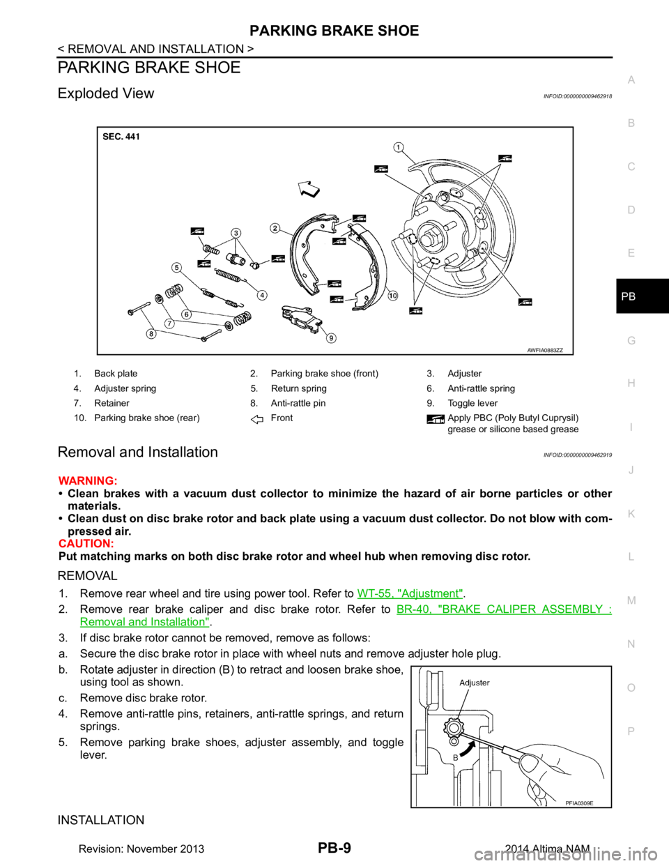
Exploded ViewINFOID:0000000009462918
Removal and InstallationINFOID:0000000009462919
WARNING:
• Clean brakes with a vacuum dust co llector to minimize the hazard of air borne particles or other
materials.
• Clean dust on disc brake rotor and back plate usin g a vacuum dust collector. Do not blow with com-
pressed air.
CAUTION:
Put matching marks on both disc brake rotor and wheel hub when removing disc rotor.
REMOVAL
1. Remove rear wheel and tire using power tool. Refer to WT-55, "Adjustment".
2. Remove rear brake caliper and disc brake rotor. Refer to BR-40, "BRAKE CALIPER ASSEMBLY :
Removal and Installation".
3. If disc brake rotor cannot be removed, remove as follows:
a. Secure the disc brake rotor in place with wheel nuts and remove adjuster hole plug.
b. Rotate adjuster in direction (B) to retract and loosen brake shoe, using tool as shown.
c. Remove disc brake rotor.
4. Remove anti-rattle pins, retainers, anti-rattle springs, and return springs.
5. Remove parking brake shoes, adjuster assembly, and toggle lever.
INSTALLATION
1. Back plate 2. Parking brake shoe (front) 3. Adjuster
4. Adjuster spring 5. Return spring 6. Anti-rattle spring
7. Retainer 8. Anti-rattle pin 9. Toggle lever
10. Parking brake shoe (rear) Front Apply PBC (Poly Butyl Cuprysil) grease or silicone based grease
AWFIA0883ZZ
PFIA0309E
Revision: November 20132014 Altima NAM
Page 3350 of 4801

PCS
PCS-1
ELECTRICAL & POWER CONTROL
C
D E
F
G H
I
J
K L
B
SECTION PCS
A
O P
N
CONTENTS
POWER CONTROL SYSTEM
IPDM E/R
PRECAUTION ................ ...............................
3
PRECAUTIONS .............................................. .....3
Precaution for Supplemental Restraint System
(SRS) "AIR BAG" and "SEAT BELT PRE-TEN-
SIONER" ............................................................. ......
3
Precaution for Procedure without Cowl Top Cover ......3
SYSTEM DESCRIPTION ..............................4
COMPONENT PARTS ................................... .....4
Component Parts Location .................................. ......4
SYSTEM ..............................................................5
RELAY CONTROL SYSTEM ................................ ......5
RELAY CONTROL SYSTEM : System Diagram ......5
RELAY CONTROL SYSTEM : System Descrip-
tion ...................................................................... ......
6
POWER CONSUMPTION CONTROL SYSTEM ... ......6
POWER CONSUMPTION CONTROL SYSTEM :
System Diagram .................................................. ......
7
POWER CONSUMPTION CONTROL SYSTEM :
System Description ............................................. ......
7
DIAGNOSIS SYSTEM (IPDM E/R) ......................8
Diagnosis Description ......................................... ......8
CONSULT Function (IPDM E/R) ...............................9
ECU DIAGNOSIS INFORMATION ..............12
IPDM E/R (INTELLIGENT POWER DISTRI-
BUTION MODULE ENGINE ROOM) ............. ....
12
Reference Value ................................................. ....12
Fail Safe .................................................................19
DTC Index ..............................................................20
WIRING DIAGRAM ......................................21
IPDM E/R (INTELLIGENT POWER DISTRI-
BUTION MODULE ENGINE ROOM) ................
21
Wiring Diagram .................................................... ....21
DTC/CIRCUIT DIAGNOSIS .........................27
U1000 CAN COMM CIRCUIT ...........................27
Description ........................................................... ....27
DTC Logic ................................................................27
Diagnosis Procedure ...............................................27
U1010 CONTROL UNIT (CAN) .........................28
DTC Logic ................................................................28
Diagnosis Procedure ...............................................28
B2098 IGNITION RELAY ON STUCK ..............29
DTC Logic ................................................................29
Diagnosis Procedure ...............................................29
B2099 IGNITION RELAY OFF STUCK ............30
DTC Logic ................................................................30
Diagnosis Procedure ...............................................30
POWER SUPPLY AND GROUND CIRCUIT ....31
Diagnosis Procedure ...............................................31
REMOVAL AND INSTALLATION ...............32
IPDM E/R (INTELLIGENT POWER DISTRI-
BUTION MODULE ENGINE ROOM) ................
32
Removal and Installation ..................................... ....32
POWER DISTRIBUTION SYSTEM
PRECAUTION ...... ........................................
33
PRECAUTIONS .................................................33
Precaution for Supplemental Restraint System
(SRS) "AIR BAG" and "SEAT BELT PRE-TEN-
SIONER" ............................................................. ....
33
Precaution for Work .................................................33
PREPARATION ...........................................34
Revision: November 20132014 Altima NAMRevision: November 20132014 Altima NAM