2014 NISSAN TEANA ECU
[x] Cancel search: ECUPage 3244 of 4801

MIR-14
< SYMPTOM DIAGNOSIS >
SQUEAK AND RATTLE TROUBLE DIAGNOSES
If possible, drive the vehicle with the customer until the noise is duplicated. Note any additional information on
the Diagnostic Worksheet regarding the conditions or lo cation of the noise. This information can be used to
duplicate the same conditions when you confirm the repair.
If the noise can be duplicated easily during the test drive, to help identify the source of the noise, try to dupli-
cate the noise with the vehicle stopped by doing one or all of the following:
1) Close a door.
2) Tap or push/pull around the area where the noise appears to be coming from.
3) Rev the engine.
4) Use a floor jack to recreate vehicle “twist”.
5) At idle, apply engine load (electrical load, half-clutch on M/T model, drive position on CVT and A/T models).
6) Raise the vehicle on a hoist and hit a tire with a rubber hammer.
• Drive the vehicle and attempt to duplicate the conditions the customer states exist when the noise occurs.
• If it is difficult to duplicate the noise, drive the v ehicle slowly on an undulating or rough road to stress the
vehicle body.
CHECK RELATED SERVICE BULLETINS
After verifying the customer concern or symptom, chec k ASIST for Technical Service Bulletins (TSBs) related
to that concern or symptom.
If a TSB relates to the symptom, follo w the procedure to repair the noise.
LOCATE THE NOISE AND IDENTIFY THE ROOT CAUSE
1. Narrow down the noise to a general area. To help pi npoint the source of the noise, use a listening tool
(Chassis Ear: J-39570, Engine Ear: J-39565 and mechanic's stethoscope).
2. Narrow down the noise to a more specific area and identify the cause of the noise by:
• removing the components in the area that you suspect the noise is coming from. Do not use too much force when removing clips and fasteners, otherwise clips and fasteners can be
broken or lost during the repair, resulting in the creation of new noise.
• tapping or pushing/pulling the component that you suspect is causing the noise.
Do not tap or push/pull the component with excessive force, otherwise the noise will be eliminated only
temporarily.
• feeling for a vibration with your hand by touching the component(s) that you suspect is (are) causing the
noise.
• placing a piece of paper between components that you suspect are causing the noise.
• looking for loose components and contact marks. Refer to MIR-14, "Generic Squeak and Rattle Troubleshooting"
.
REPAIR THE CAUSE
• If the cause is a loose component, tighten the component securely.
• If the cause is insufficient clearance between components:
- separate components by repositioning or loos ening and retightening the component, if possible.
- insulate components with a suitable insulator such as urethane pads, foam blocks, felt cloth tape or urethane
tape. A NISSAN Squeak and Rattle Kit (J-50397) is av ailable through your authorized NISSAN Parts Depart-
ment.
CAUTION:
Do not use excessive force as many components are constructed of plastic and may be damaged.
NOTE:
• Always check with the Parts Department for the latest parts information.
• The materials contained in the NISSAN Squeak and Rattle Kit (J-50397) are listed on the inside cover of the
kit; and can each be ordered separately as needed.
• The following materials not found in the kit can also be used to repair squeaks and rattles.
- SILICONE GREASE: Use instead of UHMW tape that will be visible or does not fit. The silicone grease will
only last a few months.
- SILICONE SPRAY: Use when grease cannot be applied.
- DUCT TAPE: Use to eliminate movement.
CONFIRM THE REPAIR
Confirm that the cause of a noise is repaired by test driving the vehicle. Operate the vehicle under the same
conditions as when the noise originally occurred. Refer to the notes on the Diagnostic Worksheet.
Generic Squeak and Rattle TroubleshootingINFOID:0000000009895303
Refer to Table of Contents for specific component removal and installation information.
Revision: November 20132014 Altima NAMRevision: November 20132014 Altima NAM
Page 3246 of 4801

MIR-16
< SYMPTOM DIAGNOSIS >
SQUEAK AND RATTLE TROUBLE DIAGNOSES
1. Loose harness or harness connectors.
2. Front console map/reading lamp lens loose.
3. Loose screws at console attachment points.
SEATS
When isolating seat noise it's important to note the pos ition the seat is in and the load placed on the seat when
the noise is present. These conditions should be dupl icated when verifying and isolating the cause of the
noise.
Cause of seat noise include:
1. Headrest rods and holder
2. A squeak between the seat pad cushion and frame
3. The rear seatback lock and bracket
These noises can be isolated by moving or pressing on the suspected components while duplicating the con-
ditions under which the noise occurs. Most of thes e incidents can be repaired by repositioning the component
or applying urethane tape to the contact area.
UNDERHOOD
Some interior noise may be caused by components under the hood or on the engine wall. The noise is then
transmitted into the passenger compartment.
Causes of transmitted underhood noise include:
1. Any component installed to the engine wall
2. Components that pass through the engine wall
3. Engine wall mounts and connectors
4. Loose radiator installation pins
5. Hood bumpers out of adjustment
6. Hood striker out of adjustment
These noises can be difficult to isolate since they cannot be reached from the interior of the vehicle. The best
method is to secure, move or insulate one component at a time and test drive the vehicle. Also, engine rpm or
load can be changed to isolate the noise. Repairs can usually be made by moving, adjusting, securing, or
insulating the component causing the noise.
Revision: November 20132014 Altima NAMRevision: November 20132014 Altima NAM
Page 3253 of 4801

DOOR MIRROR REAR FINISHERMIR-23
< REMOVAL AND INSTALLATION >
C
D E
F
G H
I
J
K
M A
B
MIR
N
O P
DOOR MIRROR REAR FINISHER
Removal and InstallationINFOID:0000000009463534
REMOVAL
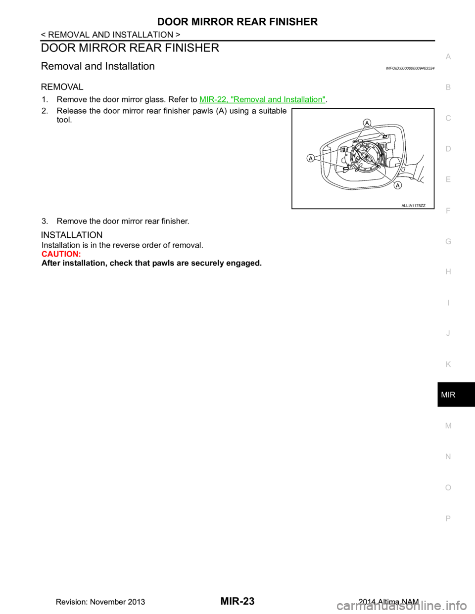
1. Remove the door mirror glass. Refer to MIR-22, "Removal and Installation".
2. Release the door mirror rear finisher pawls (A) using a suitable tool.
3. Remove the door mirror rear finisher.
INSTALLATION
Installation is in the reverse order of removal.
CAUTION:
After installation, check that pawls are securely engaged.
ALLIA1175ZZ
Revision: November 20132014 Altima NAMRevision: November 20132014 Altima NAM
Page 3256 of 4801

MWI
MWI-1
DRIVER INFORMATION & MULTIMEDIA
C
D E
F
G H
I
J
K L
M B
SECTION MWI
A
O P
CONTENTS
METER, WARNING LAMP & INDICATOR
PRECAUTION ................ ...............................4
PRECAUTIONS .............................................. .....4
Precaution for Supplemental Restraint System
(SRS) "AIR BAG" and "SEAT BELT PRE-TEN-
SIONER" ............................................................. ......
4
PREPARATION ............................................5
PREPARATION .............................................. .....5
Special Service Tools .......................................... ......5
Commercial Service Tools ........................................5
SYSTEM DESCRIPTION ..............................6
COMPONENT PARTS ................................... .....6
METER SYSTEM .........................................................6
METER SYSTEM : Compo nent Parts Location ........6
METER SYSTEM : Component Description ....... ......7
SYSTEM ..............................................................9
METER SYSTEM .........................................................9
METER SYSTEM : System Diagram ........................9
METER SYSTEM : System Description ....................9
METER SYSTEM : Arrangem ent of Combination
Meter ................................................................... ....
10
METER SYSTEM : Fail-Safe ..................................10
SPEEDOMETER ................ ........................................11
SPEEDOMETER : System Diagram ................... ....11
SPEEDOMETER : System Description ...................11
TACHOMETER ...................................................... ....11
TACHOMETER : System Diagram .........................12
TACHOMETER : System De scription .....................12
ENGINE COOLANT TEMPERATURE GAUGE .... ....12
ENGINE COOLANT TEMPERATURE GAUGE :
System Diagram .................................................. ....
12
ENGINE COOLANT TEMPERATURE GAUGE :
System Description ............................................. ....
12
FUEL GAUGE ........................................................ ....12
FUEL GAUGE : System Diagram ............................12
FUEL GAUGE : System Description .......................12
MASTER WARNING LAMP ................................... ....12
MASTER WARNING LAMP : System Diagram .......13
MASTER WARNING LAMP : System Description ....13
METER ILLUMINATION CONTROL ..................... ....13
METER ILLUMINATION CONTROL : System Di-
agram .................................................................. ....
13
METER ILLUMINATION CONTROL : System De-
scription ............................................................... ....
13
METER EFFECT FUNCTION ................................ ....13
METER EFFECT FUNCTION : System Diagram ....14
METER EFFECT FUNCTION : System Descrip-
tion ....................................................................... ....
14
INFORMATION DISPLAY ...................................... ....15
INFORMATION DISPLAY : System Diagram ..........15
INFORMATION DISPLAY : System Description .....15
COMPASS ............................................................. ....16
COMPASS : Description ..........................................16
DIAGNOSIS SYSTEM (METER) .......................18
Description ........................................................... ....18
CONSULT Function (METER/M&A) ........................18
ECU DIAGNOSIS INFORMATION ..............22
COMBINATION METER ...................................22
Reference Value .................................................. ....22
Fail-Safe ..................................................................27
DTC Index ...............................................................27
BCM, IPDM E/R .................................................29
List of ECU Reference .............................................29
WIRING DIAGRAM ......................................30
COMPASS .........................................................30
Revision: November 20132014 Altima NAMRevision: November 20132014 Altima NAM
Page 3266 of 4801

MWI
SYSTEMMWI-11
< SYSTEM DESCRIPTION >
C
D E
F
G H
I
J
K L
M B
A
O P
SPEEDOMETER
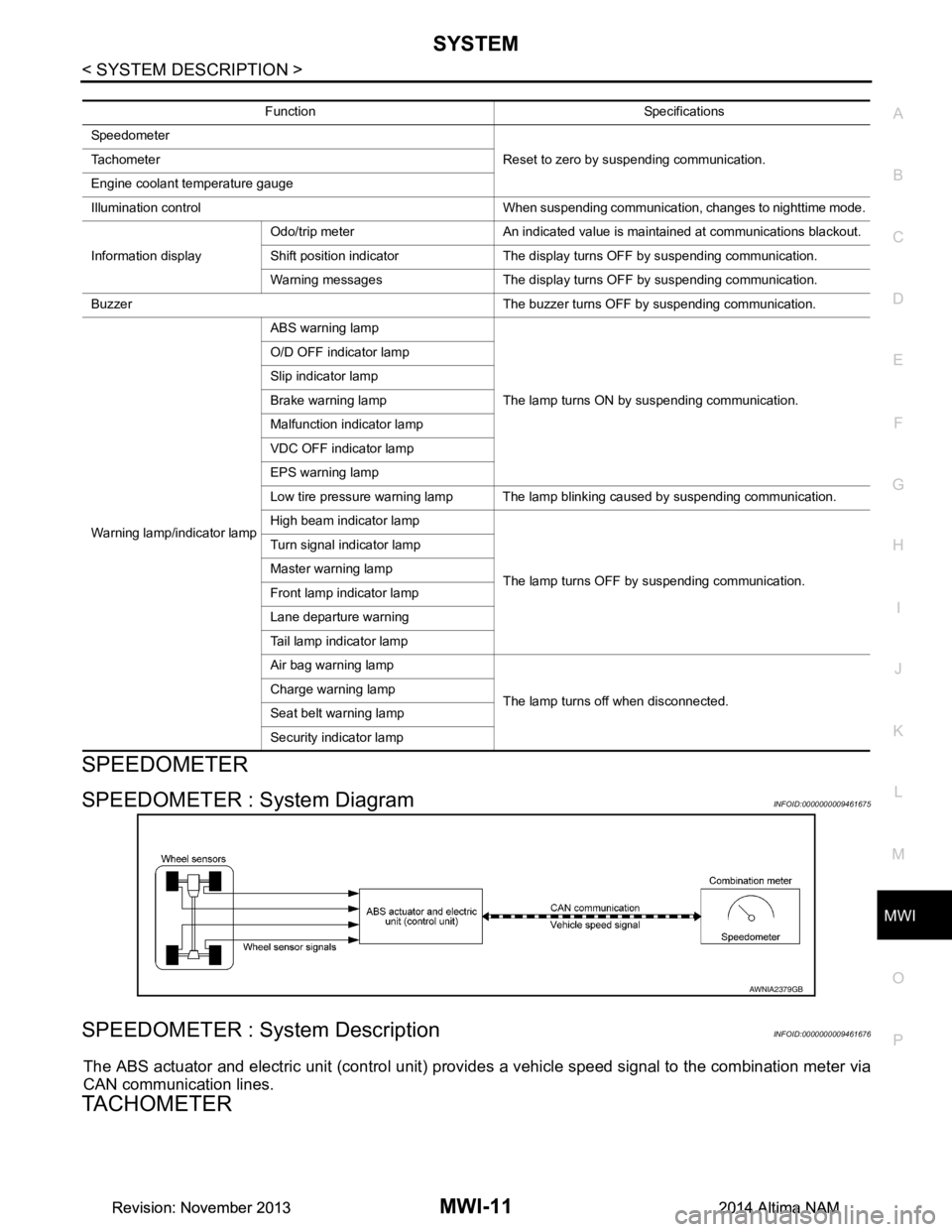
SPEEDOMETER : System DiagramINFOID:0000000009461675
SPEEDOMETER : System DescriptionINFOID:0000000009461676
The ABS actuator and electric unit (control unit) provi des a vehicle speed signal to the combination meter via
CAN communication lines.
TACHOMETER
Function Specifications
Speedometer Reset to zero by suspending communication.
Tachometer
Engine coolant temperature gauge
Illumination control When suspending communication, changes to nighttime mode.
Information display Odo/trip meter An indicated value is maintained at communications blackout.
Shift position indicator The display turns OFF by suspending communication.
Warning messages The display turns OFF by suspending communication.
Buzzer The buzzer turns OFF by suspending communication.
Warning lamp/indicator lamp ABS warning lamp
The lamp turns ON by suspending communication.
O/D OFF indicator lamp
Slip indicator lamp
Brake warning lamp
Malfunction indicator lamp
VDC OFF indicator lamp
EPS warning lamp
Low tire pressure warning lamp The lamp blinking caused by suspending communication.
High beam indicator lamp
The lamp turns OFF by suspending communication.
Turn signal indicator lamp
Master warning lamp
Front lamp indicator lamp
Lane departure warning
Tail lamp indicator lamp
Air bag warning lamp
The lamp turns off when disconnected.
Charge warning lamp
Seat belt warning lamp
Security indicator lamp
AWNIA2379GB
Revision: November 20132014 Altima NAMRevision: November 20132014 Altima NAM
Page 3277 of 4801

MWI-22
< ECU DIAGNOSIS INFORMATION >
COMBINATION METER
ECU DIAGNOSIS INFORMATION
COMBINATION METER
Reference ValueINFOID:0000000009461694
VALUES ON THE DIAGNOSIS TOOL
Monitor Item Condition Value/Status
SPEED METER
[mph or km/h] Ignition switch ON While driving
Input value of vehicle speed signal
(CAN communication signal)
SPEED OUTPUT
[mph or km/h] Ignition switch ON While driving Output value of vehicle speed sig-
nal (CAN communication signal)
ODO OUTPUT
[mph or km/h] Ignition switch ON — Output value of odometer signal
(CAN communication signal)
TACHO METER
[rpm] Ignition switch ON Engine running
Input value of engine speed signal
(CAN communication signal)
FUEL METER
[L] Ignition switch ON — Input value of fuel level sensor sig-
nal
W TEMP METER
[ ° F] or [ °C] Ignition switch ON — Input value of engine coolant tem-
perature signal (CAN communica-
tion signal)
ABS W/L Ignition switch ON ABS warning lamp ON On
ABS warning lamp OFF Off
VDC/TCS IND Ignition switch ON VDC OFF indica
tor lamp ON On
VDC OFF indicato r lamp OFF Off
SLIP IND Ignition switch ON VDC warning lamp ON On
VDC warning lamp OFF Off
BRAKE W/L Ignition switch ON Brake warning lamp ON On
Brake warning lamp OFF Off
DOOR W/L Ignition switch ON Door open warning ON On
Other than the above Off
TRUNK/GLAS-H Ignition switch ON Trunk open warning ON On
Trunk open warning OFF Off
HI-BEAM IND Ignition switch ON High beam indicator lamp ON On
High beam indicator lamp OFF Off
TURN IND Ignition switch ON Turn signal indicator lamp ON On
Turn signal indicator lamp OFF Off
LIGHT IND Ignition switch ON Tail lamp indicator lamp ON On
Tail lamp indicator lamp OFF Off
FR FOG IND Ignition switch ON Front fog lamp indicator lamp ON On
Front fog lamp indicator lamp OFF Off
OIL W/L Ignition switch ON Oil pressure warning On
Oil pressure warning Off
MIL Ignition switch ON Malfunction indicator lamp ON On
Malfunction indicator lamp OFF Off
CRUISE IND Ignition switch ON CRUISE indicator ON On
CRUISE indicator OFF Off
Revision: November 20132014 Altima NAMRevision: November 20132014 Altima NAM
Page 3278 of 4801

MWI
COMBINATION METERMWI-23
< ECU DIAGNOSIS INFORMATION >
C
D E
F
G H
I
J
K L
M B
A
O P
CRUISE W/L Ignition switch ON CRUISE warning indication On
CRUISE warning indication Off
CVT IND Ignition switch ON CVT indicator ON On
CVT indicator OFF Off
SET IND Ignition switch ON SET indicator ON On
SET indicator OFF Off
FUEL LOW SIG Ignition switch ON During low fuel level indication On
Except during low fuel level indication Off
O/D OFF IND Ignition switch ON O/D OFF indicator ON On
O/D OFF indicator OFF Off
FUEL W/L Ignition switch ON During low fuel level indication On
Except during low fuel level indication Off
WASHER W/L Ignition switch ON Low washer fluid warning indication On
Except during low washer fluid warning in-
dication Off
AIR PRES W/L Tire pressure warn-
ing lamp operation When tire pressure
warning lamp is ON On
When tire pressure wa rning lamp is OFF Off
KEY G/Y W/L Ignition switch ON During Intelligent Key system malfunction
indication On
Other than the above Off
EPS W/L Ignition switch ON EPS warning lamp ON On
EPS warning lamp OFF Off
LCD Ignition switch ACC During engine start information indication B&P
ACC SET SPEED Ignition switch ON During set vehicle speed indicator not dis-
played Off
During set vehicle speed indicator dis-
played Indicates the set vehicle speed
ACC UNIT Ignition switch ON Set vehicle speed indicator unit display ON On
Set vehicle speed indicator unit display
OFF Off
SHIFT IND Ignition switch ON Position of shift selector [P, R, N, D, DS]
FUEL CAP W/L Ignition switch ON Fuel filler cap warning display ON On
Fuel filler cap warning display OFF Off
O/D OFF SW Ignition switch ON Overdrive control switch ON On
Overdrive control switch OFF Off
M RANGE SW Ignition switch ON Shift selector in manual mode position On
Other than the above Off
NM RANGE SW Ignition switch ON Shift selector in manual mode position Off
Other than the above On
AT SFT UP SW Ignition switch ON Shift selector operated in the up position On
Other than the above Off
AT SFT DWN SW Ignition switch ON Shift selector operated in the down position On
Other than the above Off
ST SFT UP SW Ignition switch ON Paddle shifter operated in up position On
Shift selector is in non manual mode up
position Off
Monitor Item Condition Value/Status
Revision: November 20132014 Altima NAMRevision: November 20132014 Altima NAM
Page 3279 of 4801

MWI-24
< ECU DIAGNOSIS INFORMATION >
COMBINATION METER
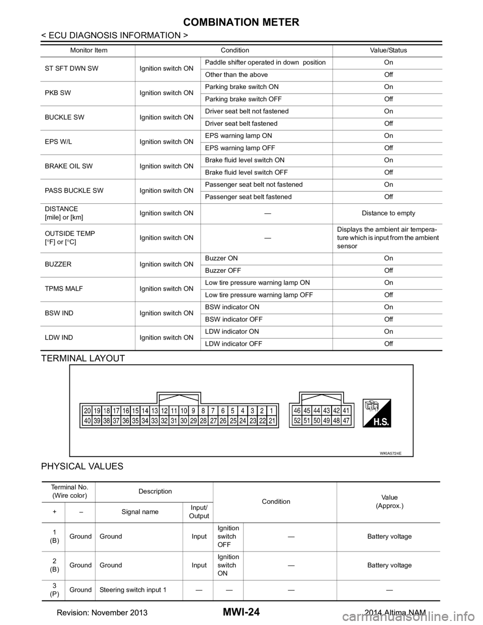
TERMINAL LAYOUT
PHYSICAL VALUES
ST SFT DWN SW Ignition switch ON Paddle shifter operated in down position On
Other than the above Off
PKB SW Ignition switch ON Parking brake switch ON On
Parking brake switch OFF Off
BUCKLE SW Ignition switch ON Driver seat belt not fastened On
Driver seat belt fastened Off
EPS W/L Ignition switch ON EPS warning lamp ON On
EPS warning lamp OFF Off
BRAKE OIL SW Ignition switch ON Brake fluid level switch ON On
Brake fluid level switch OFF Off
PASS BUCKLE SW Ignition switch ON Passenger seat belt not fastened On
Passenger seat belt fastened Off
DISTANCE
[mile] or [km] Ignition switch ON — Distance to empty
OUTSIDE TEMP
[ ° F] or [ °C] Ignition switch ON — Displays the ambient air tempera-
ture which is input from the ambient
sensor
BUZZER Ignition switch ON Buzzer ON On
Buzzer OFF Off
TPMS MALF Ignition switch ON Low tire pressure
warning lamp ON On
Low tire pressure warning lamp OFF Off
BSW IND Ignition switch ON BSW indicator ON On
BSW indicator OFF Off
LDW IND Ignition switch ON LDW indicator ON On
LDW indicator OFF Off
Monitor Item Condition Value/Status
WKIA5724E
Te r m i n a l N o .
(Wire color) Description
ConditionVa l u e
(Approx.)
+ – Signal name Input/
Output
1
(B) Ground Ground Input Ignition
switch
OFF — Battery voltage
2
(B) Ground Ground Input Ignition
switch
ON — Battery voltage
3
(P) Ground Steering switch input 1 — — — —
Revision: November 20132014 Altima NAMRevision: November 20132014 Altima NAM