2014 NISSAN TEANA reset
[x] Cancel search: resetPage 2669 of 4801
![NISSAN TEANA 2014 Service Manual
HAC-20
< SYSTEM DESCRIPTION >[AUTOMATIC AIR CONDITIONER]
SYSTEM
Temperature Control
INFOID:0000000009463100
• When ignition switch is in the ON position, A/C auto amp. always automatically controls NISSAN TEANA 2014 Service Manual
HAC-20
< SYSTEM DESCRIPTION >[AUTOMATIC AIR CONDITIONER]
SYSTEM
Temperature Control
INFOID:0000000009463100
• When ignition switch is in the ON position, A/C auto amp. always automatically controls](/manual-img/5/57390/w960_57390-2668.png)
HAC-20
< SYSTEM DESCRIPTION >[AUTOMATIC AIR CONDITIONER]
SYSTEM
Temperature Control
INFOID:0000000009463100
• When ignition switch is in the ON position, A/C auto amp. always automatically controls temperatur e regardless of front air condi-
tioning operational state.
• A/C auto amp. calculates the target air mix door opening angle depending on set temperature, in-vehicle temperature, ambient
temperature, and sunload.
• Air mix door is controlled depending on the comparison of current
air mix door opening angle and target air mix door opening angle.
• Regardless of in-vehicle temperature, ambient temperature, and
sunload, air mix door is fixed at the fully cold position when set
temperature is 18.0 °C (60 °F), and at the fully hot position when set
temperature is 32.0 °C (90 °F).
Fail-safeINFOID:0000000009463101
FAIL-SAFE FUNCTION
If a communication error exists between the A/C auto amp., and the AV control unit and preset switch for 30
seconds or longer, air conditioning is controlled under the following conditions:
When ambient temperature is less than 3 °C (37 °F) and engine coolant temperature is less than 56 °C (133 °F)
When ambient temperature is 3 °C (37 °F) or more, or engine coolant temperature is 56 °C (133 °F) or more
JMIIA0731GB
Compressor : ON
Air outlet : DEF
Air inlet : FRE (Fresh air intake)
Blower fan speed : AUTO
Set temperature : Setting before communication error occurs
Compressor : ON
Air outlet : AUTO
Air inlet : 20% FRE (20% fresh air intake)
Blower fan speed : AUTO
Set temperature : Setting before communication error occurs
Revision: November 20132014 Altima NAMRevision: November 20132014 Altima NAM
Page 2765 of 4801
![NISSAN TEANA 2014 Service Manual
HAC-116
< SYSTEM DESCRIPTION >[MANUAL AIR CONDITIONER]
COMPONENT PARTS
Mode door motorThe mode door controls the direction the conditioned air passes through the ventilation system.
Through a serie NISSAN TEANA 2014 Service Manual
HAC-116
< SYSTEM DESCRIPTION >[MANUAL AIR CONDITIONER]
COMPONENT PARTS
Mode door motorThe mode door controls the direction the conditioned air passes through the ventilation system.
Through a serie](/manual-img/5/57390/w960_57390-2764.png)
HAC-116
< SYSTEM DESCRIPTION >[MANUAL AIR CONDITIONER]
COMPONENT PARTS
Mode door motorThe mode door controls the direction the conditioned air passes through the ventilation system.
Through a series of levers and gears, the mode door controls the defrost door, the foot door, and the
vent door. There are 5 preset positions: VENT, B/L, FOOT, D/F, and DEF. The FOOT position can be
set to allow some airflow through to the defroster vent, or to completely block the defroster vent using
the CONSULT. The mode door motor receives position commands from the front air control and re-
ports actual door position back via an LCU (Local Control Unit) installed inside the motor. Commands
and responses are sent across the LIN (Local Interconnect Network) to each motor simultaneously,
with each motor having its own unique address, thereby only responding to requests sent to its spe-
cific address. The LCU reads the door position from a Position Balanced Resistor (PBR), also part of
the motor, and returns that information to the front air control. The LCU switches the polarity of the
circuits connected to the DC motor to drive the motor forward or backward as requested by the front
air control.
Refrigerant pressure sensor Refer to
EC-36, "Refrigerant Pressure Sensor"
for QR25DE and EC-562, "Refrigerant Pressure Sen-
sor" for VQ35DE.
Component Description
Revision: November 20132014 Altima NAMRevision: November 20132014 Altima NAM
Page 2835 of 4801
![NISSAN TEANA 2014 Service Manual
INL-14
< SYSTEM DESCRIPTION >
DIAGNOSIS SYSTEM (BCM)
SELF DIAGNOSTIC RESULT
Refer to BCS-52, "DTC Index".
DATA MONITOR
Monitor Item [Unit] Main Description
REQ SW -DR [On/Off] ×Indicates condition o NISSAN TEANA 2014 Service Manual
INL-14
< SYSTEM DESCRIPTION >
DIAGNOSIS SYSTEM (BCM)
SELF DIAGNOSTIC RESULT
Refer to BCS-52, "DTC Index".
DATA MONITOR
Monitor Item [Unit] Main Description
REQ SW -DR [On/Off] ×Indicates condition o](/manual-img/5/57390/w960_57390-2834.png)
INL-14
< SYSTEM DESCRIPTION >
DIAGNOSIS SYSTEM (BCM)
SELF DIAGNOSTIC RESULT
Refer to BCS-52, "DTC Index".
DATA MONITOR
Monitor Item [Unit] Main Description
REQ SW -DR [On/Off] ×Indicates condition of door request switch LH.
REQ SW -AS [On/Off] ×Indicates condition of door request switch RH.
REQ SW -BD/TR [On/Off] ×Indicates condition of trunk opener request switch.
PUSH SW [On/Off] Indicates condition of push-button ignition switch.
SHFTLCK SLNID PER SPLY [On/Off] ×Indicates condition of power supply to shiftlock solenoid.
BRAKE SW 1 [On/Off] ×Indicates condition of brake switch.
BRAKE SW 2 [On/Off] Indicates condition of brake switch.
DETE/CANCL SW [On/Off] ×Indicates condition of P (park) position.
SFT PN/N SW [On/Off] ×Indicates condition of P (park) or N (neutral) position.
UNLK SEN -DR [On/Off] ×Indicates condition of door unlock sensor.
PUSH SW -IPDM [On/Off] Indicates condition of push-button ignition switch received from IPDM E/R
on CAN communication line.
IGN RLY1 -F/B [On/Off] Indicates condition of ignition relay 1 received from IPDM E/R on CAN
communication line.
DETE SW -IPDM [On/Off] Indicates condition of detent switch received from TCM on CAN communi-
cation line.
SFT PN -IPDM [On/Off] Indicates condition of P (park) or N (neutral) position from TCM on CAN
communication line.
SFT P -MET [On/Off] Indicates condition of P (park) position from TCM on CAN communication
line.
SFT N -MET [On/Off] Indicates condition of N (neutral) position from IPDM E/R on CAN commu-
nication line.
ENGINE STATE [STOP/START/CRANK/RUN] ×Indicates condition of engine state from ECM on CAN communication line.
VEH SPEED 1 [mph/km/h] ×Indicates condition of vehicle speed signal received from ABS on CAN
communication line.
VEH SPEED 2 [mph/km/h] ×Indicates condition of vehicle speed signal received from combination
meter on CAN communication line.
DOOR STAT -DR [LOCK/READY/UNLK] ×Indicates condition of driver side door status.
DOOR STAT -AS [LOCK/READY/UNLK] ×Indicates condition of passenger side door status.
DOOR STAT -RR [LOCK/READY/UNLK] ×Indicates condition of rear right side door status.
DOOR STAT -RL [LOCK/READY/UNLK] ×Indicates condition of rear left side door status.
ID OK FLAG [Set/Reset] Indicates condition of Intelligent Key ID.
PRMT ENG STRT [Set/Reset] Indicates condition of engine start possibility.
PRMT RKE STRT [Set/Reset] Indicates condition of engine start possibility from Intelligent Key.
I-KEY OK FLAG [Key ON/Key OFF] ×Indicates condition of Intelligent Key OK flag.
PRBT ENG STRT [Set/Reset] Indicates condition of engine start prohibit.
ID AUTHENT CANCEL TIMER [STOP] Indicates condition of Intelligent Key ID authentication.
ACC BATTERY SAVER [STOP] Indicate s condition of battery saver.
CRNK PRBT TMR [On/Off] Indicates co ndition of crank prohibit timer.
AUT CRNK TMR [On/Off] Indicates co ndition of automatic engine crank timer fr om Intelligent Key.
CRNK PRBT TME [sec] Indicat es condition of engine crank prohibit time.
AUTO CRNK TME [sec] Indicates co ndition of automatic engine crank time from Intelligent Key.
CRANKING TME [sec] Indicates condition of engine cranking time from Intelligent Key.
Revision: November 20132014 Altima NAMRevision: November 20132014 Altima NAM
Page 2982 of 4801
![NISSAN TEANA 2014 Service Manual
LAN
SYSTEMLAN-33
< SYSTEM DESCRIPTION > [CAN]
C
D E
F
G H
I
J
K L
B
A
O P
N
Engine status signal T R R R R
Fuel consumption monitor signal T R R
Fuel filler cap warning display signal T R
Malfunc NISSAN TEANA 2014 Service Manual
LAN
SYSTEMLAN-33
< SYSTEM DESCRIPTION > [CAN]
C
D E
F
G H
I
J
K L
B
A
O P
N
Engine status signal T R R R R
Fuel consumption monitor signal T R R
Fuel filler cap warning display signal T R
Malfunc](/manual-img/5/57390/w960_57390-2981.png)
LAN
SYSTEMLAN-33
< SYSTEM DESCRIPTION > [CAN]
C
D E
F
G H
I
J
K L
B
A
O P
N
Engine status signal T R R R R
Fuel consumption monitor signal T R R
Fuel filler cap warning display signal T R
Malfunctioning indicator lamp signal TR
RT
Oil pressure warning lamp signal T R
Power generation command value
signal TR
Target throttle position signal T R
Wide open throttle position signal T R
EPS operation signal R T
Hydraulic pump electric power steer-
ing warning lamp signal TR
Detention switch signal T R R
Front wiper stop position signal T R
High beam status signal R T
Hood switch signal T R
Interlock/PNP switch signal RT
TR R
Low beam status signal R T
Oil pressure switch signal RT
TR R
Push-button ignition switch status
signal TR
Rear window defogger control signal R T
Sleep ready signal T R
Starter relay status signal T R
Steering lock unit status signal T R
Steering lock relay signal RT
TR
Current gear position signal T R R
CVT position indicator signal T R R
Input shaft revolution signal R T R R
Manual mode indicator signal T R R
N range signal T R
Output shaft revolution signal R T R R
O/D OFF indicator signal
*1TR R
P range signal T R R
Shift position signal T R R
Brake fluid level signal T R
Distance to empty signal T R
Fuel filler cap warning reset signal R T
Fuel level low warning signal T R
Fuel level sensor signal R T Signal name
ECM
EPS
IPDM-E TCM
M&A
STRG AV
AV M
HVAC ABS
BCM
Revision: November 20132014 Altima NAMRevision: November 20132014 Altima NAM
Page 3263 of 4801

MWI-8
< SYSTEM DESCRIPTION >
COMPONENT PARTS
Unit Description
Combination meter Controls the following with the signals received from each unit via CAN communication and the signals
from switches and sensors:
• Speedometer
• Tachometer
• Engine coolant temperature gauge
• Fuel gauge
• Warning lamps
• Indicator lamps
• Meter illumination control
• Meter effect function
• Information display
Meter control switch Transmits the following signals to the combination meter:
• Trip reset switch signal
• Illumination control switch signal (+)
• Illumination control switch signal ( −)
ECM Transmits the following signals to the combination meter via CAN communication:
• Engine speed signal
• Engine coolant temperature signal
• Engine oil pressure warning signal
• Fuel consumption monitor signal
ABS actuator and electric unit
(control unit) Transmits the vehicle speed signal to the combination meter via CAN communication.
Power steering control module Transmits the EPS signal to the combination meter via CAN communication.
BCM Transmits the following signals to the combination meter via CAN communication:
• Tire pressure information
• Position light request signal
• Low tire pressure warning lamp signal
• Door switch signal
• Trunk lamp switch signal
TCM Receives the O/D OFF switch signal from the combination meter via CAN communication.
Transmits the O/D OFF indicator request signal to the combination meter via CAN communication.
CVT shift selector switch
(overdrive co ntrol switch)
(with QR25DE) Transmits the O/D OFF switch signal to the combination meter
Fuel level sensor unit Transmits the fuel level sensor signal to the combination meter.
Seat belt buckle switch LH
(RH similar) Transmits the seat belt buckle switch LH signal to the combination meter.
Air bag diagnosis sensor unit Transmits the following signals to the combination meter:
• Seat belt buckle switch RH signal
• Air bag warning indicator
Engine oil pressure sensor Transmits the engine oil pressure sensor signal to the ECM.
Ambient sensor Transmits the ambient sensor signal to the IPDM E/R.
A/C auto amp. • Receives the ambient sensor signal from the IPDM E/R (with auto A/C).
• Transmits the ambient sensor signal to the combination meter via CAN communication.
Parking brake switch Transmits the parking brake switch signal to the combination meter.
Washer fluid level switch Transmits the washer fluid level switch signal to the combination meter.
Steering switch Transmits the following signals to the information display:
• Display signal
• Menu up signal
• Menu down signal
• Enter signal
• Back signal
IPDM E/R • Receives the ambient sensor signal from the ambient sensor.
• Transmits the ambient sensor signal to the combination meter (without auto A/C).
• Transmits the ambient sensor signal to the A/C auto amp (with auto A/C).
Brake fluid level switch Transmits the brake fluid level switch signal to the combination meter.
Revision: November 20132014 Altima NAMRevision: November 20132014 Altima NAM
Page 3266 of 4801

MWI
SYSTEMMWI-11
< SYSTEM DESCRIPTION >
C
D E
F
G H
I
J
K L
M B
A
O P
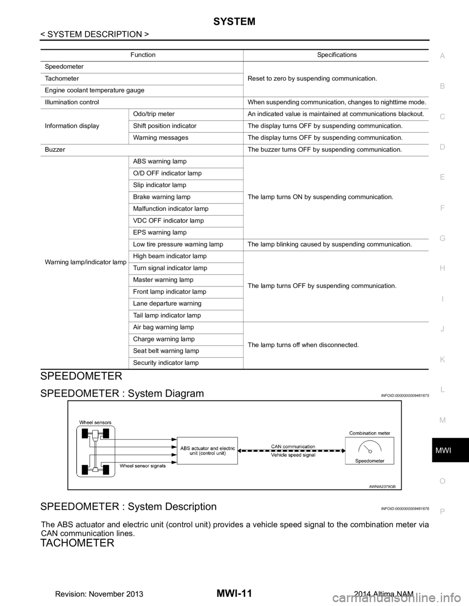
SPEEDOMETER
SPEEDOMETER : System DiagramINFOID:0000000009461675
SPEEDOMETER : System DescriptionINFOID:0000000009461676
The ABS actuator and electric unit (control unit) provi des a vehicle speed signal to the combination meter via
CAN communication lines.
TACHOMETER
Function Specifications
Speedometer Reset to zero by suspending communication.
Tachometer
Engine coolant temperature gauge
Illumination control When suspending communication, changes to nighttime mode.
Information display Odo/trip meter An indicated value is maintained at communications blackout.
Shift position indicator The display turns OFF by suspending communication.
Warning messages The display turns OFF by suspending communication.
Buzzer The buzzer turns OFF by suspending communication.
Warning lamp/indicator lamp ABS warning lamp
The lamp turns ON by suspending communication.
O/D OFF indicator lamp
Slip indicator lamp
Brake warning lamp
Malfunction indicator lamp
VDC OFF indicator lamp
EPS warning lamp
Low tire pressure warning lamp The lamp blinking caused by suspending communication.
High beam indicator lamp
The lamp turns OFF by suspending communication.
Turn signal indicator lamp
Master warning lamp
Front lamp indicator lamp
Lane departure warning
Tail lamp indicator lamp
Air bag warning lamp
The lamp turns off when disconnected.
Charge warning lamp
Seat belt warning lamp
Security indicator lamp
AWNIA2379GB
Revision: November 20132014 Altima NAMRevision: November 20132014 Altima NAM
Page 3273 of 4801

MWI-18
< SYSTEM DESCRIPTION >
DIAGNOSIS SYSTEM (METER)
DIAGNOSIS SYSTEM (METER)
DescriptionINFOID:0000000009461692
COMBINATION METER SELF-DIAGNOSIS MODE
The following meter functions can be checked during Combination Meter Self-Diagnosis Mode:
• Pointer sweep of speedometer, tachometer and gauges.
• Illumination of all LCD segments and color patterns for meter displays.
• Illumination of all lamps/LEDs that are controlled by the combination meter (regardless of switch status).
STARTING COMBINATION METER SELF-DIAGNOSIS MODE
NOTE:
• Check combination meter power supply and ground circuits if self-diagnosis mode does not start. Refer to
MWI-58, "COMBINATION METER : Diagnosis Procedure"
. Replace combination meter if power supply and
ground circuits are found to be normal and self-diagnosis mode does not start. Refer to MWI-82, "Removal
and Installation".
• Combination meter self-diagnosis mode will function with t he ignition switch in ON. Combination meter self-
diagnosis mode will exit upon turning the ignition switch to OFF.
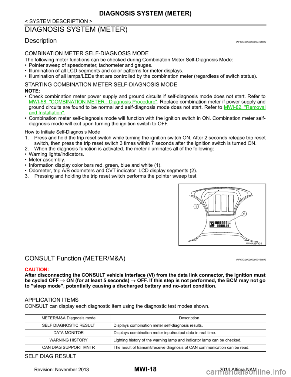
How to Initiate Self-Diagnosis Mode
1. Press and hold the trip reset switch while turning the ignition switch ON. After 2 seconds release trip reset switch, then press the trip reset switch 3 times within 7 seconds after the ignition switch is turned ON.
2. When the diagnosis function is activated, the meter illuminates all of the following:
• Warning lights/indicators.
• Meter assembly.
• Information display color bars red, green, blue and white (1).
• Odometer, trip A/B odometers and CVT indicator LCD display segments (2).
3. Pressing and holding the trip reset switch performs the pointer sweep test.
CONSULT Function (METER/M&A)INFOID:0000000009461693
CAUTION:
After disconnecting the CONSULT vehicle interface (VI) from the data link connector, the ignition must
be cycled OFF → ON (for at least 5 seconds) → OFF. If this step is not performed, the BCM may not go
to ”sleep mode”, potentially causing a di scharged battery and no-start condition.
APPLICATION ITEMS
CONSULT can display each diagnostic item using the diagnostic test modes shown.
SELF DIAG RESULT
AWNIA2543GB
METER/M&A Diagnosis mode Description
SELF DIAGNOSTIC RESULT Displays combin ation meter self-diagnosis results.
DATA MONITOR Displays combination meter input/output data in real time.
WARNING HISTORY Lighting history of the warning lamp and indicator lamp can be checked.
CAN DIAG SUPPORT MNTR The result of transmit/receive diagnosis of CAN communication can be read.
Revision: November 20132014 Altima NAMRevision: November 20132014 Altima NAM
Page 3281 of 4801

MWI-26
< ECU DIAGNOSIS INFORMATION >
COMBINATION METER
31
(W) Ground Ambient sensor ground
(without auto A/C) InputIgnition
switch
ON —0 V
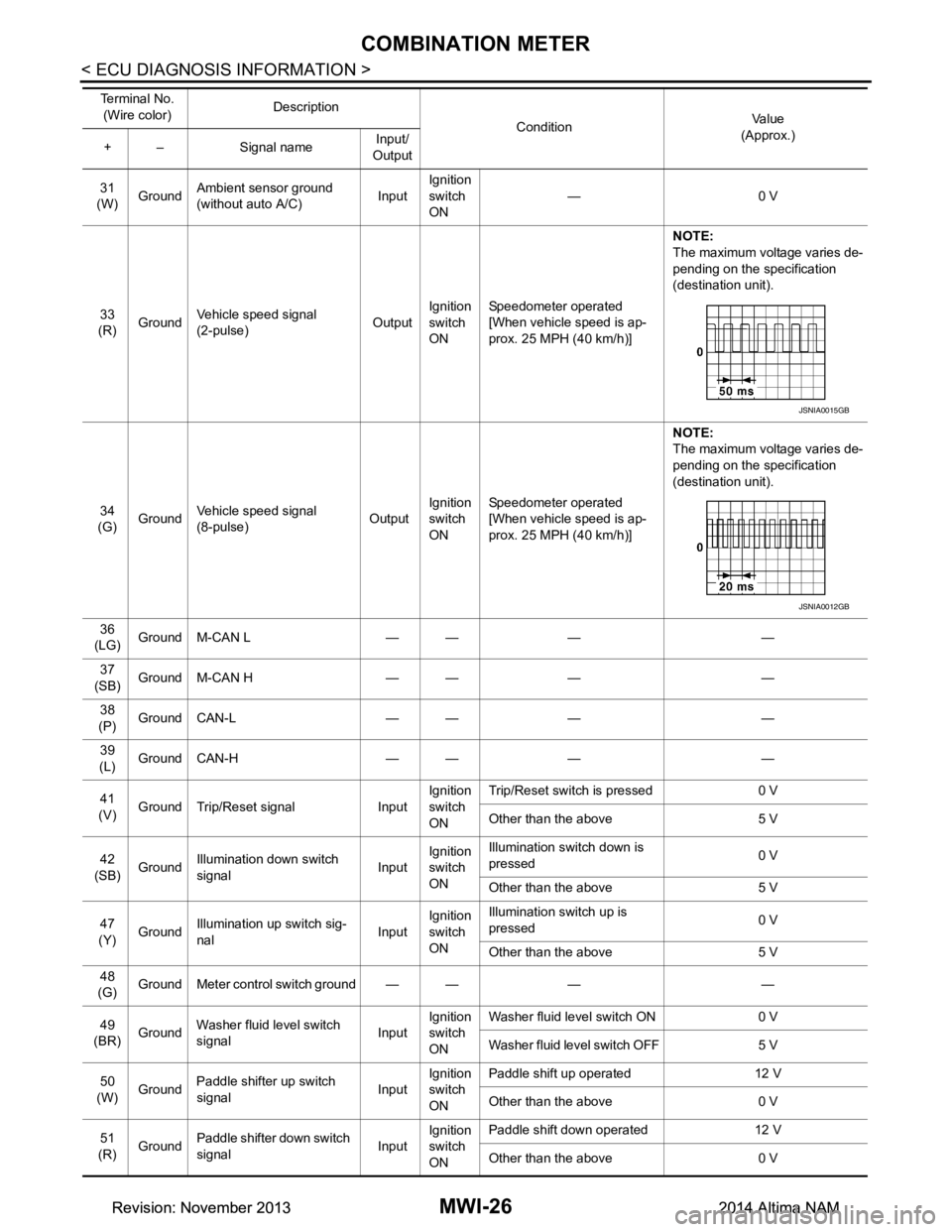
33
(R) Ground Vehicle speed signal
(2-pulse) OutputIgnition
switch
ON Speedometer operated
[When vehicle speed is ap-
prox. 25 MPH (40 km/h)] NOTE:
The maximum voltage varies de-
pending on the specification
(destination unit).
34
(G) Ground Vehicle speed signal
(8-pulse) OutputIgnition
switch
ON Speedometer operated
[When vehicle speed is ap-
prox. 25 MPH (40 km/h)] NOTE:
The maximum voltage varies de-
pending on the specification
(destination unit).
36
(LG) Ground M-CAN L — — — —
37
(SB) Ground M-CAN H — — — —
38
(P) Ground CAN-L — — — —
39
(L) Ground CAN-H — — — —
41
(V) Ground Trip/Reset signal Input Ignition
switch
ON Trip/Reset switch is pressed 0 V
Other than the above 5 V
42
(SB) Ground Illumination down switch
signal InputIgnition
switch
ON Illumination switch down is
pressed 0 V
Other than the above 5 V
47
(Y) Ground
Illumination up switch sig-
nal InputIgnition
switch
ON Illumination switch up is
pressed 0 V
Other than the above 5 V
48
(G) Ground Meter control switch ground — — — —
49
(BR) Ground Washer fluid level switch
signal InputIgnition
switch
ON Washer fluid level switch ON 0 V
Washer fluid level switch OFF 5 V
50
(W) Ground
Paddle shifter up switch
signal InputIgnition
switch
ON Paddle shift up operated 12 V
Other than the above 0 V
51
(R) Ground Paddle shifter down switch
signal InputIgnition
switch
ON Paddle shift down operated 12 V
Other than the above 0 V
Te r m i n a l N o .
(Wire color) Description
ConditionVa l u e
(Approx.)
+ – Signal name Input/
Output
JSNIA0015GB
JSNIA0012GB
Revision: November 20132014 Altima NAMRevision: November 20132014 Altima NAM