2014 NISSAN TEANA reset
[x] Cancel search: resetPage 3779 of 4801
SE-30
< REMOVAL AND INSTALLATION >
FRONT SEAT
PASSENGER SIDE : Removal and Installation - Seat Assembly
INFOID:0000000009462938
REMOVAL
WARNING:
Do not leave any objects (screwdriver s, tools, etc.) on the seat during seat repair. It can lead to per-
sonal injury if the side air bag module should accidentally deploy.
CAUTION:
• When removing or installing the seat trim, handle it carefully to keep dirt out and to avoid damage.
• When checking the power seat circuit for continuity using a circuit tester, do not confuse its connec-
tor with the side air bag module connector. Such an error may cau se the air bag module to deploy.
• Do not drop, tilt, or bump the si de air bag module while installing the seat. Always handle it with
care.
• After front side air bag module inflates, the front seatback assembly must be replaced.
• When removing and installing the seat, use shop cloths to protect components from damage.
• Before removing the front seat, turn the ignition switch OFF, disconnect both battery cables and wait
at least three minutes.
1. Disconnect the negative and positive battery terminal s and wait at least three minutes. Refer to PG-73,
"Removal and Installation (Battery)".
2. Remove the headrest.
3. Slide the seat to the full rearward position.
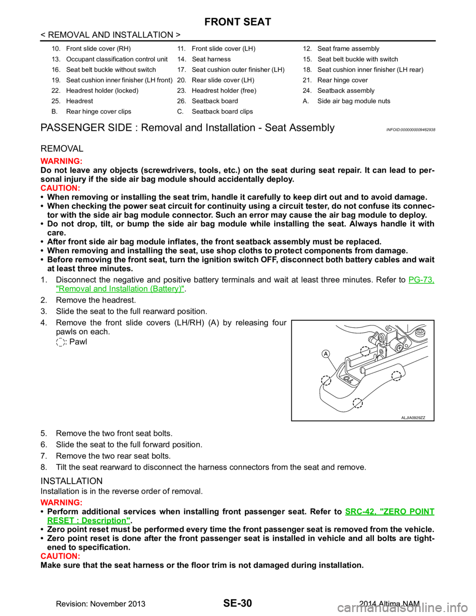
4. Remove the front slide covers (LH/RH) (A) by releasing four pawls on each.
: Pawl
5. Remove the two front seat bolts.
6. Slide the seat to the full forward position.
7. Remove the two rear seat bolts.
8. Tilt the seat rearward to disconnect the harness connectors from the seat and remove.
INSTALLATION
Installation is in the reverse order of removal.
WARNING:
• Perform additional services when instal ling front passenger seat. Refer to SRC-42, "ZERO POINT
RESET : Description".
• Zero point reset must be performed every time th e front passenger seat is removed from the vehicle.
• Zero point reset is done after the front passenger seat is installed in vehicle and all bolts are tight-
ened to specification.
CAUTION:
Make sure that the seat harness or the floor trim is not damaged during installation.
10. Front slide cover (RH) 11. Front sl ide cover (LH) 12. Seat frame assembly
13. Occupant classification control unit 14. Seat harness 15. Seat belt buckle with switch
16. Seat belt buckle without switch 17. Seat cushion outer finisher (LH) 18. Seat cushion inner finisher (LH rear)
19. Seat cushion inner finisher (LH front) 20. Rear slide cover (LH) 21. Rear hinge cover
22. Headrest holder (locked) 23. Headrest holder (free) 24. Seatback assembly
25. Headrest 26. Seatback board A. Side air bag module nuts
B. Rear hinge cover clips C. Seatback board clips
ALJIA0929ZZ
Revision: November 20132014 Altima NAMRevision: November 20132014 Altima NAM
Page 3842 of 4801
SYSTEMSEC-17
< SYSTEM DESCRIPTION >
C
D E
F
G H
I
J
L
M A
B
SEC
N
O P
• The panic alarm does not start when the theft warning alarm is activating and the panic alarm stops when the theft warning alarm is activated.
The priority of the functions are as per the following.
THEFT WARNING ALARM
• The theft warning alarm function activates horns and headlamps intermittently when BCM detects that any
door or hood is opened by unauthorized means whil e the system is in the ARMED state.
• Security indicator lamp on combination meter always blinks when power supply position is any position other
than ON. Security indicator lamp blinking warns that the vehicle is equipped with a vehicle security system.
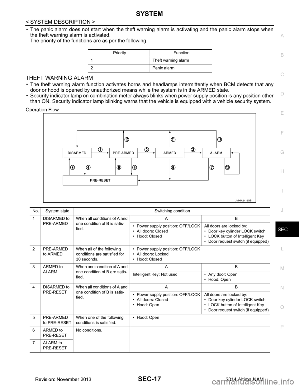
Operation Flow
Priority Function
1 Theft warning alarm
2 Panic alarm
JMKIA5416GB
No. System state Switching condition
1 DISARMED to PRE-ARMED When all conditions of A and
one condition of B is satis-
fied. AB
• Power supply position: OFF/LOCK
• All doors: Closed
• Hood: Closed All doors are locked by:
• Door key cylinder LOCK switch
• LOCK button of Intelligent Key
• Door request switch (if equipped)
2PRE-ARMED to ARMED When all of the following
conditions are satisfied for
30 seconds. • Power supply position: OFF/LOCK
• All doors: Locked
• Hood: Closed
3ARMED to ALARM When one condition of A and
one condition of B are satis-
fied. AB
Intelligent Key: Not used • Any door: Open • Hood: Open
4 DISARMED to PRE-RESET When all conditions of A and
one condition of B is satis-
fied. AB
• Power supply position: OFF/LOCK
• All doors: Closed
• Hood: Open All doors are locked by:
• Door key cylinder LOCK switch
• LOCK button of Intelligent Key
• Door request switch (if equipped)
5PRE-ARMED to PRE-RESET When one of the following
conditions is satisfied. • Hood: Open
6ARMED to PRE-RESET No conditions.
7 ALARM to PRE-RESET
Revision: November 20132014 Altima NAMRevision: November 20132014 Altima NAM
Page 3843 of 4801

SEC-18
< SYSTEM DESCRIPTION >
SYSTEM
NOTE:
• BCM ignores the door key cylinder UNLOCK switch signal input for 1 second after the door key cylinder LOCK switch signal input .
• To lock/unlock all doors by operating remote controller button of Intelligent Key or door request switch (if equipped), Intell igent Key
must be within the detection area of outside key antenna. For details, refer to DLK-21, "System Description"
.
• To open trunk by operating trunk opener switch, Intelligent Key must be within the detection area of outside key antenna. For details,
refer to DLK-41, "System Description"
.
DISARMED Phase
The vehicle security system is not set in the DISAR MED phase. The vehicle security system stays in this
phase while any door is open because it is assumed that the owner is inside or nearby the vehicle. Security
indicator lamp blinks every 2.4 seconds.
When the vehicle security system is reset, eac h phase switches to the DISARMED phase directly.
PRE-ARMED Phase
The PRE-ARMED phase is the transient state bet ween the DISARMED phase and the ARMED phase. This
phase is maintained for 30 seconds so that the owner c an reset the setting due to a mis-operation. This phase
switches to the ARMED phase when vehicle conditions are not changed for 30 seconds. Security indicator
lamp illuminates while being in this phase.
To reset the PRE-ARMED phase, refer to the s witching condition of No. 10 in the table above.
ARMED Phase
The vehicle security system is set and BCM monitors all necessary inputs. If any door or hood is opened with-
out using Intelligent Key, vehicle security system switc hes to the ALARM phase. Security indicator lamp blinks
every 2.4 seconds.
To reset the ARMED phase, refer to the switching condition of No. 11 in the table above.
ALARM Phase
BCM transmits “Theft Warning Horn Request” signal and “High Beam Request” signal intermittently to IPDM
E/R via CAN communication. In this phase, horns and headlamps are activated intermittently for approxi-
mately 50 seconds to warn that the vehicle is a ccessed by unauthorized means. ON/OFF timing of horns and
headlamps are synchronized. After 50 seconds, the vehicle security system returns to the ARMED phase. At
this time, if BCM still detects unauthorized access to t he vehicle, the system is switched to the ALARM phase
again. This RE-ALARM operation is carried out a maximum of 2 times.
To cancel the ALARM operation, refer to the switching condition of No. 12 in the table above.
NOTE:
If a battery terminal is disconnected during the ALARM phase, theft warning alarm stops. But when the battery
terminal is reconnected, theft warning alarm is activated again.
8 PRE-RESET to
DISARMED When one of the following
conditions is satisfied. • Power supply positi
on: ACC/ON/CRANKING/RUN
• Door key cylinder UNLOCK switch: ON
• UNLOCK button of Intelligent Key: ON
• Door request switch (if equipped): ON
• UNLOCK switch of door lock and unlock switch: ON
• Any door: Open
9 PRE-RESET to PRE-ARMED When all of the following
conditions are satisfied. • Power supply position: OFF/LOCK
• All doors: Closed
• Hood: Closed
10 PRE-ARMED to DISARMED When one of the following
conditions is satisfied. • Power supply positi
on: ACC/ON/CRANKING/RUN
• Door key cylinder UNLOCK switch: ON
• UNLOCK button of Intelligent Key: ON
• TRUNK button of Intelligent Key: ON
• Door request switch (if equipped): ON
• Any door: Open
11 A R M E D t o DISARMED When one of the following
conditions is satisfied. • Power supply positi
on: ACC/ON/CRANKING/RUN
• Door key cylinder UNLOCK switch: ON
• UNLOCK button of Intelligent Key: ON
• TRUNK button of In telligent Key: ON
• Door request switch (if equipped): ON
12 ALARM to
DISARMED
13 RE-ALARM When one of the following conditions is satisfied after
the ALARM operation is fin-
ished. • Any door: Open
• Hood: Open
No. System state Switching condition
Revision: November 20132014 Altima NAMRevision: November 20132014 Altima NAM
Page 3844 of 4801

SYSTEMSEC-19
< SYSTEM DESCRIPTION >
C
D E
F
G H
I
J
L
M A
B
SEC
N
O P
PRE-RESET Phase
The PRE-RESET phase is the transient state betw
een each phase and DISARMED phase. If only the condi-
tion of hood is not satisfied, the system switches to the PRE-RESET phase. Then, when any condition is
changed, the system switches to the DISARMED phase or PRE-ARMED phase.
PANIC ALARM
• The panic alarm function activates horns and headlamps intermittently when the owner presses the PANIC
ALARM button of Intelligent Key outside the vehicle while the power supply position is OFF or LOCK.
• When BCM receives panic alarm signal from Intelligent Key, BCM transmits “Theft Warning Horn Request”
signal and “High Beam Request” signal intermittently to IPDM E/R via CAN communication. To prevent the
activation due to mis-operation of Intelligent Key by owner, the panic alarm function is activated when BCM
receives the signal for 0.4 - 0.6 seconds.
• Panic alarm operation is maintained for 25 seconds.
• Panic alarm operation is cancelled when BCM receives one of the following signals:
- LOCK button of Intelligent Key: ON
- UNLOCK button of Intelligent Key: ON
- PANIC ALARM button of Intelligent Key: Long pressed
- Any door request switch (if equipped): ON
Revision: November 20132014 Altima NAMRevision: November 20132014 Altima NAM
Page 3847 of 4801
![NISSAN TEANA 2014 Service Manual
SEC-22
< SYSTEM DESCRIPTION >
DIAGNOSIS SYSTEM (BCM)
ACTIVE TEST
VEH SPEED 2 [mph/km/h]×Indicates condition of vehicle speed signal received from combination
meter on CAN communication line.
DOOR NISSAN TEANA 2014 Service Manual
SEC-22
< SYSTEM DESCRIPTION >
DIAGNOSIS SYSTEM (BCM)
ACTIVE TEST
VEH SPEED 2 [mph/km/h]×Indicates condition of vehicle speed signal received from combination
meter on CAN communication line.
DOOR](/manual-img/5/57390/w960_57390-3846.png)
SEC-22
< SYSTEM DESCRIPTION >
DIAGNOSIS SYSTEM (BCM)
ACTIVE TEST
VEH SPEED 2 [mph/km/h]×Indicates condition of vehicle speed signal received from combination
meter on CAN communication line.
DOOR STAT -DR [LOCK/READY/UNLK] ×Indicates condition of driver side door status.
DOOR STAT -AS [LOCK/READY/UNLK] ×Indicates condition of passenger side door status.
DOOR STAT -RR [LOCK/READY/UNLK] ×Indicates condition of rear right side door status.
DOOR STAT -RL [LOCK/READY/UNLK] ×Indicates condition of rear left side door status.
ID OK FLAG [Set/Reset] Indicates condition of Intelligent Key ID.
PRMT ENG STRT [Set/Reset] Indicates condition of engine start possibility.
PRMT RKE STRT [Set/Reset] Indicates condition of engine start possibility from Intelligent Key.
I-KEY OK FLAG [Key ON/Key OFF] ×Indicates condition of Intelligent Key OK flag.
PRBT ENG STRT [Set/Reset] Indicates condition of engine start prohibit.
ID AUTHENT CANCEL TIMER [STOP] Indicates condition of Intelligent Key ID authentication.
ACC BATTERY SAVER [STOP] Indicate s condition of battery saver.
CRNK PRBT TMR [On/Off] Indicates co ndition of crank prohibit timer.
AUT CRNK TMR [On/Off] Indicates co ndition of automatic engine crank timer fr om Intelligent Key.
CRNK PRBT TME [sec] Indicat es condition of engine crank prohibit time.
AUTO CRNK TME [sec] Indicates co ndition of automatic engine crank time from Intelligent Key.
CRANKING TME [sec] Indicates condition of engine cranking time from Intelligent Key.
DETE SW PWR [On/Off] Indicates condition of detent switch voltage.
ACC RLY -REQ [On/Off] Indicates condition of accessory relay control request.
RKE OPE COUN1 [0-19] ×When remote keyless entry receiver receives the signal transmitted while
operating on Intelligent Key, the numerical value start changing.
RKE OPE COUN2 [0-19] ×When remote keyless entry receiver receives the signal transmitted while
operating on Intelligent Key, the numerical value start changing.
TRNK/HAT MNTR [On/Off] Indicates condition of trunk room lamp switch.
RKE-LOCK [On/Off] Indicates condition of lock signal from Intelligent Key.
RKE-UNLOCK [On/Off] Indicates condition of unlock signal from Intelligent Key.
RKE-TR/BD [On/Off] Indicates condition of trunk open signal from Intelligent Key.
RKE-PANIC [On/Off] Indicates condition of panic signal from Intelligent Key.
RKE-MODE CHG [On/Off] Indicates condition of mode change signal from Intelligent Key. Monitor Item [Unit] Main Description
Test Item Description
INTELLIGENT KEY LINK (CAN) This test is able to check Intelligent Key identification number [Off/ID No1/ID N02/ID No3/ID
No4/ID No5].
INT LAMP This test is able to check interior room lamp operation [On/Off].
FLASHER This test is able to check hazard lamp operation [LH/RH/Off].
HORN This test is able to check horn operation [On].
BATTERY SAVER This test is able to check battery saver operation [On/Off].
TRUNK/BACK DOOR This test is able to check trunk actuator operation [Open].
OUTSIDE BUZZER This test is able to check Intelligent Key warning buzzer operation [On/Off].
INSIDE BUZZER This test is able to check combination meter warning chime operation [Take Out/Knob/Key/
Off].
INDICATOR This test is able to check combination meter warning lamp operation [KEY ON/KEY IND/Off].
IGN CONT2 This test is able to check ignition relay-2 control operation [On/Off].
ENGINE SW ILLUMI This test is able to check push-button ignition switch START indicator operation [On/Off].
Revision: November 20132014 Altima NAMRevision: November 20132014 Altima NAM
Page 3968 of 4801
SR-6
< BASIC INSPECTION >
COLLISION DIAGNOSIS
FOR FRONTAL COLLISION: When SRS is not activated in a collision
CAUTION:
Due to varying models and option levels, not all part s listed in the chart below apply to all vehicles.
WORK PROCEDURE
1. Before performing any of the following steps, ensur e that all vehicle body and structural repairs have been
completed.
2. Check the SRS components using the table below:
Replace any SRS components showing visible signs of damage. (dents, cracks and deformation, etc.)
3. Perform self-diagnosis using CONSULT or air bag warning lamp. Refer to SRC-17, "Trouble Diagnosis
without CONSULT" for details.
Ensure entire SRS operates properly.
4. After the work is completed, perform self-diagnosis to check that no malfunction is detected. Refer to
SRC-15, "SRS Operation Check"
.
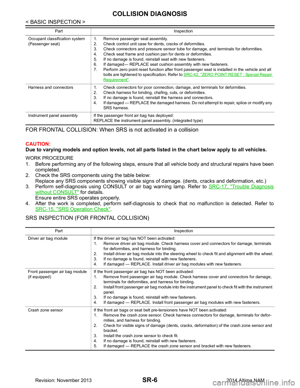
SRS INSPECTION (FOR FRONTAL COLLISION)
Occupant classification system
(Passenger seat) 1. Remove passenger seat assembly.
2. Check control unit case for dents, cracks of deformities.
3. Check connectors and pressure sensor tube for damage, and terminals for deformities.
4. Check seat frame and cushion pan for dents or deformities.
5. If no damage is found, reinstall seat with new fasteners.
6. If damaged— REPLACE seat cushion assembly with new fasteners.
7. Perform zero point reset function after front passenger seat is installed in the vehicle and all bolts are tightened to specification. Refer to SRC-42, "ZERO POINT RESET : Special Repair
Requirement".
Harness and connectors 1. Check connectors for poor connection, damage, and terminals for deformities. 2. Check harness for binding, chafing, cuts, or deformities.
3. If no damage is found, reinstall the harness and connectors.
4. If damaged — REPLACE the damaged harness. Do not attempt to repair, splice or modify any SRS harness.
Instrument panel assembly If the passenger front air bag has deployed: REPLACE the instrument panel assembly. (integrated type)
Part Inspection
Part Inspection
Driver air bag module If the driver air bag has NOT been activated: 1. Remove driver air bag module. Check harness cover and connectors for damage, terminals for deformities, and harness for binding.
2. Install driver air bag module into the steering wheel to check fit and alignment with the wheel.
3. If no damage is found, reinstall with new fasteners.
4. If damaged — REPLACE. Install driver air bag modules with new fasteners.
Front passenger air bag module
(if equipped) If the front passenger air bag has NOT been activated:
1. Remove front passenger air bag module. Check harness cover and connectors for damage, terminals for deformities, and harness for binding.
2. Install front passenger air bag module into the instrument panel to check fit with the instrument panel.
3. If no damage is found, reinstall with new fasteners.
4. If damaged — REPLACE. Install front passenger air bag modules with new fasteners.
Crash zone sensor If the front air bags or seat belt pre-tensioners have NOT been activated: 1. Remove the crash zone sensor. Check harness connectors for damage, terminals for defor-mities, and harness for binding.
2. Check for visible signs of damage (dents, cracks, deformation) of the crash zone sensor and bracket.
3. Install the crash zone sensor to check fit.
4. If no damage is found, reinstall with new fasteners.
5. If damaged — REPLACE the crash zone sensor and bracket with new fasteners.
Revision: November 20132014 Altima NAM
Page 3969 of 4801
COLLISION DIAGNOSISSR-7
< BASIC INSPECTION >
C
D E
F
G
I
J
K L
M A
B
SR
N
O P
For Side and Rollover CollisionINFOID:0000000009463068
FOR SIDE AND ROLLOVER COLLISION: When SRS is activated in a collision
CAUTION:
Due to varying models and option levels, not all parts listed in the chart below apply to all vehicles.
WORK PROCEDURE
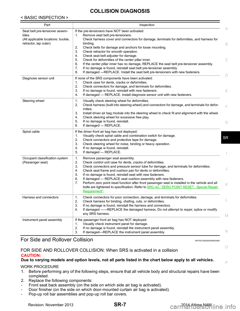
1. Before performing any of the following steps, ensur e that all vehicle body and structural repairs have been
completed.
2. Replace the following components:
- Front seat back assembly (on the side on which side air bag is activated).
- Door finisher (on the side on which door-mounted curtain air bag is activated).
- Pop-up roll bar assemblies and pop-up roll bar covers.
Seat belt pre-tensioner assem-
blies
(All applicable locations: buckle,
retractor, lap outer) If the pre-tensioners have NOT been activated:
1. Remove seat belt pre-tensioners.
Check harness cover and connectors for damage, terminals for deformities, and harness for
binding.
2. Check belts for damage and anchors for loose mounting.
3. Check retractor for smooth operation.
4. Check seat belt adjuster for damage.
5. Check for deformities of the center pillar inner.
6. If the center pillar inner has no damage, REPLACE the seat belt pre-tensioner assembly.
7. If no damage is found, reinstall seat belt pre-tensioner assembly.
8. If damaged —REPLACE. Install the seat belt pre-tensioners with new fasteners.
Diagnosis sensor unit If none of the SRS components have been activated: 1. Check case for dents, cracks or deformities.
2. Check connectors for damage, and terminals for deformities.
3. If no damage is found, reinstall with new fasteners.
4. If damaged — REPLACE. Install diagnosis sensor unit with new fasteners.
Steering wheel 1. Visually check steering wheel for deformities. 2. Check harness (built into steering wheel) and connectors for damage, and terminals for defor-mities.
3. Install driver air bag module into the steering wheel to check fit and alignment with the wheel.
4. Check steering wheel for excessive free play.
5. If no damage is found, reinstall.
6. If damaged — REPLACE.
Spiral cable If the driver front air bag has not deployed: 1. Visually check spiral cable and combination switch for damage.
2. Check connectors and protective tape for damage.
3. Check steering wheel for noise, binding or heavy operation.
4. If no damage is found, reinstall.
5. If damaged — REPLACE.
Occupant classification system
(Passenger seat) 1. Remove passenger seat assembly.
2. Check control unit case for dents, cracks of deformities.
3. Check connectors and pressure sensor tube for damage, and terminals for deformities.
4. Check seat frame and cushion pan for dents or deformities.
5. If no damage is found, reinstall seat with new fasteners.
6. If damaged — REPLACE seat cushion assembly with new fasteners.
7. Perform zero point reset function after front passenger seat is installed in the vehicle and all
bolts are tightened to specification. Refer to SRC-42, "ZERO POINT RESET : Special Repair
Requirement".
Harness and connectors 1. Check connectors for poor connection, damage, and terminals for deformities. 2. Check harness for binding, chafing, cuts, or deformities.
3. If no damage is found, reinstall the harness and connectors.
4. If damaged ——REPLACE the damaged harness. Do not attempt to repair, splice or modify any SRS harness.
Instrument panel assembly If the passenger front air bag has NOT deployed: 1. Visually check instrument panel for damage.
2. If no damage is found, reinstall the instrument panel assembly.
3. If damaged—REPLACE the instrument panel assembly.
Part Inspection
Revision: November 20132014 Altima NAM
Page 3976 of 4801
SR-14
< REMOVAL AND INSTALLATION >
DRIVER AIR BAG MODULE
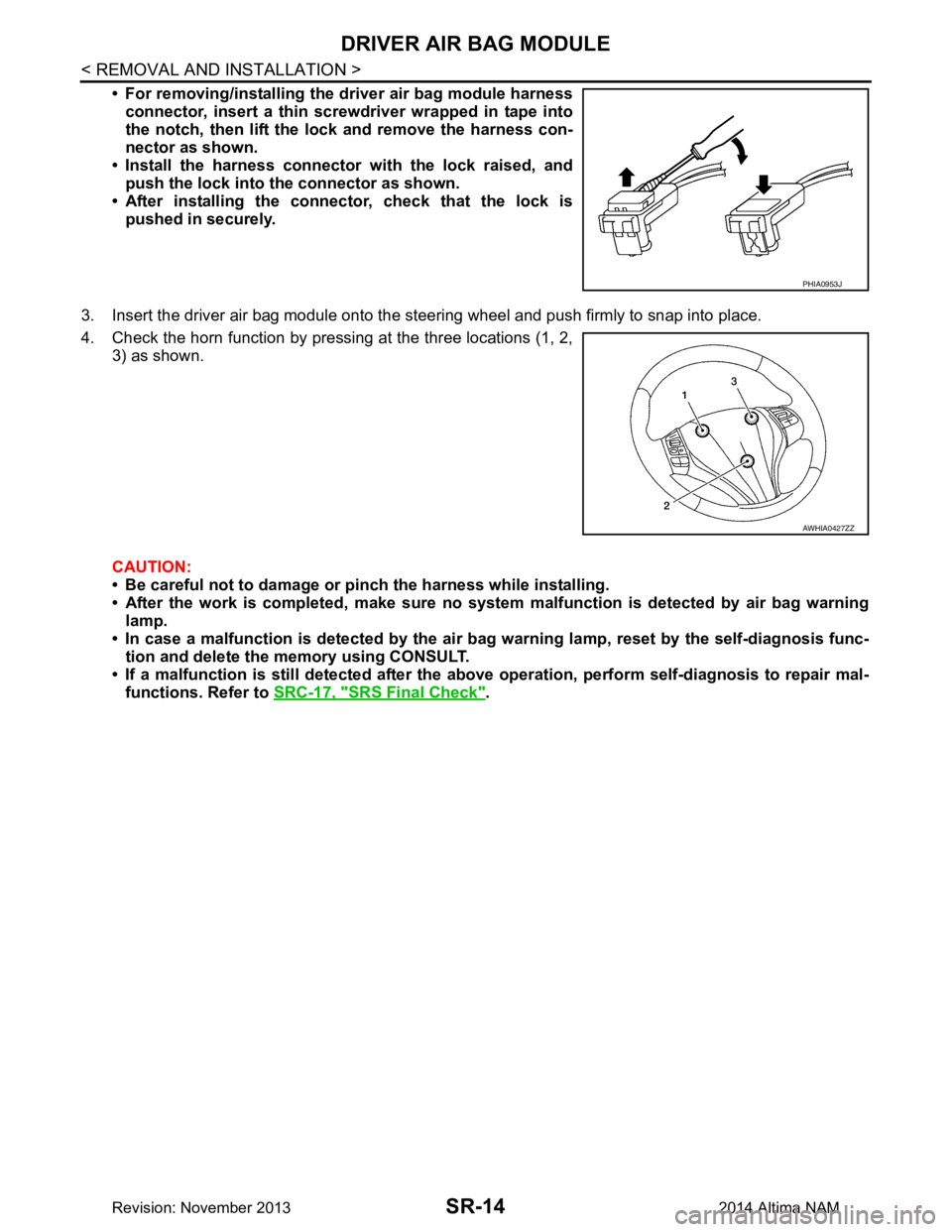
• For removing/installing the driver air bag module harnessconnector, insert a thin screwdriver wrapped in tape into
the notch, then lift the lock and remove the harness con-
nector as shown.
• Install the harness connector with the lock raised, and push the lock into the connector as shown.
• After installing the conn ector, check that the lock is
pushed in securely.
3. Insert the driver air bag module onto the st eering wheel and push firmly to snap into place.
4. Check the horn function by pressing at the three locations (1, 2, 3) as shown.
CAUTION:
• Be careful not to damage or pinch the harness while installing.
• After the work is completed, make sure no syst em malfunction is detected by air bag warning
lamp.
• In case a malfunction is detected by the air bag warning lamp, reset by the self-diagnosis func-
tion and delete the memory using CONSULT.
• If a malfunction is still detected after the abo ve operation, perform self-diagnosis to repair mal-
functions. Refer to SRC-17, "SRS Final Check"
.
PHIA0953J
AWHIA0427ZZ
Revision: November 20132014 Altima NAM