2014 NISSAN TEANA CVT
[x] Cancel search: CVTPage 2221 of 4801
![NISSAN TEANA 2014 Service Manual
ENGINE ASSEMBLYEM-223
< UNIT REMOVAL AND INSTALLATION > [VQ35DE]
C
D E
F
G H
I
J
K L
M A
EM
NP
O
• Start engine. With engine speed increased, check again for fuel leakage at connection points.
� NISSAN TEANA 2014 Service Manual
ENGINE ASSEMBLYEM-223
< UNIT REMOVAL AND INSTALLATION > [VQ35DE]
C
D E
F
G H
I
J
K L
M A
EM
NP
O
• Start engine. With engine speed increased, check again for fuel leakage at connection points.
�](/manual-img/5/57390/w960_57390-2220.png)
ENGINE ASSEMBLYEM-223
< UNIT REMOVAL AND INSTALLATION > [VQ35DE]
C
D E
F
G H
I
J
K L
M A
EM
NP
O
• Start engine. With engine speed increased, check again for fuel leakage at connection points.
• Run engine to check for unusual noise and vibration. NOTE:
If hydraulic pressure inside timing chain tensioner dr ops after removal and installation, slack in the guide
may generate a pounding noise during and just after engine start. However, this is normal. Noise will stop
after hydraulic pressure rises.
• Warm up engine thoroughly to make sure there is no leak age of fuel, exhaust gas, or any oils/fluids including
engine oil and engine coolant.
• Bleed air from passages in lines and hoses, such as in cooling system.
• After cooling down engine, again check oil/fluid levels including engine oil and engine coolant. Refill to spec- ified level, if necessary.
• Summary of the inspection items:
*Power steering fluid, brake fluid, etc. Item Before starting engine Engine running After engine stopped
Engine coolant Level Leakage Level
Engine oil Level Leakage Level
Transmission/
transaxle fluid CVT Models Leakage Level/Leakage Leakage
Other oils and fluids* Level Leakage Level
Fuel Leakage Leakage Leakage
Exhaust gas — Leakage —
Revision: November 20132014 Altima NAM
Page 2290 of 4801
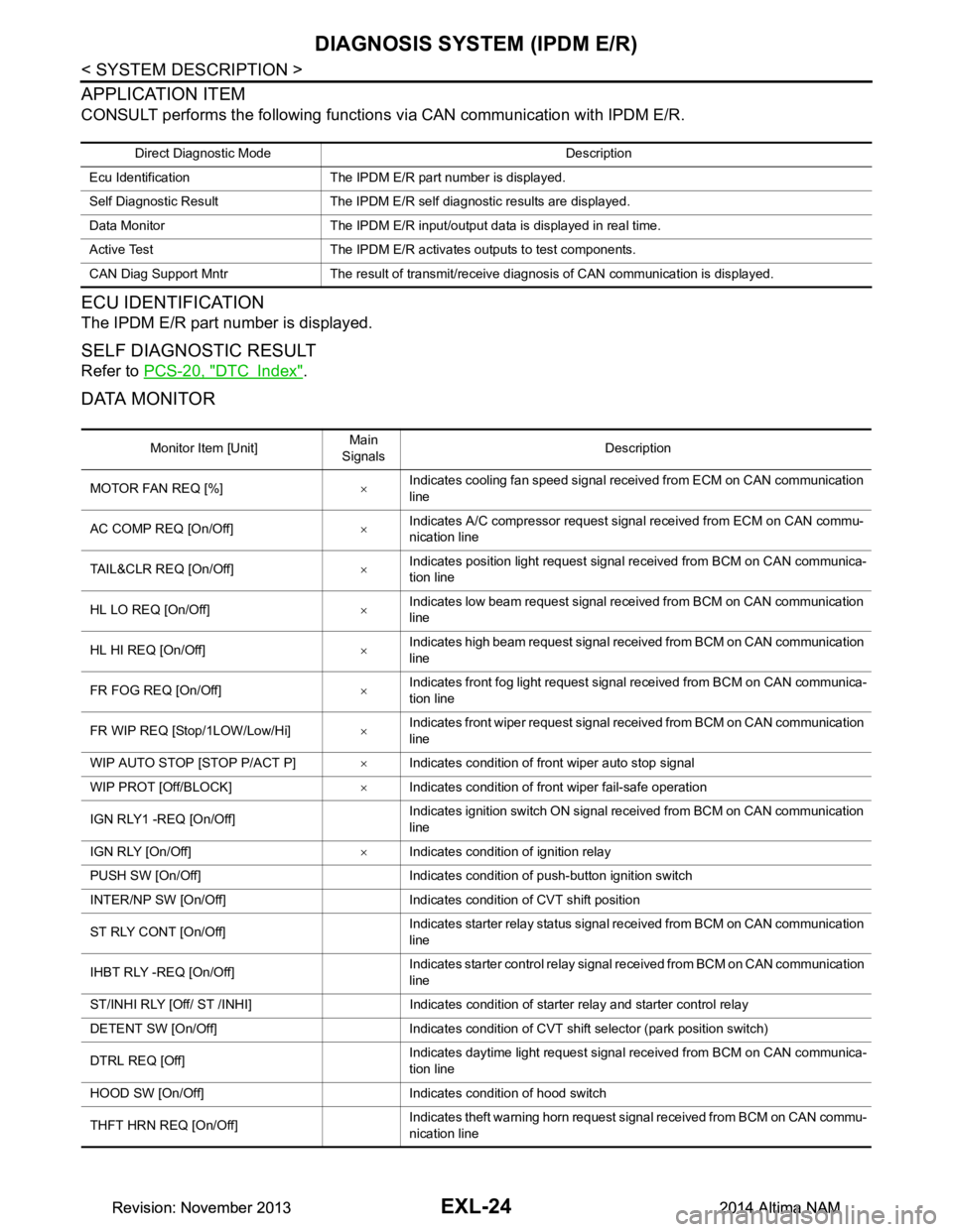
EXL-24
< SYSTEM DESCRIPTION >
DIAGNOSIS SYSTEM (IPDM E/R)
APPLICATION ITEM
CONSULT performs the following functions via CAN communication with IPDM E/R.
ECU IDENTIFICATION
The IPDM E/R part number is displayed.
SELF DIAGNOSTIC RESULT
Refer to PCS-20, "DTC Index".
DATA MONITOR
Direct Diagnostic Mode Description
Ecu Identification The IPDM E/R part number is displayed.
Self Diagnostic Result The IPDM E/R self diagnostic results are displayed.
Data Monitor The IPDM E/R input/output data is displayed in real time.
Active Test The IPDM E/R activates outputs to test components.
CAN Diag Support Mntr The result of transmit/receive diagnosis of CAN communication is displayed.
Monitor Item [Unit] Main
Signals Description
MOTOR FAN REQ [%] ×Indicates cooling fan speed signal received from ECM on CAN communication
line
AC COMP REQ [On/Off] ×Indicates A/C compressor request signal received from ECM on CAN commu-
nication line
TAIL&CLR REQ [On/Off] ×Indicates position light request signal received from BCM on CAN communica-
tion line
HL LO REQ [On/Off] ×Indicates low beam request signal received from BCM on CAN communication
line
HL HI REQ [On/Off] ×Indicates high beam request signal received from BCM on CAN communication
line
FR FOG REQ [On/Off] ×Indicates front fog light request signal received from BCM on CAN communica-
tion line
FR WIP REQ [Stop/1LOW/Low/Hi] ×Indicates front wiper request signal received from BCM on CAN communication
line
WIP AUTO STOP [STOP P/ACT P] ×Indicates condition of front wiper auto stop signal
WIP PROT [Off/BLOCK] ×Indicates condition of front wiper fail-safe operation
IGN RLY1 -REQ [On/Off] Indicates ignition switch ON signal received from BCM on CAN communication
line
IGN RLY [On/Off] ×Indicates condition of ignition relay
PUSH SW [On/Off] Indicates condition of push-button ignition switch
INTER/NP SW [On/Off] Indicates condition of CVT shift position
ST RLY CONT [On/Off] Indicates starter relay status signal received from BCM on CAN communication
line
IHBT RLY -REQ [On/Off] Indicates starter control relay signal received from BCM on CAN communication
line
ST/INHI RLY [Off/ ST /INHI] Indicates condition of starter relay and starter control relay
DETENT SW [On/Off] Indicates condition of CVT shift selector (park position switch)
DTRL REQ [Off] Indicates daytime light request signal received from BCM on CAN communica-
tion line
HOOD SW [On/Off] Indicates condition of hood switch
THFT HRN REQ [On/Off] Indicates theft warning horn request signal received from BCM on CAN commu-
nication line
Revision: November 20132014 Altima NAMRevision: November 20132014 Altima NAM
Page 2425 of 4801
SQUEAK AND RATTLE TROUBLE DIAGNOSESEXT-11
< PERIODIC MAINTENANCE >
C
D E
F
G H
I
J
L
M A
B
EXT
N
O P
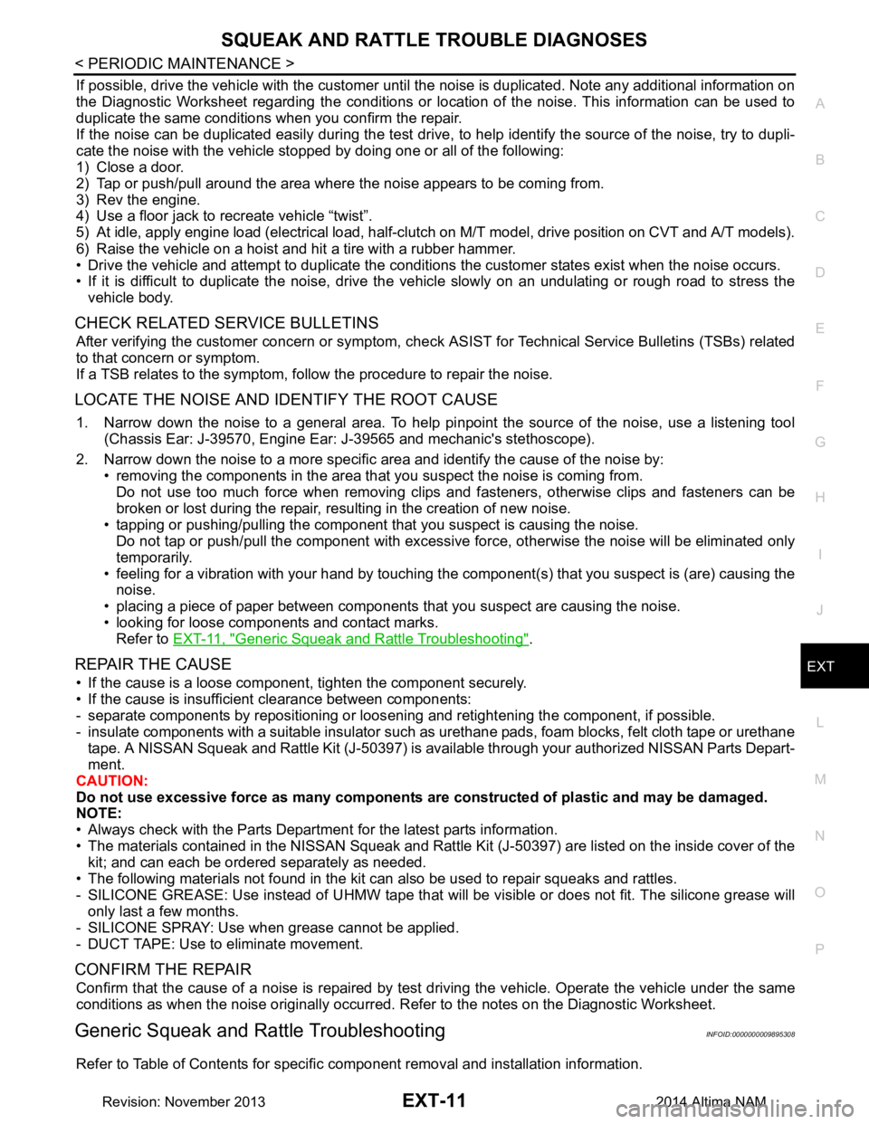
If possible, drive the vehicle with the customer until the noise is duplicated. Note any additional information on
the Diagnostic Worksheet regarding the conditions or lo cation of the noise. This information can be used to
duplicate the same conditions when you confirm the repair.
If the noise can be duplicated easily during the test drive, to help identify the source of the noise, try to dupli-
cate the noise with the vehicle stopped by doing one or all of the following:
1) Close a door.
2) Tap or push/pull around the area where the noise appears to be coming from.
3) Rev the engine.
4) Use a floor jack to recreate vehicle “twist”.
5) At idle, apply engine load (electrical load, half-clutch on M/T model, drive position on CVT and A/T models).
6) Raise the vehicle on a hoist and hit a tire with a rubber hammer.
• Drive the vehicle and attempt to duplicate the conditions the customer states exist when the noise occurs.
• If it is difficult to duplicate the noise, drive the vehicle slowly on an undulating or rough road to stress the
vehicle body.
CHECK RELATED SERVICE BULLETINS
After verifying the customer concern or symptom, che ck ASIST for Technical Service Bulletins (TSBs) related
to that concern or symptom.
If a TSB relates to the symptom, follow the procedure to repair the noise.
LOCATE THE NOISE AND IDENTIFY THE ROOT CAUSE
1. Narrow down the noise to a general area. To help pi npoint the source of the noise, use a listening tool
(Chassis Ear: J-39570, Engine Ear: J-39565 and mechanic's stethoscope).
2. Narrow down the noise to a more specific area and identify the cause of the noise by: • removing the components in the area that you suspect the noise is coming from.Do not use too much force when removing clips and fasteners, otherwise clips and fasteners can be
broken or lost during the repair, resulting in the creation of new noise.
• tapping or pushing/pulling the component that you suspect is causing the noise.
Do not tap or push/pull the component with excessive force, otherwise the noise will be eliminated only
temporarily.
• feeling for a vibration with your hand by touching the component(s) that you suspect is (are) causing the
noise.
• placing a piece of paper between components that you suspect are causing the noise.
• looking for loose components and contact marks. Refer to EXT-11, "Generic Squeak and Rattle Troubleshooting"
.
REPAIR THE CAUSE
• If the cause is a loose component, tighten the component securely.
• If the cause is insufficient clearance between components:
- separate components by repositioning or loos ening and retightening the component, if possible.
- insulate components with a suitable insulator such as urethane pads, foam blocks, felt cloth tape or urethane
tape. A NISSAN Squeak and Rattle Kit (J-50397) is av ailable through your authorized NISSAN Parts Depart-
ment.
CAUTION:
Do not use excessive force as many components are constructed of plastic and may be damaged.
NOTE:
• Always check with the Parts Department for the latest parts information.
• The materials contained in the NISSAN Squeak and Rattle Kit (J-50397) are listed on the inside cover of the
kit; and can each be ordered separately as needed.
• The following materials not found in the kit can also be used to repair squeaks and rattles.
- SILICONE GREASE: Use instead of UHMW tape that will be visible or does not fit. The silicone grease will
only last a few months.
- SILICONE SPRAY: Use when grease cannot be applied.
- DUCT TAPE: Use to eliminate movement.
CONFIRM THE REPAIR
Confirm that the cause of a noise is repaired by test driving the vehicle. Operate the vehicle under the same
conditions as when the noise originally occurred. Refer to the notes on the Diagnostic Worksheet.
Generic Squeak and Rattle TroubleshootingINFOID:0000000009895308
Refer to Table of Contents for specific component removal and installation information.
Revision: November 20132014 Altima NAM
Page 2464 of 4801
FAX-12
< REMOVAL AND INSTALLATION >
FRONT DRIVE SHAFT
1. Check CVT fluid level and leakage. Refer to TM-84, "Adjustment" (REOF10D), TM-286, "Adjustment"
(REOF10E).
2. Check wheel alignment. Refer to FSU-7, "Inspection and Adjustment"
.
3. Adjust the neutral position of the steering angle sensor. Refer to BRC-58, "Work Procedure"
.
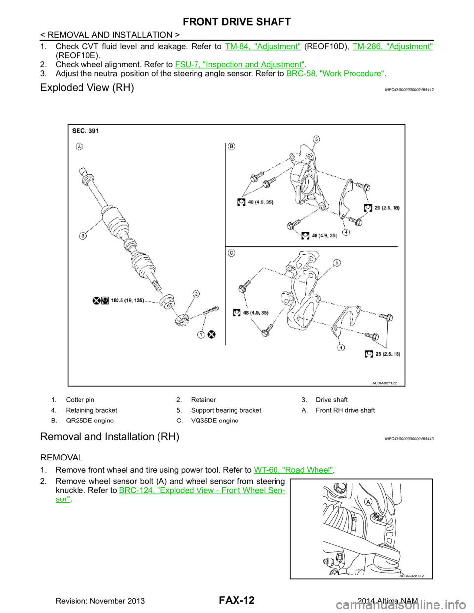
Exploded View (RH)INFOID:0000000009464442
Removal and Installation (RH)INFOID:0000000009464443
REMOVAL
1. Remove front wheel and tire using power tool. Refer to WT-60, "Road Wheel".
2. Remove wheel sensor bolt (A) and wheel sensor from steering knuckle. Refer to BRC-124, "Exploded View - Front Wheel Sen-
sor".
1. Cotter pin 2. Retainer 3. Drive shaft
4. Retaining bracket 5. Support bearing bracket A. Front RH drive shaft
B. QR25DE engine C. VQ35DE engine
ALDIA0371ZZ
ALDIA0287ZZ
Revision: November 20132014 Altima NAM
Page 2466 of 4801
FAX-14
< REMOVAL AND INSTALLATION >
FRONT DRIVE SHAFT
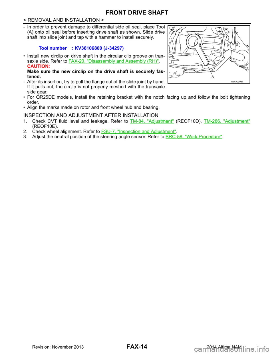
- In order to prevent damage to differential side oil seal, place Tool(A) onto oil seal before inserting drive shaft as shown. Slide drive
shaft into slide joint and tap with a hammer to install securely.
• Install new circlip on drive shaft in the circular clip groove on tran- saxle side. Refer to FAX-20, "Disassembly and Assembly (RH)"
.
CAUTION:
Make sure the new circlip on the drive shaft is securely fas-
tened.
- After its insertion, try to pull the flange out of the slide joint by hand. If it pulls out, the circlip is not properly meshed with the transaxle
side gear.
• For QR25DE models, install the retaining bracket with the notch facing up and follow the bolt tightening
order.
• Align the marks made on rotor and front wheel hub and bearing.
INSPECTION AND ADJUSTMENT AFTER INSTALLATION
1. Check CVT fluid level and leakage. Refer to TM-84, "Adjustment" (REOF10D), TM-286, "Adjustment"
(REOF10E).
2. Check wheel alignment. Refer to FSU-7, "Inspection and Adjustment"
.
3. Adjust the neutral position of the steering angle sensor. Refer to BRC-58, "Work Procedure"
.
Tool number : KV38106800 (J-34297)
WDIA0298E
Revision: November 20132014 Altima NAM
Page 2529 of 4801

GI-1
GENERAL INFORMATION
C
D E
F
G H
I
J
K L
M B
GI
SECTION GI
N
O P
CONTENTS
GENERAL INFORMATION
HOW TO USE THIS MANU AL ......................3
HOW TO USE THIS MANUAL ....................... .....3
Description .......................................................... ......3
Terms ........................................................................3
Units ..........................................................................3
Contents ....................................................................3
Relation between Illustrations and Descriptions .......4
Components ..............................................................4
HOW TO FOLLOW TROUBLE DIAGNOSES .....6
Description ................................................................6
How to Follow Test Groups in Trouble Diagnosis ......6
Key to Symbols Signifying Measurements or Pro-
cedures ............................................................... ......
7
HOW TO READ WIRING DIAGRAMS ................9
Connector symbols ............................................. ......9
Sample/wiring diagram -example- ...........................10
Description ..............................................................11
ABBREVIATIONS .......................................... ....13
Abbreviation List .................................................. ....13
TIGHTENING TORQUE OF STANDARD
BOLTS ............................................................ ....
18
Description .......................................................... ....18
Tightening Torque Table (New Standard Includ-
ed) ....................................................................... ....
18
RECOMMENDED CHEMICAL PRODUCTS
AND SEALANTS ............................................ ....
21
Recommended Chemical Products and Sealants ....21
VEHICLE INFORMATION ............................22
IDENTIFICATION INFORMATION ................. ....22
Model Variation ................................................... ....22
Identification Number ..............................................23
Identification Plate ...................................................24
Engine Serial Number .............................................24
CVT Number ...........................................................25
Dimensions .......................................................... ....25
Wheels & Tires ........................................................25
PRECAUTION ..............................................26
PRECAUTIONS .................................................26
Description ........................................................... ....26
Precaution for Supplemental Restraint System
(SRS) "AIR BAG" and "SEAT BELT PRE-TEN-
SIONER" ............................................................. ....
26
Precautions For Xenon Headlamp Service .............26
Procedures without Cowl Top Cover .......................27
Cautions in Removing Battery Terminal and AV
Control Unit .......................................................... ....
27
General Precautions ................................................27
Three Way Catalyst .................................................29
Fuel (Regular Unleaded Gasoline Recommend-
ed) QR25DE ........................................................ ....
29
Fuel (Regular Unleaded Gasoline Recommend-
ed) VQ35DE ........................................................ ....
29
Multiport Fuel Injection System or Engine Control
System ................................................................. ....
29
Hoses ......................................................................29
Engine Oils ..............................................................30
Air Conditioning .......................................................31
LIFTING POINT .................................................32
Special Service Tool ................................................32
Pantograph Jack ......................................................32
Garage Jack and Safety Stand ................................33
2-Pole Lift ................................................................34
Board-on Lift ............................................................35
TOW TRUCK TOWING .....................................36
Tow Truck Towing ...................................................36
Vehicle Recovery (Freeing a Stuck Vehicle) ...........36
WIRING DIAGRAM ......................................38
CONSULT CHECKING SYSTEM .....................38
Wiring Diagram .................................................... ....38
Revision: November 20132014 Altima NAMRevision: November 20132014 Altima NAM
Page 2541 of 4801

ABBREVIATIONSGI-13
< HOW TO USE THIS MANUAL >
C
D E
F
G H
I
J
K L
M B
GI
N
O PABBREVIATIONS
Abbreviation ListINFOID:0000000009462979
The following ABBREVIATIONS are used:
A
B
C
D
ABBREVIATION DESCRIPTION A/C Air conditioner
A/C Air conditioning
A/F sensor Air fuel ratio sensor A/T Automatic transaxle/transmission
ABS Anti-lock braking system
ACCS Advance climate control system ACL Air cleaner
AP Accelerator pedal
APP Accelerator pedal position AV Audio visual
AVM Around view monitor
AWD All wheel drive
ABBREVIATION DESCRIPTION BARO Barometric pressureBCI Backup collision intervention
BCM Body control module
BLSD Brake limited slip differential BPP Brake pedal positionBSI Blind spot intervention
BSW Blind spot warning
ABBREVIATION DESCRIPTION CKP Crankshaft positionCL Closed loop
CMP Camshaft position CPP Clutch pedal positionCTP Closed throttle position
CVT Continuously variable transaxle/transmission
ABBREVIATION DESCRIPTION D
1Drive range first gear
D
2Drive range second gear
D
3Drive range third gear
D
4Drive range fourth gear
DCA Distance control assist
DDS Downhill drive support DFI Direct fuel injection system
DLC Data link connector
DTC Diagnostic trouble code
Revision: November 20132014 Altima NAMRevision: November 20132014 Altima NAM
Page 2550 of 4801
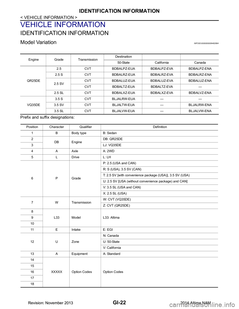
GI-22
< VEHICLE INFORMATION >
IDENTIFICATION INFORMATION
VEHICLE INFORMATION
IDENTIFICATION INFORMATION
Model VariationINFOID:0000000009462984
Prefix and suffix designations:
Engine Grade TransmissionDestination
50-State California Canada
QR25DE 2.5 CVT BDBALPZ-EUA BDBALPZ-EVA BDBALPZ-ENA
2.5 S CVT BDBALRZ-EUA BDBALRZ-EVA BDBALRZ-ENA
2.5 SV CVT BDBALUZ-EUA BDBALUZ-EVA BDBALUZ-ENA
CVT BDBALTZ-EUA BDBALTZ-EVA —
2.5 SL CVT BDBALXZ-EUA BDBALXZ-EVA BDBALVZ-ENA
VQ35DE 3.5 S CVT BLJALRW-EUA — —
3.5 SV CVT BLJALTW-EUA — BLJALRW-ENA 3.5 SL CVT BLJALVW-EUA — BLJALVW-ENA
Position Character Qualifier Definition 1 B Body type B: Sedan
2 DB Engine DB: QR25DE
3LJ: VQ35DE
4AAxle A: 2WD
5LDrive L: LH
6PGrade P: 2.5 (USA and CAN)
R: S (USA), 3.5 SV (CAN)
T: 2.5 SV [with convenience package (USA)], 3.5 SV (USA)
U: 2.5 SV [USA (without convenience package) and CAN]
V: 3.5 SL (USA and CAN)
X: 2.5 SL (USA)
7 W Transmission W: CVT (VQ35DE)
Z: CVT (QR25DE)
8 L33 Model L33: Altima
9
10 11 E I n t a k e E : E G I
12 U Zone N: Canada
U: 50-State
V: California
13 A Equipment A: Standard
14
XXXXX Option Codes Option Codes
15
16
17
18
Revision: November 20132014 Altima NAMRevision: November 20132014 Altima NAM