2014 NISSAN TEANA wheel bolts
[x] Cancel search: wheel boltsPage 2514 of 4801
TRANSVERSE LINKFSU-13
< REMOVAL AND INSTALLATION >
C
D
F
G H
I
J
K L
M A
B
FSU
N
O P
- If axial end play exceeds the standard value, replace transverse link.
INSTALLATION
Installation is in the reverse order of removal.
• Perform final tightening of bolts and nuts at the front suspension member, under unladen conditions with
tires on level ground.
• Check wheel alignment. Refer to FSU-7, "Inspection and Adjustment"
.
• Adjust neutral position of steering angle sensor. Refer to BRC-58, "Work Procedure"
.
Axial end play :Refer to
FSU-26, "Ball Joint"
.
Revision: November 20132014 Altima NAM
Page 2516 of 4801
FRONT STABILIZERFSU-15
< REMOVAL AND INSTALLATION >
C
D
F
G H
I
J
K L
M A
B
FSU
N
O P
6. Position the steering gear aside. Refer to ST-36, "Exploded View".
• Disconnect the steering gear from steering column.
• Remove the steering gear support bracket on the right side.
• Remove the steering gear bolts.
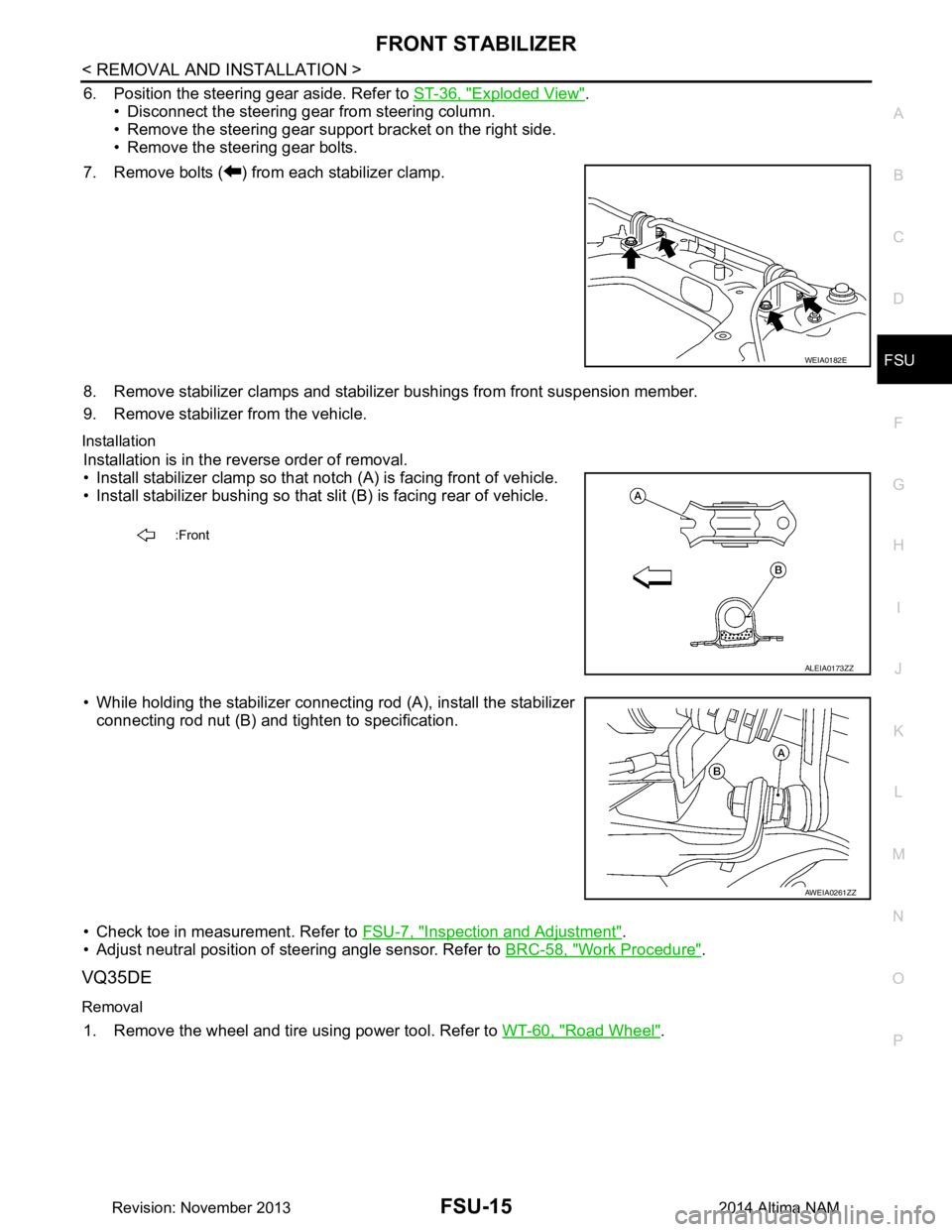
7. Remove bolts ( ) from each stabilizer clamp.
8. Remove stabilizer clamps and stabilizer bushings from front suspension member.
9. Remove stabilizer from the vehicle.
Installation
Installation is in the reverse order of removal.
• Install stabilizer clamp so that notch (A) is facing front of vehicle.
• Install stabilizer bushing so that slit (B) is facing rear of vehicle.
• While holding the stabilizer connecting rod (A), install the stabilizer connecting rod nut (B) and ti ghten to specification.
• Check toe in measurement. Refer to FSU-7, "Inspection and Adjustment"
.
• Adjust neutral position of steering angle sensor. Refer to BRC-58, "Work Procedure"
.
VQ35DE
Removal
1. Remove the wheel and tire using power tool. Refer to WT-60, "Road Wheel".
WEIA0182E
:Front
ALEIA0173ZZ
AWEIA0261ZZ
Revision: November 20132014 Altima NAM
Page 2519 of 4801
FSU-18
< REMOVAL AND INSTALLATION >
STEERING KNUCKLE
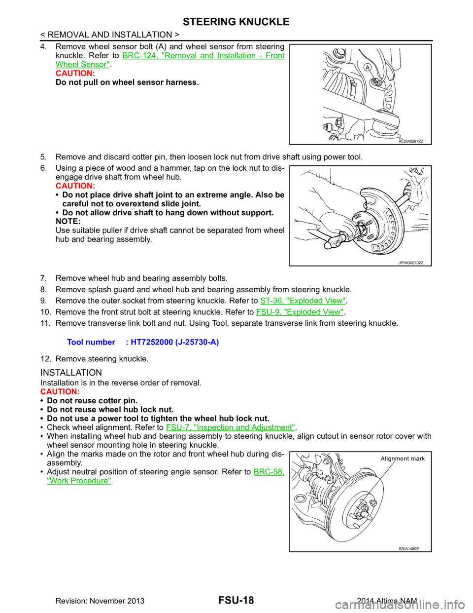
4. Remove wheel sensor bolt (A) and wheel sensor from steeringknuckle. Refer to BRC-124, "Removal and Installation - Front
Wheel Sensor".
CAUTION:
Do not pull on wheel sensor harness.
5. Remove and discard cotter pin, then loosen lock nut from drive shaft using power tool.
6. Using a piece of wood and a hammer, tap on the lock nut to dis- engage drive shaft from wheel hub.
CAUTION:
• Do not place drive shaft joint to an extreme angle. Also be
careful not to over extend slide joint.
• Do not allow drive shaft to hang down without support.
NOTE:
Use suitable puller if drive shaft cannot be separated from wheel
hub and bearing assembly.
7. Remove wheel hub and bearing assembly bolts.
8. Remove splash guard and wheel hub and bearing assembly from steering knuckle.
9. Remove the outer socket from steering knuckle. Refer to ST-36, "Exploded View"
.
10. Remove the front strut bolt at steering knuckle. Refer to FSU-9, "Exploded View"
.
11. Remove transverse link bolt and nut. Using Tool, separate transverse link from steering knuckle.
12. Remove steering knuckle.
INSTALLATION
Installation is in the reverse order of removal.
CAUTION:
• Do not reuse cotter pin.
• Do not reuse wheel hub lock nut.
• Do not use a power tool to tighten the wheel hub lock nut.
• Check wheel alignment. Refer to FSU-7, "Inspection and Adjustment"
.
• When installing wheel hub and bearing assembly to steering knuckle, align cutout in sensor rotor cover with
wheel sensor mounting hole in steering knuckle.
• Align the marks made on the rotor and front wheel hub during dis- assembly.
• Adjust neutral position of steering angle sensor. Refer to BRC-58,
"Work Procedure".
ALDIA0287ZZ
JPDIG0070ZZ
Tool number : HT7252000 (J-25730-A)
SDIA1480E
Revision: November 20132014 Altima NAM
Page 2521 of 4801
FSU-20
< UNIT REMOVAL AND INSTALLATION >
FRONT SUSPENSION ASSEMBLY
Removal and Installation
INFOID:0000000009460637
QR25DE ENGINE
Removal
1. Remove front wheel and tire using power tool. Refer to WT-55, "Adjustment".
2. Remove each brake caliper using power tool, leaving brake caliper hydraulic hose attached. Position each brake caliper aside with wire. Refer to BR-36, "BRAKE CALIPER ASSEMBLY : Exploded View"
.
CAUTION:
• Do not depress brake pedal while brake caliper is removed.
• Do not twist or stretch the brake hose.
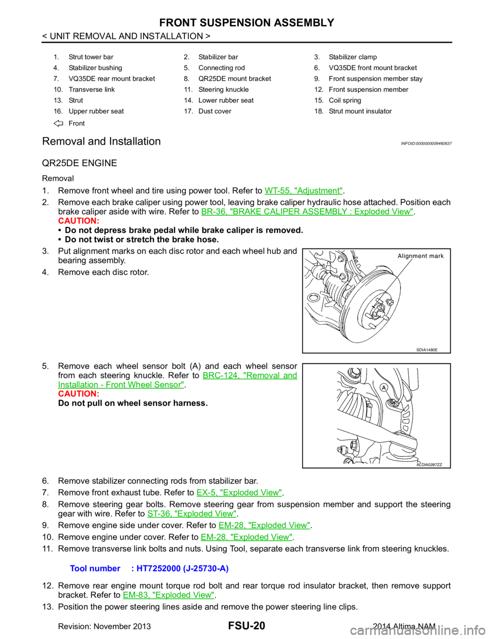
3. Put alignment marks on each disc rotor and each wheel hub and bearing assembly.
4. Remove each disc rotor.
5. Remove each wheel sensor bolt (A) and each wheel sensor from each steering knuckle. Refer to BRC-124, "Removal and
Installation - Front Wheel Sensor".
CAUTION:
Do not pull on wheel sensor harness.
6. Remove stabilizer connecting rods from stabilizer bar.
7. Remove front exhaust tube. Refer to EX-5, "Exploded View"
.
8. Remove steering gear bolts. Remove steering gear from suspension member and support the steering gear with wire. Refer to ST-36, "Exploded View"
.
9. Remove engine side under cover. Refer to EM-28, "Exploded View"
.
10. Remove engine under cover. Refer to EM-28, "Exploded View"
.
11. Remove transverse link bolts and nuts. Using Tool, separate each transverse link from steering knuckles.
12. Remove rear engine mount torque rod bolt and rear torque rod insulator bracket, then remove support bracket. Refer to EM-83, "Exploded View"
.
13. Position the power steering lines aside and remove the power steering line clips.
1. Strut tower bar 2. Stabilizer bar 3. Stabilizer clamp
4. Stabilizer bushing 5. Connecting rod 6. VQ35DE front mount bracket
7. VQ35DE rear mount bracket 8. QR25DE mount bracket 9. Front suspension member stay
10. Transverse link 11. Steering knuckle 12. Front suspension member
13. Strut 14. Lower rubber seat 15. Coil spring
16. Upper rubber seat 17. Dust cover 18. Strut mount insulator
Front
SDIA1480E
ALDIA0287ZZ
Tool number : HT7252000 (J-25730-A)
Revision: November 20132014 Altima NAM
Page 2522 of 4801
FRONT SUSPENSION ASSEMBLYFSU-21
< UNIT REMOVAL AND INSTALLATION >
C
D
F
G H
I
J
K L
M A
B
FSU
N
O P
14. Set Tool under suspension member, and remove suspension member bolts. Slowly lower Tool to remove suspension member from vehicle
15. If replacing suspension member, remove the following components from the suspension member. • transverse links.
• stabilizer bar.
• front suspension member stays.
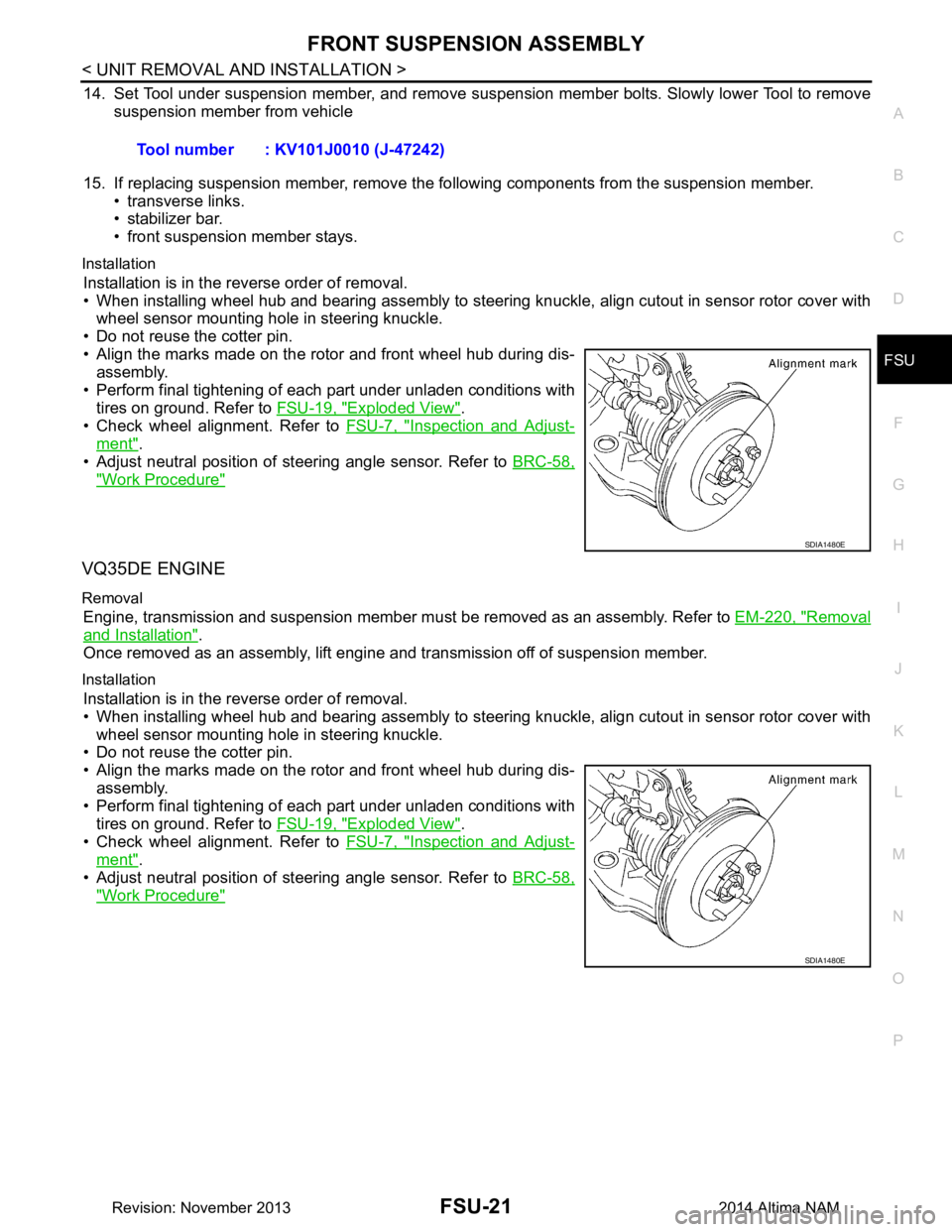
Installation
Installation is in the reverse order of removal.
• When installing wheel hub and bearing assembly to steering knuckle, align cutout in sensor rotor cover with wheel sensor mounting hole in steering knuckle.
• Do not reuse the cotter pin.
• Align the marks made on the rotor and front wheel hub during dis- assembly.
• Perform final tightening of each part under unladen conditions with tires on ground. Refer to FSU-19, "Exploded View"
.
• Check wheel alignment. Refer to FSU-7, "Inspection and Adjust-
ment".
• Adjust neutral position of steering angle sensor. Refer to BRC-58,
"Work Procedure"
VQ35DE ENGINE
Removal
Engine, transmission and suspension member must be removed as an assembly. Refer to EM-220, "Removal
and Installation".
Once removed as an assembly, lift engine and transmission off of suspension member.
Installation
Installation is in the reverse order of removal.
• When installing wheel hub and bearing assembly to steering knuckle, align cutout in sensor rotor cover with
wheel sensor mounting hole in steering knuckle.
• Do not reuse the cotter pin.
• Align the marks made on the rotor and front wheel hub during dis-
assembly.
• Perform final tightening of each part under unladen conditions with tires on ground. Refer to FSU-19, "Exploded View"
.
• Check wheel alignment. Refer to FSU-7, "Inspection and Adjust-
ment".
• Adjust neutral position of steering angle sensor. Refer to BRC-58,
"Work Procedure"
Tool number : KV101J0010 (J-47242)
SDIA1480E
SDIA1480E
Revision: November 20132014 Altima NAM
Page 2529 of 4801

GI-1
GENERAL INFORMATION
C
D E
F
G H
I
J
K L
M B
GI
SECTION GI
N
O P
CONTENTS
GENERAL INFORMATION
HOW TO USE THIS MANU AL ......................3
HOW TO USE THIS MANUAL ....................... .....3
Description .......................................................... ......3
Terms ........................................................................3
Units ..........................................................................3
Contents ....................................................................3
Relation between Illustrations and Descriptions .......4
Components ..............................................................4
HOW TO FOLLOW TROUBLE DIAGNOSES .....6
Description ................................................................6
How to Follow Test Groups in Trouble Diagnosis ......6
Key to Symbols Signifying Measurements or Pro-
cedures ............................................................... ......
7
HOW TO READ WIRING DIAGRAMS ................9
Connector symbols ............................................. ......9
Sample/wiring diagram -example- ...........................10
Description ..............................................................11
ABBREVIATIONS .......................................... ....13
Abbreviation List .................................................. ....13
TIGHTENING TORQUE OF STANDARD
BOLTS ............................................................ ....
18
Description .......................................................... ....18
Tightening Torque Table (New Standard Includ-
ed) ....................................................................... ....
18
RECOMMENDED CHEMICAL PRODUCTS
AND SEALANTS ............................................ ....
21
Recommended Chemical Products and Sealants ....21
VEHICLE INFORMATION ............................22
IDENTIFICATION INFORMATION ................. ....22
Model Variation ................................................... ....22
Identification Number ..............................................23
Identification Plate ...................................................24
Engine Serial Number .............................................24
CVT Number ...........................................................25
Dimensions .......................................................... ....25
Wheels & Tires ........................................................25
PRECAUTION ..............................................26
PRECAUTIONS .................................................26
Description ........................................................... ....26
Precaution for Supplemental Restraint System
(SRS) "AIR BAG" and "SEAT BELT PRE-TEN-
SIONER" ............................................................. ....
26
Precautions For Xenon Headlamp Service .............26
Procedures without Cowl Top Cover .......................27
Cautions in Removing Battery Terminal and AV
Control Unit .......................................................... ....
27
General Precautions ................................................27
Three Way Catalyst .................................................29
Fuel (Regular Unleaded Gasoline Recommend-
ed) QR25DE ........................................................ ....
29
Fuel (Regular Unleaded Gasoline Recommend-
ed) VQ35DE ........................................................ ....
29
Multiport Fuel Injection System or Engine Control
System ................................................................. ....
29
Hoses ......................................................................29
Engine Oils ..............................................................30
Air Conditioning .......................................................31
LIFTING POINT .................................................32
Special Service Tool ................................................32
Pantograph Jack ......................................................32
Garage Jack and Safety Stand ................................33
2-Pole Lift ................................................................34
Board-on Lift ............................................................35
TOW TRUCK TOWING .....................................36
Tow Truck Towing ...................................................36
Vehicle Recovery (Freeing a Stuck Vehicle) ...........36
WIRING DIAGRAM ......................................38
CONSULT CHECKING SYSTEM .....................38
Wiring Diagram .................................................... ....38
Revision: November 20132014 Altima NAMRevision: November 20132014 Altima NAM
Page 3166 of 4801
![NISSAN TEANA 2014 Service Manual
LU-16
< REMOVAL AND INSTALLATION >[QR25DE]
OIL COOLER
OIL COOLER
Exploded ViewINFOID:0000000009461035
Removal and InstallationINFOID:0000000009461036
WARNING:
Be careful not to burn yourself, as eng NISSAN TEANA 2014 Service Manual
LU-16
< REMOVAL AND INSTALLATION >[QR25DE]
OIL COOLER
OIL COOLER
Exploded ViewINFOID:0000000009461035
Removal and InstallationINFOID:0000000009461036
WARNING:
Be careful not to burn yourself, as eng](/manual-img/5/57390/w960_57390-3165.png)
LU-16
< REMOVAL AND INSTALLATION >[QR25DE]
OIL COOLER
OIL COOLER
Exploded ViewINFOID:0000000009461035
Removal and InstallationINFOID:0000000009461036
WARNING:
Be careful not to burn yourself, as engi ne oil and engine coolant may be hot.
NOTE:
When removing components such as hoses, tubes/lines, etc. , cap or plug openings to prevent fluid from spill-
ing.
REMOVAL
1. Remove RH front road wheel and tire. Refer to WT-55, "Adjustment".
2. Remove RH fender protector. Refer to EXT-26, "FENDER PROTECTOR : Removal and Installation"
.
3. Drain engine coolant by removing water drain plug on cylinder block and radiator drain plug. Refer to CO-
12, "Changing Engine Coolant".
4. Disconnect hoses from the oil cooler.
5. Remove oil cooler bolts in reverse numerical order.
6. Remove oil cooler.
7. Remove relief valve and O-rings.
INSTALLATION
Installation is in the reverse order of removal.
CAUTION:
1-5. Tightening sequence 6. O-ring 7. Relief Valve
8. Oil cooler A. To water hose
AWBIA1295GB
Revision: November 20132014 Altima NAM
Page 3228 of 4801
MA-44
< PERIODIC MAINTENANCE >
CHASSIS AND BODY MAINTENANCE
POWER STEERING FLUID AND LINES : Inspection
INFOID:0000000009464588
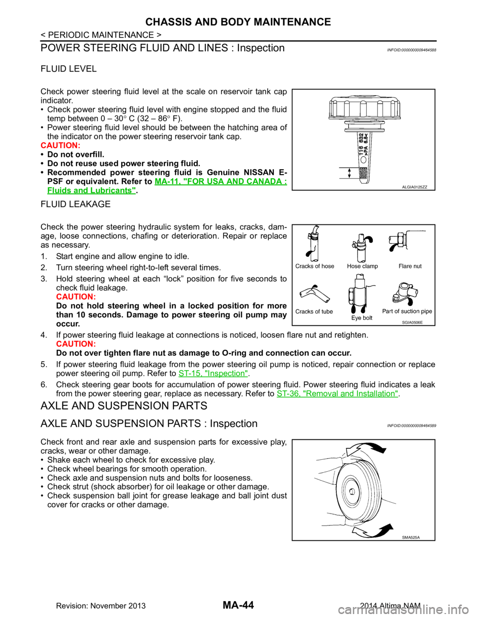
FLUID LEVEL
Check power steering fluid level at the scale on reservoir tank cap
indicator.
• Check power steering fluid level with engine stopped and the fluid temp between 0 – 30 ° C (32 – 86 ° F).
• Power steering fluid level should be between the hatching area of the indicator on the power steering reservoir tank cap.
CAUTION:
• Do not overfill.
• Do not reuse used power steering fluid.
• Recommended power steering fluid is Genuine NISSAN E-
PSF or equivalent. Refer to MA-11, "FOR USA AND CANADA :
Fluids and Lubricants".
FLUID LEAKAGE
Check the power steering hydraulic system for leaks, cracks, dam-
age, loose connections, chafing or det erioration. Repair or replace
as necessary.
1. Start engine and allow engine to idle.
2. Turn steering wheel right-to-left several times.
3. Hold steering wheel at each “lock” position for five seconds to check fluid leakage.
CAUTION:
Do not hold steering wheel in a locked position for more
than 10 seconds. Damage to power steering oil pump may
occur.
4. If power steering fluid leakage at connections is noticed, loosen flare nut and retighten.
CAUTION:
Do not over tighten flare nut as damage to O-ring and connection can occur.
5. If power steering fluid leakage from the power steer ing oil pump is noticed, repair connection or replace
power steering oil pump. Refer to ST-15, "Inspection"
.
6. Check steering gear boots for accumulation of power steering fluid. Power steering fluid indicates a leak from the power steering gear, replace as necessary. Refer to ST-36, "Removal and Installation"
.
AXLE AND SUSPENSION PARTS
AXLE AND SUSPENSION PARTS : InspectionINFOID:0000000009464589
Check front and rear axle and suspension parts for excessive play,
cracks, wear or other damage.
• Shake each wheel to check for excessive play.
• Check wheel bearings for smooth operation.
• Check axle and suspension nuts and bolts for looseness.
• Check strut (shock absorber) for oil leakage or other damage.
• Check suspension ball joint for grease leakage and ball joint dust cover for cracks or other damage.
ALGIA0125ZZ
SGIA0506E
SMA525A
Revision: November 20132014 Altima NAM