2014 NISSAN TEANA wheel bolts
[x] Cancel search: wheel boltsPage 3968 of 4801
SR-6
< BASIC INSPECTION >
COLLISION DIAGNOSIS
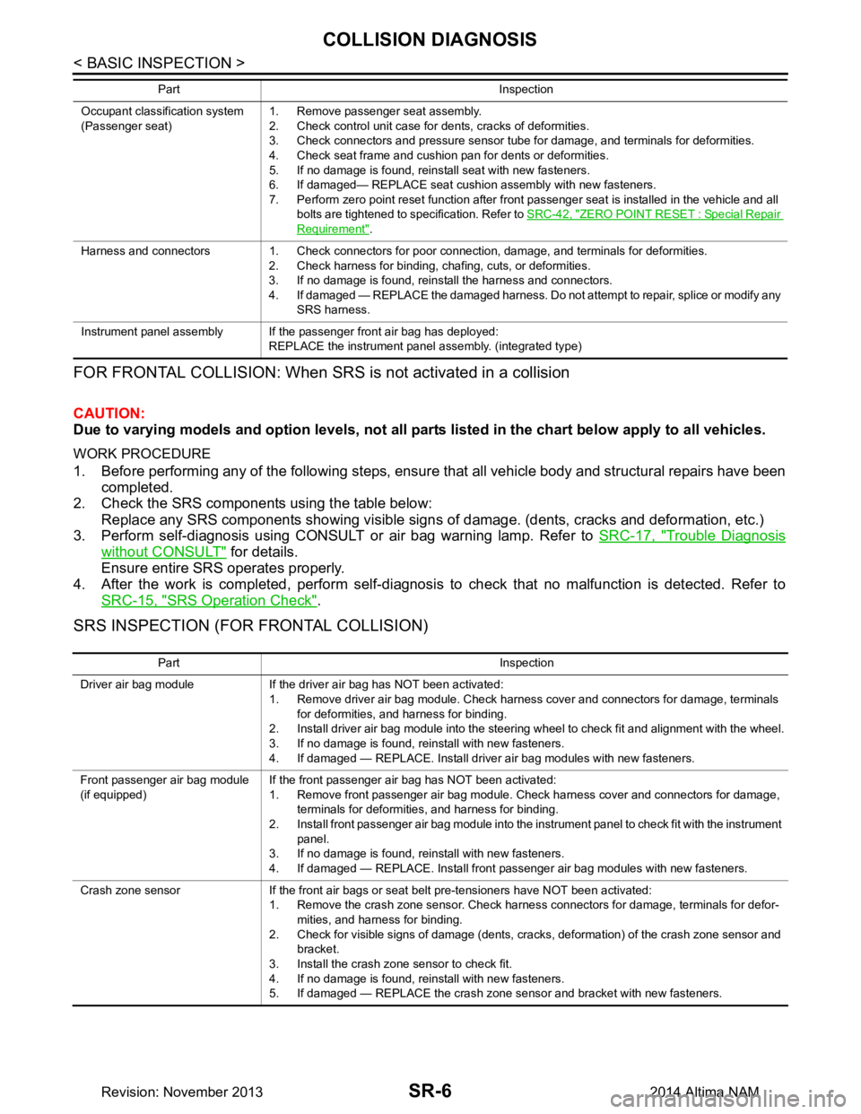
FOR FRONTAL COLLISION: When SRS is not activated in a collision
CAUTION:
Due to varying models and option levels, not all part s listed in the chart below apply to all vehicles.
WORK PROCEDURE
1. Before performing any of the following steps, ensur e that all vehicle body and structural repairs have been
completed.
2. Check the SRS components using the table below:
Replace any SRS components showing visible signs of damage. (dents, cracks and deformation, etc.)
3. Perform self-diagnosis using CONSULT or air bag warning lamp. Refer to SRC-17, "Trouble Diagnosis
without CONSULT" for details.
Ensure entire SRS operates properly.
4. After the work is completed, perform self-diagnosis to check that no malfunction is detected. Refer to
SRC-15, "SRS Operation Check"
.
SRS INSPECTION (FOR FRONTAL COLLISION)
Occupant classification system
(Passenger seat) 1. Remove passenger seat assembly.
2. Check control unit case for dents, cracks of deformities.
3. Check connectors and pressure sensor tube for damage, and terminals for deformities.
4. Check seat frame and cushion pan for dents or deformities.
5. If no damage is found, reinstall seat with new fasteners.
6. If damaged— REPLACE seat cushion assembly with new fasteners.
7. Perform zero point reset function after front passenger seat is installed in the vehicle and all bolts are tightened to specification. Refer to SRC-42, "ZERO POINT RESET : Special Repair
Requirement".
Harness and connectors 1. Check connectors for poor connection, damage, and terminals for deformities. 2. Check harness for binding, chafing, cuts, or deformities.
3. If no damage is found, reinstall the harness and connectors.
4. If damaged — REPLACE the damaged harness. Do not attempt to repair, splice or modify any SRS harness.
Instrument panel assembly If the passenger front air bag has deployed: REPLACE the instrument panel assembly. (integrated type)
Part Inspection
Part Inspection
Driver air bag module If the driver air bag has NOT been activated: 1. Remove driver air bag module. Check harness cover and connectors for damage, terminals for deformities, and harness for binding.
2. Install driver air bag module into the steering wheel to check fit and alignment with the wheel.
3. If no damage is found, reinstall with new fasteners.
4. If damaged — REPLACE. Install driver air bag modules with new fasteners.
Front passenger air bag module
(if equipped) If the front passenger air bag has NOT been activated:
1. Remove front passenger air bag module. Check harness cover and connectors for damage, terminals for deformities, and harness for binding.
2. Install front passenger air bag module into the instrument panel to check fit with the instrument panel.
3. If no damage is found, reinstall with new fasteners.
4. If damaged — REPLACE. Install front passenger air bag modules with new fasteners.
Crash zone sensor If the front air bags or seat belt pre-tensioners have NOT been activated: 1. Remove the crash zone sensor. Check harness connectors for damage, terminals for defor-mities, and harness for binding.
2. Check for visible signs of damage (dents, cracks, deformation) of the crash zone sensor and bracket.
3. Install the crash zone sensor to check fit.
4. If no damage is found, reinstall with new fasteners.
5. If damaged — REPLACE the crash zone sensor and bracket with new fasteners.
Revision: November 20132014 Altima NAM
Page 3969 of 4801
COLLISION DIAGNOSISSR-7
< BASIC INSPECTION >
C
D E
F
G
I
J
K L
M A
B
SR
N
O P
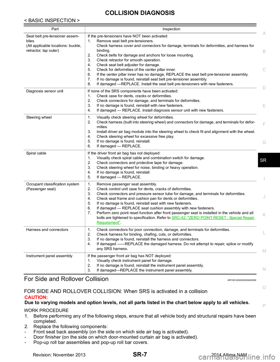
For Side and Rollover CollisionINFOID:0000000009463068
FOR SIDE AND ROLLOVER COLLISION: When SRS is activated in a collision
CAUTION:
Due to varying models and option levels, not all parts listed in the chart below apply to all vehicles.
WORK PROCEDURE
1. Before performing any of the following steps, ensur e that all vehicle body and structural repairs have been
completed.
2. Replace the following components:
- Front seat back assembly (on the side on which side air bag is activated).
- Door finisher (on the side on which door-mounted curtain air bag is activated).
- Pop-up roll bar assemblies and pop-up roll bar covers.
Seat belt pre-tensioner assem-
blies
(All applicable locations: buckle,
retractor, lap outer) If the pre-tensioners have NOT been activated:
1. Remove seat belt pre-tensioners.
Check harness cover and connectors for damage, terminals for deformities, and harness for
binding.
2. Check belts for damage and anchors for loose mounting.
3. Check retractor for smooth operation.
4. Check seat belt adjuster for damage.
5. Check for deformities of the center pillar inner.
6. If the center pillar inner has no damage, REPLACE the seat belt pre-tensioner assembly.
7. If no damage is found, reinstall seat belt pre-tensioner assembly.
8. If damaged —REPLACE. Install the seat belt pre-tensioners with new fasteners.
Diagnosis sensor unit If none of the SRS components have been activated: 1. Check case for dents, cracks or deformities.
2. Check connectors for damage, and terminals for deformities.
3. If no damage is found, reinstall with new fasteners.
4. If damaged — REPLACE. Install diagnosis sensor unit with new fasteners.
Steering wheel 1. Visually check steering wheel for deformities. 2. Check harness (built into steering wheel) and connectors for damage, and terminals for defor-mities.
3. Install driver air bag module into the steering wheel to check fit and alignment with the wheel.
4. Check steering wheel for excessive free play.
5. If no damage is found, reinstall.
6. If damaged — REPLACE.
Spiral cable If the driver front air bag has not deployed: 1. Visually check spiral cable and combination switch for damage.
2. Check connectors and protective tape for damage.
3. Check steering wheel for noise, binding or heavy operation.
4. If no damage is found, reinstall.
5. If damaged — REPLACE.
Occupant classification system
(Passenger seat) 1. Remove passenger seat assembly.
2. Check control unit case for dents, cracks of deformities.
3. Check connectors and pressure sensor tube for damage, and terminals for deformities.
4. Check seat frame and cushion pan for dents or deformities.
5. If no damage is found, reinstall seat with new fasteners.
6. If damaged — REPLACE seat cushion assembly with new fasteners.
7. Perform zero point reset function after front passenger seat is installed in the vehicle and all
bolts are tightened to specification. Refer to SRC-42, "ZERO POINT RESET : Special Repair
Requirement".
Harness and connectors 1. Check connectors for poor connection, damage, and terminals for deformities. 2. Check harness for binding, chafing, cuts, or deformities.
3. If no damage is found, reinstall the harness and connectors.
4. If damaged ——REPLACE the damaged harness. Do not attempt to repair, splice or modify any SRS harness.
Instrument panel assembly If the passenger front air bag has NOT deployed: 1. Visually check instrument panel for damage.
2. If no damage is found, reinstall the instrument panel assembly.
3. If damaged—REPLACE the instrument panel assembly.
Part Inspection
Revision: November 20132014 Altima NAM
Page 4109 of 4801
ST-6
< PREPARATION >
PREPARATION
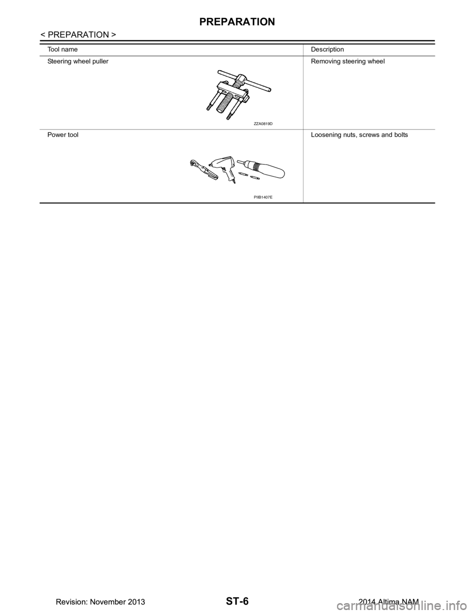
Tool nameDescription
Steering wheel puller Removing steering wheel
Power tool Loosening nuts, screws and bolts
ZZA0819D
PIIB1407E
Revision: November 20132014 Altima NAMRevision: November 20132014 Altima NAM
Page 4140 of 4801
STEERING GEAR AND LINKAGEST-37
< REMOVAL AND INSTALLATION >
C
D E
F
H I
J
K L
M A
B
ST
N
O P
6. Remove front exhaust tube. Refer to EX-5, "Exploded View" (QR25DE), EX-10, "Exploded View"
(VQ35DE).
7. Disconnect the high and low pressure piping from the steering gear assembly.
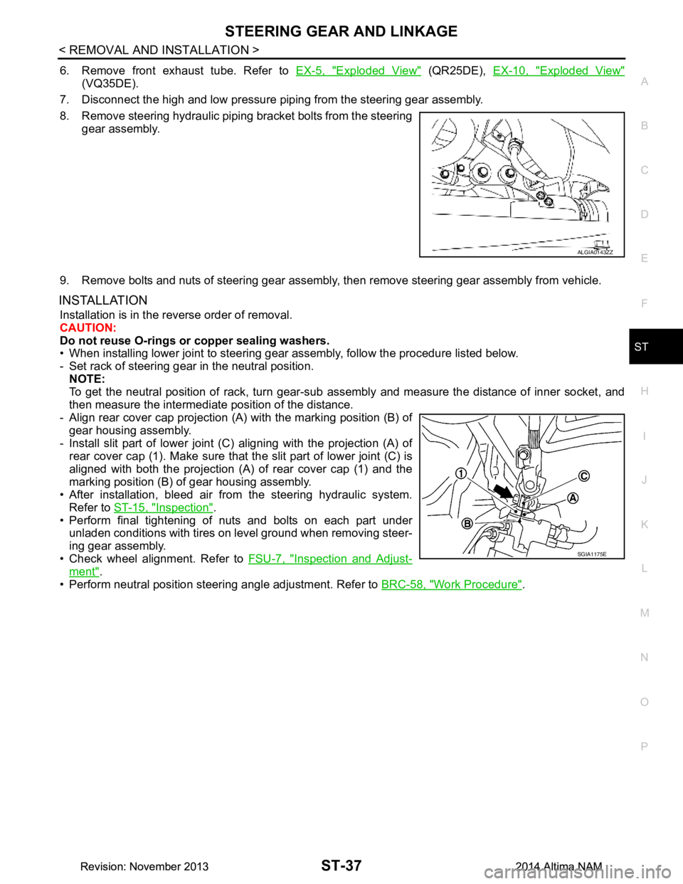
8. Remove steering hydraulic piping bracket bolts from the steering gear assembly.
9. Remove bolts and nuts of steering gear assembly, then remove steering gear assembly from vehicle.
INSTALLATION
Installation is in the reverse order of removal.
CAUTION:
Do not reuse O-rings or copper sealing washers.
• When installing lower joint to steering gear assembly, follow the procedure listed below.
- Set rack of steering gear in the neutral position. NOTE:
To get the neutral position of rack, turn gear-sub a ssembly and measure the distance of inner socket, and
then measure the intermediat e position of the distance.
- Align rear cover cap projection (A) with the marking position (B) of
gear housing assembly.
- Install slit part of lower joint (C) aligning with the projection (A) of
rear cover cap (1). Make sure that the slit part of lower joint (C) is
aligned with both the projection (A) of rear cover cap (1) and the
marking position (B) of gear housing assembly.
• After installation, bleed air from the steering hydraulic system. Refer to ST-15, "Inspection"
.
• Perform final tightening of nuts and bolts on each part under
unladen conditions with tires on level ground when removing steer-
ing gear assembly.
• Check wheel alignment. Refer to FSU-7, "Inspection and Adjust-
ment".
• Perform neutral position steering angle adjustment. Refer to BRC-58, "Work Procedure"
.
ALGIA0143ZZ
SGIA1175E
Revision: November 20132014 Altima NAMRevision: November 20132014 Altima NAM
Page 4154 of 4801
PRECAUTIONSSTC-3
< PRECAUTION >
C
D E
F
H I
J
K L
M A
B
STC
N
O P
PRECAUTION
PRECAUTIONS
Precaution for Supplemental Restraint System (SRS) "AIR BAG" and "SEAT BELT
PRE-TENSIONER"
INFOID:0000000009951730
The Supplemental Restraint System such as “A IR BAG” and “SEAT BELT PRE-TENSIONER”, used along
with a front seat belt, helps to reduce the risk or severi ty of injury to the driver and front passenger for certain
types of collision. Information necessary to service t he system safely is included in the SR and SB section of
this Service Manual.
WARNING:
• To avoid rendering the SRS inoper ative, which could increase the risk of personal injury or death in
the event of a collision which would result in air bag inflation, all maintenance must be performed by
an authorized NISSAN/INFINITI dealer.
• Improper maintenance, including in correct removal and installation of the SRS, can lead to personal
injury caused by unintentional act ivation of the system. For removal of Spiral Cable and Air Bag
Module, see the SR section.
• Do not use electrical test equipm ent on any circuit related to the SRS unless instructed to in this
Service Manual. SRS wiring harnesses can be identi fied by yellow and/or orange harnesses or har-
ness connectors.
PRECAUTIONS WHEN USING POWER TOOLS (AIR OR ELECTRIC) AND HAMMERS
WARNING:
• When working near the Airbag Diagnosis Sensor Un it or other Airbag System sensors with the Igni-
tion ON or engine running, DO NOT use air or el ectric power tools or strike near the sensor(s) with a
hammer. Heavy vibration could activate the sensor( s) and deploy the air bag(s), possibly causing
serious injury.
• When using air or electric power tools or hammers , always switch the Ignition OFF, disconnect the
battery and wait at least three mi nutes before performing any service.
Service Notice and Precautions for Hydrau lic Pump Electric Power Steering System
INFOID:0000000009460340
• Check each tire for proper air pressure and size. Refer to WT-60, "Tire".
• Verify that the steering system components are G enuine NISSAN parts and have been installed properly.
• Check the steering column for loose mounting bolts.
• Check the steering gear assembly for loose mounting bolts. Check the inner sockets and outer sockets for
damage or wear. Inspect the boots and seals for leakage of power steering fluid.
• Verify proper wheel alignment. Refer to FSU-7, "Inspection and Adjustment"
.
• Check for any damage, wear, or modification to the suspension and body that would result in increased
weight or an improper wheelarch height. Refer to FSU-26, "Wheelarch Height (Unladen*
1)".
• Check for proper battery voltage.
• Verify that all power steering pump assembly connections are clean and fully seated.
• Verify that only Genuine NISSAN E-PSF is used. Use of any power steering fluid other than Genuine NIS-
SAN E-PSF will prevent the power st eering system from proper operation.
• An audible high pitch noise may be heard from the engine compartment when the steering wheel is oper-
ated, particularly at low speeds such as a parking lot maneuver. This condition is not a malfunction, rather
normal system operation. Steering at low speeds or parking lot maneuvers demands higher hydraulic assis-
tance, resulting in larger power st eering pump load and increased system noise.
• The power steering pump is electrically controlled by the power steering control module.
• Before connecting or disconnecting the power steeri ng control module harness connectors, turn ignition
switch “OFF” and disconnect battery ground cable. Batter y voltage is applied to power steering control mod-
ule even if ignition switch is turned “OFF”.
Revision: November 20132014 Altima NAMRevision: November 20132014 Altima NAM