2014 NISSAN TEANA wheel bolts
[x] Cancel search: wheel boltsPage 2220 of 4801
![NISSAN TEANA 2014 Service Manual
EM-222
< UNIT REMOVAL AND INSTALLATION >[VQ35DE]
ENGINE ASSEMBLY
• (B): LH cylinder head
25. Remove rear cover plate.
26. Remove the torque converter nuts.
27. Remove nuts of stabilizer connectin NISSAN TEANA 2014 Service Manual
EM-222
< UNIT REMOVAL AND INSTALLATION >[VQ35DE]
ENGINE ASSEMBLY
• (B): LH cylinder head
25. Remove rear cover plate.
26. Remove the torque converter nuts.
27. Remove nuts of stabilizer connectin](/manual-img/5/57390/w960_57390-2219.png)
EM-222
< UNIT REMOVAL AND INSTALLATION >[VQ35DE]
ENGINE ASSEMBLY
• (B): LH cylinder head
25. Remove rear cover plate.
26. Remove the torque converter nuts.
27. Remove nuts of stabilizer connecting rods from struts. Refer to FSU-19, "Exploded View"
.
28. Remove front wheel speed sensors and position aside. Refer to BRC-124, "Removal and Installation -
Front Wheel Sensor".
29. Remove front brake rotors. Refer to BR-36, "BRAKE CALIPER ASSEMBLY : Removal and Installation"
.
30. Remove piston rod nut. Refer to FSU-19, "Exploded View"
.
31. Remove front drive shaft (LH/RH). Refer to FAX-10, "Removal and Installation (LH)"
and FAX-12,
"Removal and Installation (RH)".
32. Remove RH drive shaft center bearing bracket.
33. Remove lower steering column pinch bolt. Refer to ST-33, "Exploded View"
.
34. Remove three way catalyst (manifold) (bank 1) heat shield.
35. Disconnect front and rear engine mounting insulator vacuum hoses.
36. Remove front and rear engine mounting insulator nut.
37. Position a suitable support table under suspension member and engine assembly. TM-206, "Removal and
Installation"
38. Disconnect the engine mounting insulator (LH), upper torque rod, and engine mounting insulator (RH).
39. For additional safety, secure the engine in position with suitable tool.
40. Remove suspension member bolts. Refer to FSU-19, "Exploded View"
.
41. Carefully lower the engine, transaxle assembly and suspension member using Tool, avoiding interference
with the vehicle body.
CAUTION:
• Before and during this procedure, alw ays check if any harnesses are left connected.
• Avoid any damage to, or any oil/grease smearin g or spilling onto the engine mounting insula-
tors.
42. Remove the starter motor. Refer to STR-23, "VQ35DE : Removal and Installation"
.
43. Remove the crankshaft position sensor (POS).
44. Remove engine and transaxle harness.
45. Separate the engine and transaxle and mount the engine on a suitable engine stand.
INSTALLATION
Installation is in the reverse order of removal.
NOTE:
Tighten transmission bolts to specification. Refer to TM-206, "Removal and Installation"
.
INSPECTION AFTER INSTALLATION
• Before starting engine, check oil/fluid levels including engine coolant and engine oil. If less than required
quantity, fill to the specified level. Refer to MA-11, "FOR USA AND CANADA : Fluids and Lubricants"
.
• Use procedure below to check for fuel leakage.
• Turn ignition switch ON (with engine stopped). With fuel pressure applied to fuel piping, check for fuel leak-
age at connection points.
ALBIA0263GB
Tool number : KV101J0010 (J-47242)
Revision: November 20132014 Altima NAM
Page 2461 of 4801
FRONT WHEEL HUBFAX-9
< REMOVAL AND INSTALLATION >
CEF
G H
I
J
K L
M A
B
FA X
N
O P
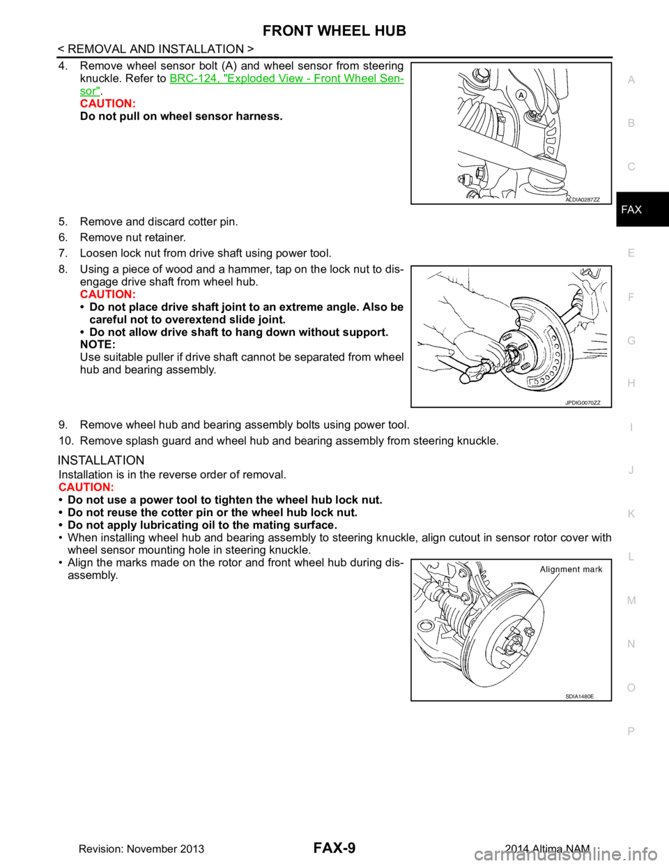
4. Remove wheel sensor bolt (A) and wheel sensor from steering knuckle. Refer to BRC-124, "Exploded View - Front Wheel Sen-
sor".
CAUTION:
Do not pull on wheel sensor harness.
5. Remove and discard cotter pin.
6. Remove nut retainer.
7. Loosen lock nut from drive shaft using power tool.
8. Using a piece of wood and a hammer, tap on the lock nut to dis- engage drive shaft from wheel hub.
CAUTION:
• Do not place drive shaft joint to an extreme angle. Also be careful not to over extend slide joint.
• Do not allow drive shaft to hang down without support.
NOTE:
Use suitable puller if drive shaft cannot be separated from wheel
hub and bearing assembly.
9. Remove wheel hub and bearing assembly bolts using power tool.
10. Remove splash guard and wheel hub and bearing assembly from steering knuckle.
INSTALLATION
Installation is in the reverse order of removal.
CAUTION:
• Do not use a power tool to tighten the wheel hub lock nut.
• Do not reuse the cotter pin or the wheel hub lock nut.
• Do not apply lubricating oil to the mating surface.
• When installing wheel hub and bearing assembly to steering knuckle, align cutout in sensor rotor cover with wheel sensor mounting hole in steering knuckle.
• Align the marks made on the rotor and front wheel hub during dis- assembly.
ALDIA0287ZZ
JPDIG0070ZZ
SDIA1480E
Revision: November 20132014 Altima NAM
Page 2462 of 4801
FAX-10
< REMOVAL AND INSTALLATION >
FRONT DRIVE SHAFT
FRONT DRIVE SHAFT
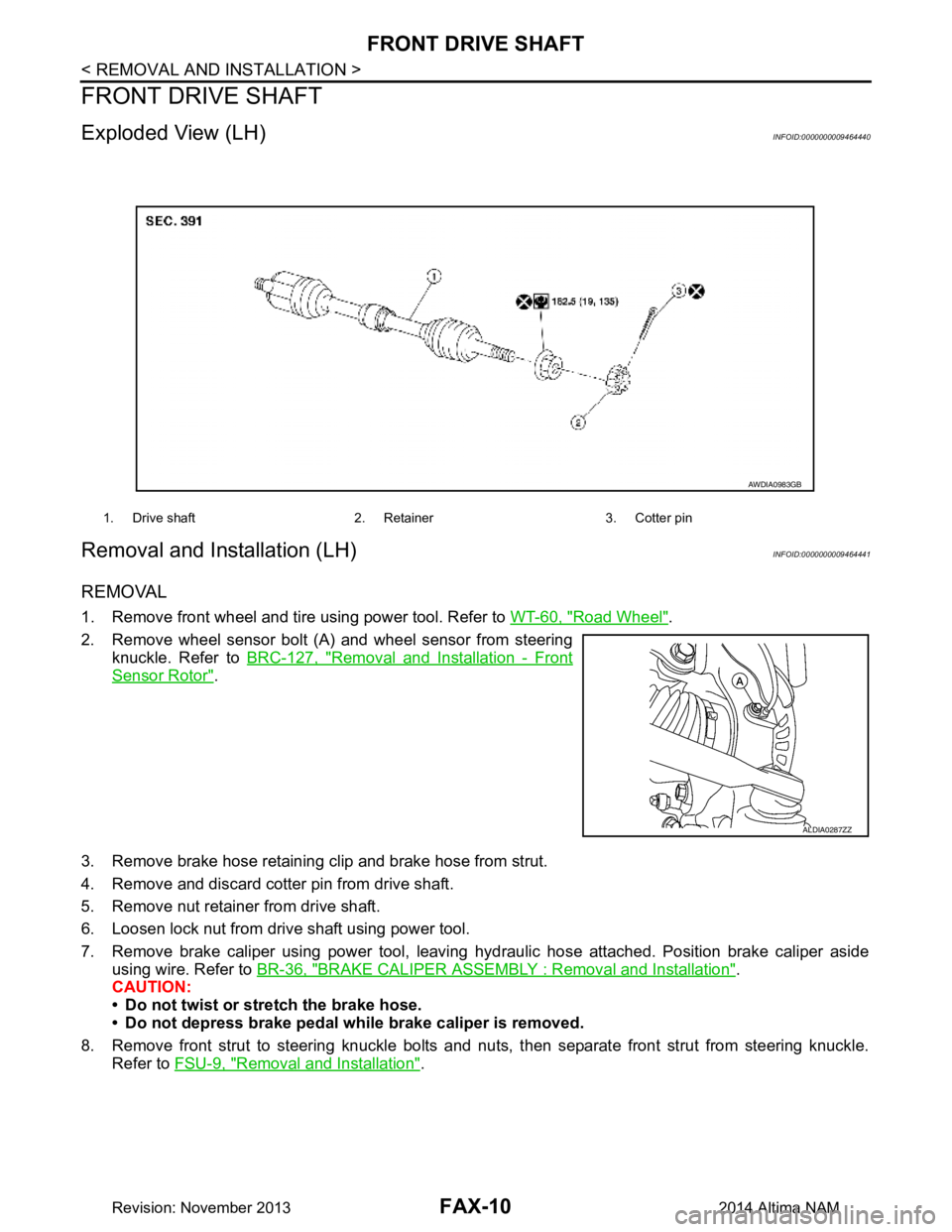
Exploded View (LH)INFOID:0000000009464440
Removal and Installation (LH)INFOID:0000000009464441
REMOVAL
1. Remove front wheel and tire using power tool. Refer to WT-60, "Road Wheel".
2. Remove wheel sensor bolt (A) and wheel sensor from steering knuckle. Refer to BRC-127, "Removal and Installation - Front
Sensor Rotor".
3. Remove brake hose retaining clip and brake hose from strut.
4. Remove and discard cotter pin from drive shaft.
5. Remove nut retainer from drive shaft.
6. Loosen lock nut from drive shaft using power tool.
7. Remove brake caliper using power tool, leaving hy draulic hose attached. Position brake caliper aside
using wire. Refer to BR-36, "BRAKE CALIPER ASSEMBLY : Removal and Installation"
.
CAUTION:
• Do not twist or stretch the brake hose.
• Do not depress brake pedal while brake caliper is removed.
8. Remove front strut to steering knuckle bolts and nut s, then separate front strut from steering knuckle.
Refer to FSU-9, "Removal and Installation"
.
1. Drive shaft 2. Retainer 3. Cotter pin
AWDIA0983GB
ALDIA0287ZZ
Revision: November 20132014 Altima NAM
Page 2465 of 4801
FRONT DRIVE SHAFTFAX-13
< REMOVAL AND INSTALLATION >
CEF
G H
I
J
K L
M A
B
FA X
N
O P
3. Remove brake hose retaining clip and brake hose from strut.
4. Remove and discard cotter pin from drive shaft.
5. Remove nut retainer from drive shaft.
6. Loosen lock nut from drive shaft using power tool.
7. Remove brake caliper using power tool, leaving hy draulic brake hose attached. Position caliper aside
using wire. Refer to BR-36, "BRAKE CALIPER ASSEMBLY : Removal and Installation"
.
CAUTION:
• Do not twist or stretch the brake hose.
• Do not depress brake pedal while brake caliper is removed.
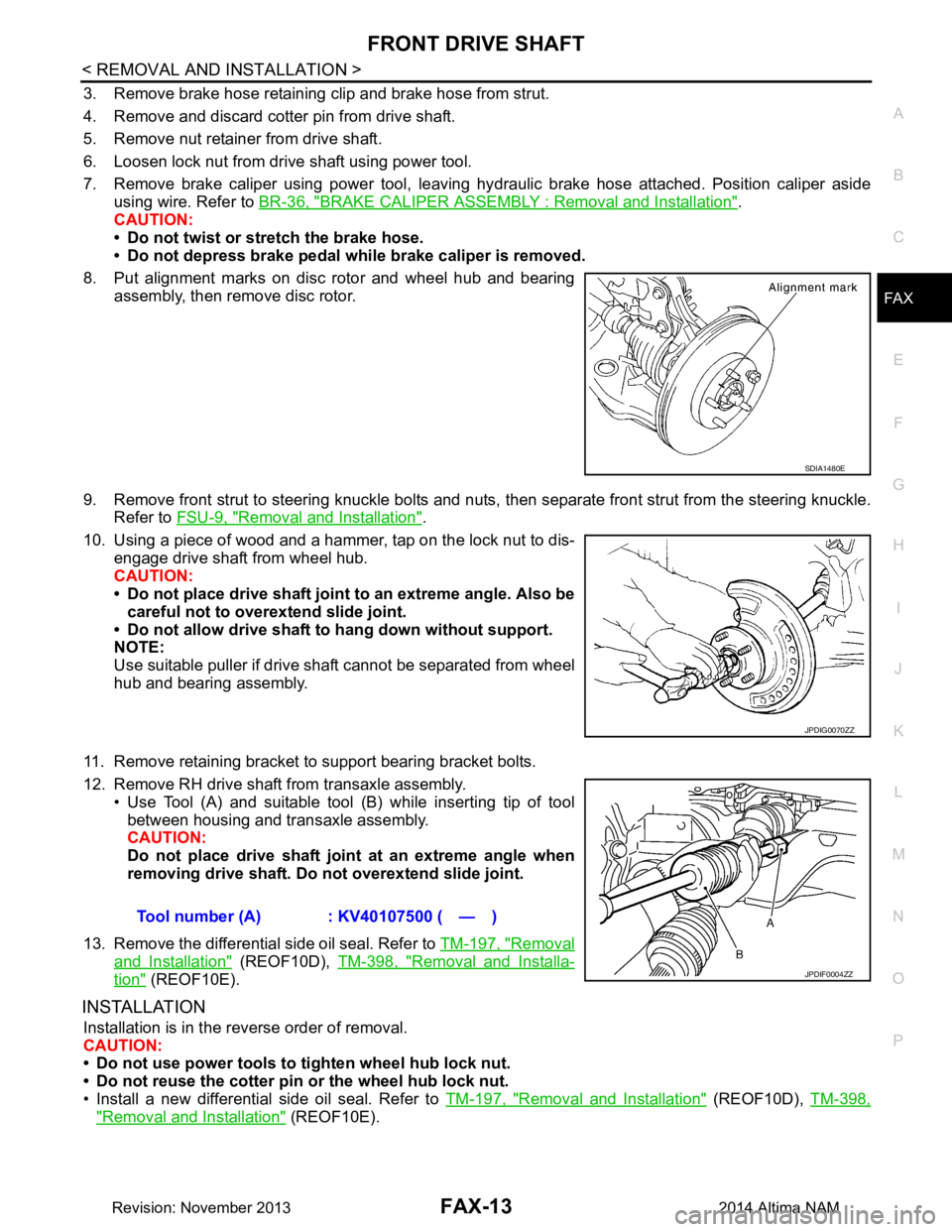
8. Put alignment marks on disc rotor and wheel hub and bearing assembly, then remove disc rotor.
9. Remove front strut to steering knuckle bolts and nuts, then separate front strut from the steering knuckle.
Refer to FSU-9, "Removal and Installation"
.
10. Using a piece of wood and a hammer, tap on the lock nut to dis- engage drive shaft from wheel hub.
CAUTION:
• Do not place drive shaft joint to an extreme angle. Also be careful not to over extend slide joint.
• Do not allow drive shaft to hang down without support.
NOTE:
Use suitable puller if drive shaft cannot be separated from wheel
hub and bearing assembly.
11. Remove retaining bracket to support bearing bracket bolts.
12. Remove RH drive shaft from transaxle assembly. • Use Tool (A) and suitable tool (B) while inserting tip of tool
between housing and transaxle assembly.
CAUTION:
Do not place drive shaft join t at an extreme angle when
removing drive shaft. Do not overextend slide joint.
13. Remove the differential side oil seal. Refer to TM-197, "Removal
and Installation" (REOF10D), TM-398, "Removal and Installa-
tion" (REOF10E).
INSTALLATION
Installation is in the reverse order of removal.
CAUTION:
• Do not use power tools to tighten wheel hub lock nut.
• Do not reuse the cotter pin or the wheel hub lock nut.
• Install a new differential side oil seal. Refer to TM-197, "Removal and Installation"
(REOF10D), TM-398,
"Removal and Installation" (REOF10E).
SDIA1480E
JPDIG0070ZZ
Tool number (A) : KV40107500 ( — )
JPDIF0004ZZ
Revision: November 20132014 Altima NAM
Page 2492 of 4801
FL-12
< REMOVAL AND INSTALLATION >
FUEL TANK
8. Remove rear wheel and tire using power tool. Refer to WT-55, "Adjustment".
9. Remove rear brake pads. Refer to BR-38, "BRAKE PAD : Removal and Installation"
.
10. Remove rear torque members and rear disc brake rotor.
11. Disconnect rear parking brake shoe, and remove rear cables from toggle lever. Refer to PB-9, "Removal
and Installation".
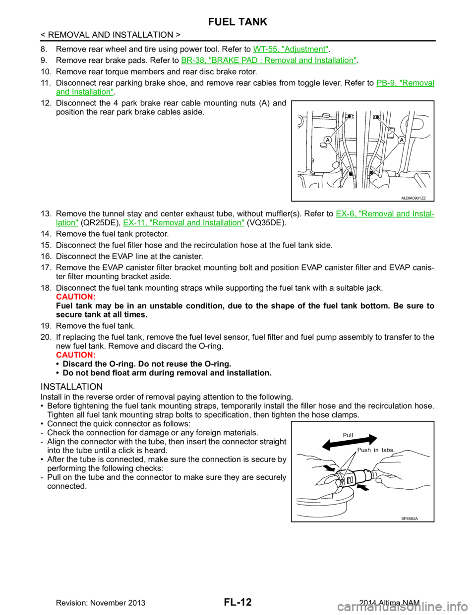
12. Disconnect the 4 park brake rear cable mounting nuts (A) and position the rear park brake cables aside.
13. Remove the tunnel stay and center exhaust tube, without muffler(s). Refer to EX-6, "Removal and Instal-
lation" (QR25DE), EX-11, "Removal and Installation" (VQ35DE).
14. Remove the fuel tank protector.
15. Disconnect the fuel filler hose and the recirculation hose at the fuel tank side.
16. Disconnect the EVAP line at the canister.
17. Remove the EVAP canister filter bracket mounti ng bolt and position EVAP canister filter and EVAP canis-
ter filter mounting bracket aside.
18. Disconnect the fuel tank mounting straps while supporting the fuel tank with a suitable jack. CAUTION:
Fuel tank may be in an unstable condition, due to the shape of the fuel tank bottom. Be sure to
secure tank at all times.
19. Remove the fuel tank.
20. If replacing the fuel tank, remove the fuel level sens or, fuel filter and fuel pump assembly to transfer to the
new fuel tank. Remove and discard the O-ring.
CAUTION:
• Discard the O-ring. Do not reuse the O-ring.
• Do not bend float arm during removal and installation.
INSTALLATION
Install in the reverse order of removal paying attention to the following.
• Before tightening the fuel tank mounting straps, tempor arily install the filler hose and the recirculation hose.
Tighten all fuel tank mounting strap bolts to specification, then tighten the hose clamps.
• Connect the quick connector as follows:
- Check the connection for damage or any foreign materials.
- Align the connector with the tube, then insert the connector straight into the tube until a click is heard.
• After the tube is connected, make sure the connection is secure by performing the following checks:
- Pull on the tube and the connector to make sure they are securely
connected.
ALBIA0901ZZ
SFE562A
Revision: November 20132014 Altima NAM
Page 2506 of 4801
PREPARATIONFSU-5
< PREPARATION >
C
D
F
G H
I
J
K L
M A
B
FSU
N
O P
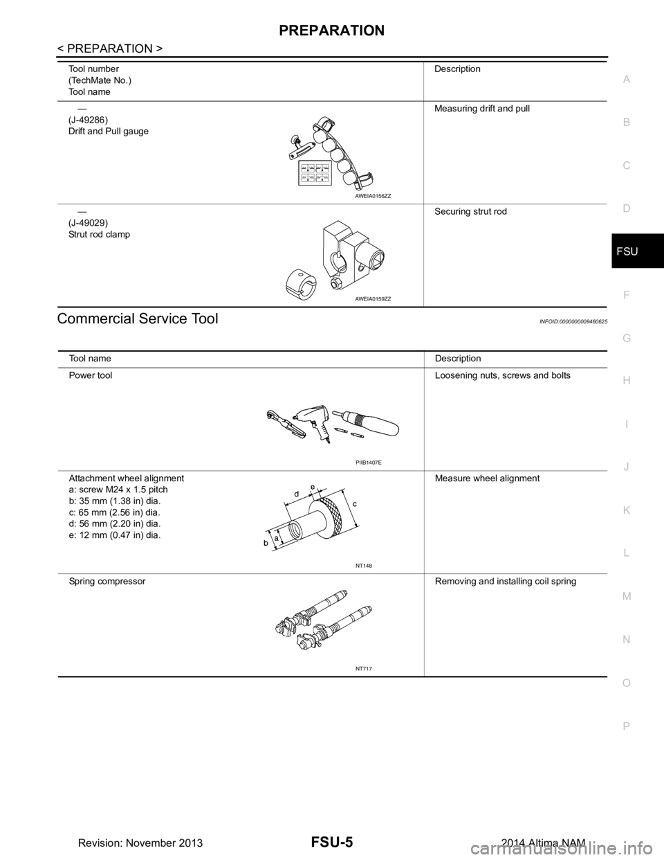
Commercial Service ToolINFOID:0000000009460625
—
(J-49286)
Drift and Pull gauge Measuring drift and pull
—
(J-49029)
Strut rod clamp Securing strut rod
Tool number
(TechMate No.)
Tool name Description
AWEIA0156ZZ
AWEIA0159ZZ
Tool name
Description
Power tool Loosening nuts, screws and bolts
Attachment wheel alignment
a: screw M24 x 1.5 pitch
b: 35 mm (1.38 in) dia.
c: 65 mm (2.56 in) dia.
d: 56 mm (2.20 in) dia.
e: 12 mm (0.47 in) dia. Measure wheel alignment
Spring compressor Removing and installing coil spring
PIIB1407E
NT148
NT717
Revision: November 20132014 Altima NAM
Page 2510 of 4801
FRONT COIL SPRING AND STRUTFSU-9
< REMOVAL AND INSTALLATION >
C
D
F
G H
I
J
K L
M A
B
FSU
N
O P
REMOVAL AND INSTALLATION
FRONT COIL SPRING AND STRUT
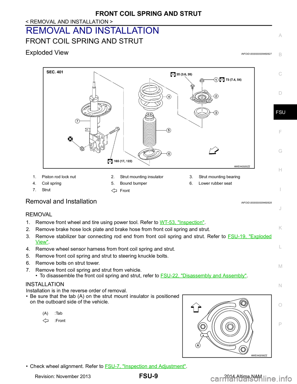
Exploded ViewINFOID:0000000009460627
Removal and InstallationINFOID:0000000009460628
REMOVAL
1. Remove front wheel and tire using power tool. Refer to WT-53, "Inspection".
2. Remove brake hose lock plate and brake hose from front coil spring and strut.
3. Remove stabilizer bar connecting rod end from front coil spring and strut. Refer to FSU-19, "Exploded
View".
4. Remove wheel sensor harness from front coil spring and strut.
5. Remove front coil spring and strut to steering knuckle bolts.
6. Remove bolts on strut tower.
7. Remove front coil spring and strut from vehicle. • To disassemble the front coil spring and strut, refer to FSU-22, "Disassembly and Assembly"
.
INSTALLATION
Installation is in the reverse order of removal.
• Be sure that the tab (A) on the strut mount insulator is positioned on the outboard side of the vehicle.
• Check wheel alignment. Refer to FSU-7, "Inspection and Adjustment"
.
1. Piston rod lock nut 2. Strut mounting insulator 3. Strut mounting bearing
4. Coil spring 5. Bound bumper 6. Lower rubber seat
7. Strut Front
AWEIA0325ZZ
(A) :Tab
:Front
AWEIA0259ZZ
Revision: November 20132014 Altima NAM
Page 2512 of 4801
TRANSVERSE LINKFSU-11
< REMOVAL AND INSTALLATION >
C
D
F
G H
I
J
K L
M A
B
FSU
N
O P
TRANSVERSE LINK
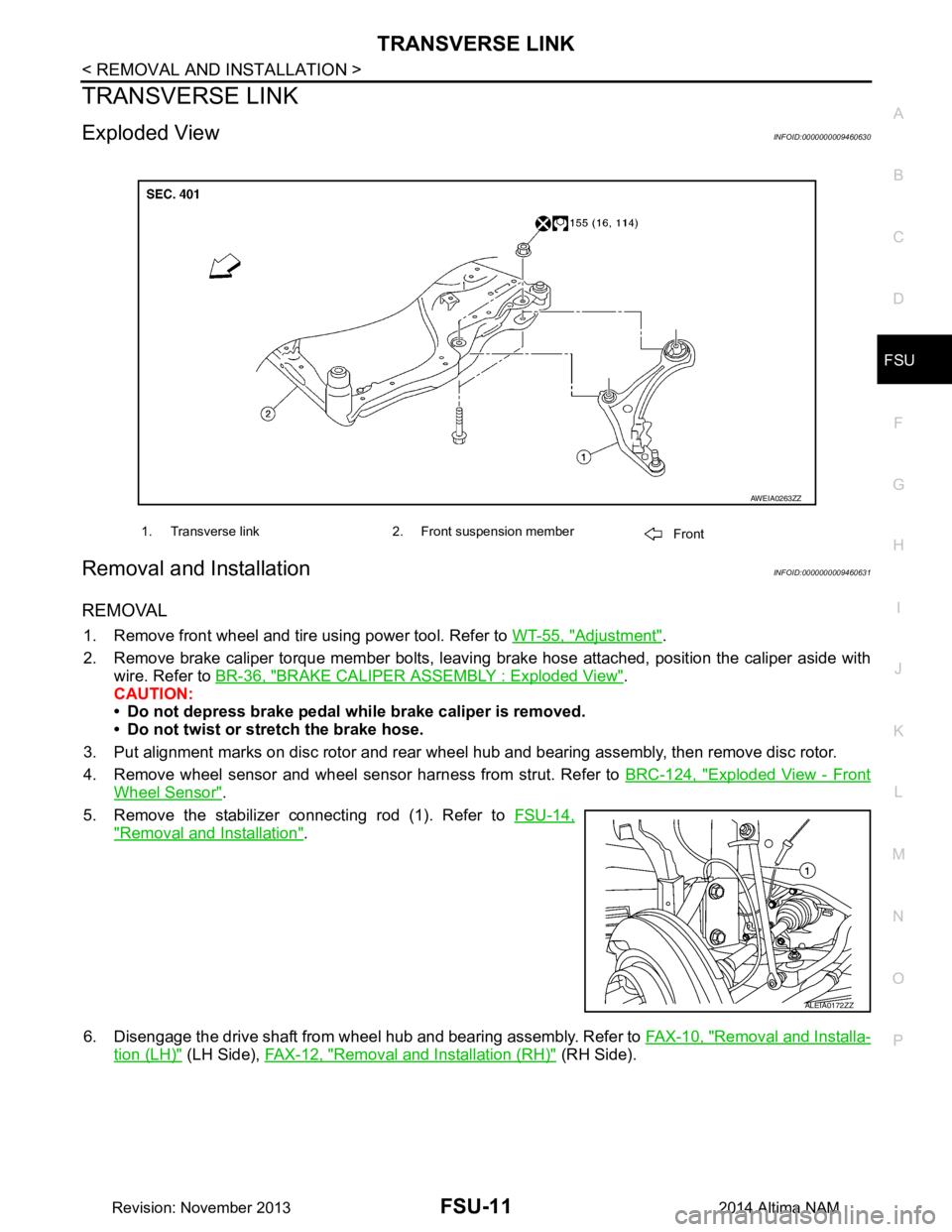
Exploded ViewINFOID:0000000009460630
Removal and InstallationINFOID:0000000009460631
REMOVAL
1. Remove front wheel and tire using power tool. Refer to WT-55, "Adjustment".
2. Remove brake caliper torque member bolts, leaving brake hose attached, position the caliper aside with
wire. Refer to BR-36, "BRAKE CALIPER ASSEMBLY : Exploded View"
.
CAUTION:
• Do not depress brake pedal while brake caliper is removed.
• Do not twist or stretch the brake hose.
3. Put alignment marks on disc rotor and rear wheel hub and bearing assembly, then remove disc rotor.
4. Remove wheel sensor and wheel sensor harness from strut. Refer to BRC-124, "Exploded View - Front
Wheel Sensor".
5. Remove the stabilizer connecting rod (1). Refer to FSU-14,
"Removal and Installation".
6. Disengage the drive shaft from wheel hub and bearing assembly. Refer to FAX-10, "Removal and Installa-
tion (LH)" (LH Side), FAX-12, "Removal and Installation (RH)" (RH Side).
1. Transverse link 2. Front suspension member
Front
AWEIA0263ZZ
ALEIA0172ZZ
Revision: November 20132014 Altima NAM