2014 NISSAN TEANA tow
[x] Cancel search: towPage 2028 of 4801
![NISSAN TEANA 2014 Service Manual
EM-30
< REMOVAL AND INSTALLATION >[QR25DE]
INTAKE MANIFOLD
INTAKE MANIFOLD
Exploded ViewINFOID:0000000009460480
Removal and InstallationINFOID:0000000009460481
REMOVAL
WARNING:
To avoid the danger o NISSAN TEANA 2014 Service Manual
EM-30
< REMOVAL AND INSTALLATION >[QR25DE]
INTAKE MANIFOLD
INTAKE MANIFOLD
Exploded ViewINFOID:0000000009460480
Removal and InstallationINFOID:0000000009460481
REMOVAL
WARNING:
To avoid the danger o](/manual-img/5/57390/w960_57390-2027.png)
EM-30
< REMOVAL AND INSTALLATION >[QR25DE]
INTAKE MANIFOLD
INTAKE MANIFOLD
Exploded ViewINFOID:0000000009460480
Removal and InstallationINFOID:0000000009460481
REMOVAL
WARNING:
To avoid the danger of being scalded, never drain the coolant when the engine is hot.
NOTE:
When removing components such as hoses, tubes/lines, etc. , cap or plug openings to prevent fluid from spill-
ing.
1. Disconnect battery negative terminal. Refer to PG-73, "Removal and Installation (Battery)"
.
2. Release the fuel pressure. Refer to EC-182, "Work Procedure"
.
3. Partially drain engine coolant. Refer to CO-12, "Changing Engine Coolant"
.
4. Remove the air cleaner and air duct. Refer to EM-29, "Removal and Installation"
.
5. Remove cowl top finisher. Refer to EXT-24, "Removal and Installation"
.
6. Remove strut tower bar. Refer to FSU-19, "Exploded View"
.
7. Disconnect the PCV hose from the intake manifold.
8. Disconnect the EVAP hose and EVAP canister purge volume control solenoid.
1. Electric throttle control actuator 2. Map sensor (California only) 3. Map hose (California only)
4. Clamp 5. Cap (except California) 6. Intake manifold gasket
7. Intake manifold 8. Electric throttle control actuator O-ringA. Refer to INSTALLATION
B. Refer to INSTALLATION C. Refer to INSTALLATION
AWBIA1768ZZ
Revision: November 20132014 Altima NAM
Page 2063 of 4801
![NISSAN TEANA 2014 Service Manual
TIMING CHAINEM-65
< REMOVAL AND INSTALLATION > [QR25DE]
C
D E
F
G H
I
J
K L
M A
EM
NP
O
15. Press stopper tab (A) in the direction shown to push the timing
chain slack guide (B) toward timing chain NISSAN TEANA 2014 Service Manual
TIMING CHAINEM-65
< REMOVAL AND INSTALLATION > [QR25DE]
C
D E
F
G H
I
J
K L
M A
EM
NP
O
15. Press stopper tab (A) in the direction shown to push the timing
chain slack guide (B) toward timing chain](/manual-img/5/57390/w960_57390-2062.png)
TIMING CHAINEM-65
< REMOVAL AND INSTALLATION > [QR25DE]
C
D E
F
G H
I
J
K L
M A
EM
NP
O
15. Press stopper tab (A) in the direction shown to push the timing
chain slack guide (B) toward timing chain tensioner (1) for the
balancer unit.
• The slack guide (B) is released by pressing the stopper tab
(A). As a result, the slack guide (B) can be moved.
16. Insert stopper pin (D) into tensioner body hole (C) to secure tim- ing chain slack guide (B).
NOTE:
Use a hard metal pin with a diameter of approximately 1.2 mm
(0.047 in) as a stopper pin.
17. Remove timing chain tensioner (1) for balancer unit.
18. Secure width across flats of the balancer unit LH side shaft using a suitable tool. Loosen the balancer unit sprocket bolt.
19. Remove balancer unit timing chain, balancer unit sprocket and crankshaft sprocket.
20. Loosen bolts in the reverse order shown, and remove balancer unit.
CAUTION:
• Do not disassemble balancer unit.
INSPECTION AFTER REMOVAL
Timing Chain
Check the timing chain for cracks or excessive wear. If a defect is
found, replace the timing chain.
Balancer Unit Bo lt Outer Diameter
PBIC5314E
: Engine front
AWBIA1380ZZ
PBIC0282E
Revision: November 20132014 Altima NAM
Page 2144 of 4801
![NISSAN TEANA 2014 Service Manual
EM-146
< REMOVAL AND INSTALLATION >[VQ35DE]
INTAKE MANIFOLD COLLECTOR
INTAKE MANIFOLD COLLECTOR
Exploded ViewINFOID:0000000009460541
CAUTION:
Do not remove power valves.
Removal and InstallationINFO NISSAN TEANA 2014 Service Manual
EM-146
< REMOVAL AND INSTALLATION >[VQ35DE]
INTAKE MANIFOLD COLLECTOR
INTAKE MANIFOLD COLLECTOR
Exploded ViewINFOID:0000000009460541
CAUTION:
Do not remove power valves.
Removal and InstallationINFO](/manual-img/5/57390/w960_57390-2143.png)
EM-146
< REMOVAL AND INSTALLATION >[VQ35DE]
INTAKE MANIFOLD COLLECTOR
INTAKE MANIFOLD COLLECTOR
Exploded ViewINFOID:0000000009460541
CAUTION:
Do not remove power valves.
Removal and InstallationINFOID:0000000009460542
REMOVAL
WARNING:
To avoid the danger of being scalded, do no t drain the coolant when the engine is hot.
1. Remove the cowl top. Refer to EXT-24, "Removal and Installation"
.
2. Remove the strut tower bar. Refer to FSU-19, "Exploded View"
.
3. Remove the engine room cover. Refer to EM-143, "Removal and Installation"
.
4. Remove front air duct and air duct hose and resonator assembly. Refer to EM-144, "Removal and Installa-
tion".
5. Partially drain the engine coolant. Refer to CO-36, "Changing Engine Coolant"
.
NOTE:
1. Intake manifold collector 2. Intake manifold collector gasket 3. Electric throttle control actuator gasket
4. Electric throttle control actuator A. Refer to INSTALLATION B. Refer to INSTALLATION
AWBIA1336ZZ
Revision: November 20132014 Altima NAM
Page 2161 of 4801
![NISSAN TEANA 2014 Service Manual
FUEL INJECTOR AND FUEL TUBEEM-163
< REMOVAL AND INSTALLATION > [VQ35DE]
C
D E
F
G H
I
J
K L
M A
EM
NP
O
FUEL INJECTOR AND FUEL TUBE
Exploded ViewINFOID:0000000009460554
CAUTION:
• Apply new engin NISSAN TEANA 2014 Service Manual
FUEL INJECTOR AND FUEL TUBEEM-163
< REMOVAL AND INSTALLATION > [VQ35DE]
C
D E
F
G H
I
J
K L
M A
EM
NP
O
FUEL INJECTOR AND FUEL TUBE
Exploded ViewINFOID:0000000009460554
CAUTION:
• Apply new engin](/manual-img/5/57390/w960_57390-2160.png)
FUEL INJECTOR AND FUEL TUBEEM-163
< REMOVAL AND INSTALLATION > [VQ35DE]
C
D E
F
G H
I
J
K L
M A
EM
NP
O
FUEL INJECTOR AND FUEL TUBE
Exploded ViewINFOID:0000000009460554
CAUTION:
• Apply new engine oil when installi ng the parts as specified to do so.
• Do not remove or disassemble part s unless instructed as shown.
Removal and InstallationINFOID:0000000009460555
REMOVAL
WARNING:
• Put a “CAUTION: FLAMMABLE” sign in the workshop.
• Be sure to work in a well ventila ted area and furnish workshop with a CO
2 fire extinguisher.
• Do not smoke while servicing fuel system. Keep open flames and sparks away from the work area.
• To avoid the danger of being scalded, do no t drain engine coolant when engine is hot.
1. Remove engine room cover. Refer to EM-143, "Removal and Installation"
.
2. Release the fuel pressure. Refer to EC-687, "Work Procedure"
.
3. Disconnect the battery negative terminal. Refer to PG-73, "Removal and Installation (Battery)"
.
4. Remove front wiper arm and cowl top extension. Refer to EXT-24, "Removal and Installation"
.
5. Remove strut tower bar. Refer to FSU-19, "Exploded View"
.
AWBIA1351ZZ
1. Fuel feed hose 2. Quick connector cap 3. Fuel tube
4. O-ring 5. Fuel damper 6. Fuel damper cap
7. Clip 8. O-ring (black) 9. Fuel injector
10. O-ring (green) A. Refer to INSTALLATION
Revision: November 20132014 Altima NAM
Page 2275 of 4801

SYSTEMEXL-9
< SYSTEM DESCRIPTION >
C
D E
F
G H
I
J
K
M A
B
EXL
N
O P
SYSTEM
HEADLAMP SYSTEM
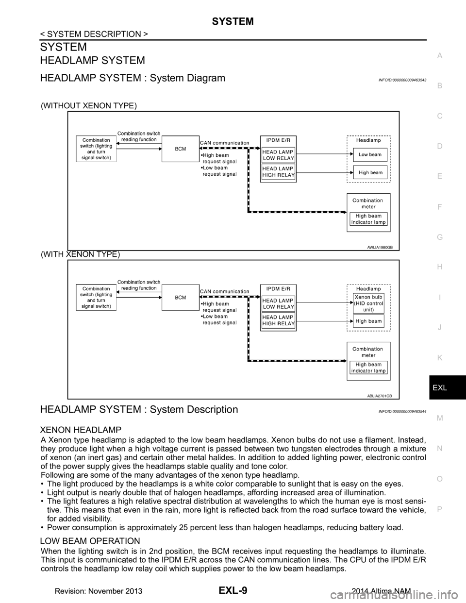
HEADLAMP SYSTEM : System DiagramINFOID:0000000009463543
(WITHOUT XENON TYPE)
(WITH XENON TYPE)
HEADLAMP SYSTEM : System DescriptionINFOID:0000000009463544
XENON HEADLAMP
A Xenon type headlamp is adapted to the low beam headlamps. Xenon bulbs do not use a filament. Instead,
they produce light when a high voltage current is pa ssed between two tungsten electrodes through a mixture
of xenon (an inert gas) and certain other metal halides. In addition to added lighting power, electronic control
of the power supply gives the headlamps stable quality and tone color.
Following are some of the many advantages of the xenon type headlamp.
• The light produced by the headlamps is a white color comparable to sunlight that is easy on the eyes.
• Light output is nearly double that of halogen headl amps, affording increased area of illumination.
• The light features a high relative spectral distributi on at wavelengths to which the human eye is most sensi-
tive. This means that even in the rain, more light is reflected back from the road surface toward the vehicle,
for added visibility.
• Power consumption is approximately 25 percent less than halogen headlamps, reducing battery load.
LOW BEAM OPERATION
When the lighting switch is in 2nd position, the BCM receives input requesting the headlamps to illuminate.
This input is communicated to the IPDM E/R across the CAN communication lines. The CPU of the IPDM E/R
controls the headlamp low relay coil which supplies power to the low beam headlamps.
AWLIA1980GB
ABLIA2701GB
Revision: November 20132014 Altima NAMRevision: November 20132014 Altima NAM
Page 2388 of 4801

EXL-122
< PERIODIC MAINTENANCE >
HEADLAMP
PERIODIC MAINTENANCE
HEADLAMP
Aiming AdjustmentINFOID:0000000009463617
PREPARATION BEFORE ADJUSTING
Before performing aiming adjustment, check the following:
• Ensure all tires are inflated to correct pressure.
• Place vehicle and screen on level surface.
• Ensure there is no load in vehicle other than the driver (or equivalent weight placed in driver's position).
• Coolant and engine oil filled to correct level, and fuel tank full.
• Remove cargo and/or luggage to maintain an unloaded vehicle condition.
• Confirm spare tire, jack and tools are properly stowed.
• Carefully wipe off any dirt from headlamp lens. CAUTION:
Do not use organic solvent (thinner, gasoline etc.)
• Place a driver or equivalent weight of 68.5 kg (150 lb) on the driver seat.
• By hand, bounce the front and rear of the vehicle to settle the suspension and eliminate any static load.
• Place the front tires in the straight ahead position.
• Aim each headlamp individually and ensure other headlamp beam pattern is blocked from screen.
NOTE:
• For headlamp aiming details, refer to regulations in your area.
• By regulation, no means for horizontal aim adjustment is provided from the factory; only vertical aim is
adjustable.
• Use adjusting screw to perform aiming adjustment.
• Perform headlamp aiming if:
- The vehicle front body has been repaired.
- The front combination lamp has been removed or replaced.
- Any outfitting has been installed.
- The vehicle’s standard load condition has been substantially increased.
Aiming Adjustment procedure
1. Position the screen.
NOTE:
• Stop the vehicle facing the screen.
• Place the screen on a plain road vertically.
2. Face the screen with the vehicle. Maintain 10 m (33 ft) between the headlamp bulb center and the screen.
3. Start the engine. Turn the headlamp (LO) ON.
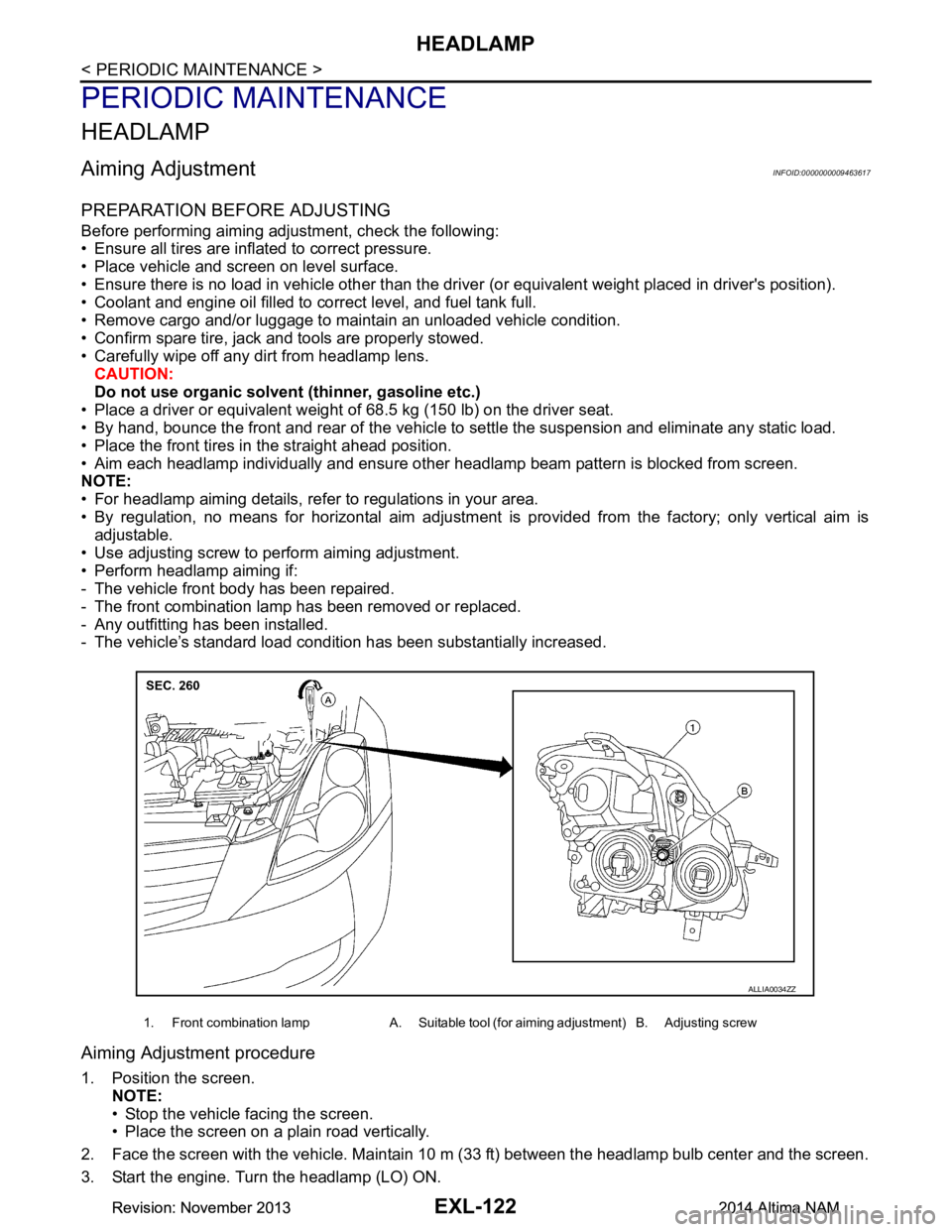
1. Front combination lamp A. Suitable tool (for aiming adjustment) B. Adjusting screw
ALLIA0034ZZ
Revision: November 20132014 Altima NAMRevision: November 20132014 Altima NAM
Page 2390 of 4801

EXL-124
< PERIODIC MAINTENANCE >
FRONT FOG LAMP
FRONT FOG LAMP
Aiming AdjustmentINFOID:0000000009463618
PREPARATION BEFORE ADJUSTING
The fog lamp is a semi-sealed beam type which uses a replaceable halogen bulb. Before performing aiming
adjustment procedure, check the following:
• Ensure all tires are inflated to correct pressure.
• Place vehicle and screen on level surface.
• Ensure there is no load in vehicle other than the driver (or equivalent weight placed in driver's position).
• Coolant and engine oil filled to correct level, and fuel tank full.
• Remove cargo and/or luggage to maintain an unloaded vehicle condition.
• Confirm spare tire, jack and tools are properly stowed.
• Carefully wipe off any dirt from headlamp lens. CAUTION:
Do not use organic solvent (thinner, gasoline etc.)
• Place a driver or equivalent weight of 68.5 kg (150 lb) on the driver seat.
• By hand, bounce the front and rear of the vehicle to settle the suspension and eliminate any static load.
• Place the front tires in the straight ahead position.
• Aim each headlamp individually and ensure other headlamp beam pattern is blocked from screen.
NOTE:
• For headlamp aiming details, refer to regulations in your area.
• By regulation, no means for horizontal aim adjustment is provided from the factory; only vertical aim is
adjustable.
• Use adjusting screw to perform aiming adjustment.
• Perform headlamp aiming if:
- The vehicle front body has been repaired.
- The front combination lamp has been removed or replaced.
- Any outfitting has been installed.
- The vehicle’s standard load condition has been substantially increased.
Aiming Adjustment Procedure
1. Place the screen. NOTE:
• Stop the vehicle facing the wall.
• Place the board on a plain road vertically.
2. Face the vehicle with the screen. Maintain 7.62 m (25.0 ft) between the front fog lamp center and the
screen.
3. Start the engine. Turn the front fog lamp ON. NOTE:
Shut off the headlamp light with the board to prevent from illuminating the adjustment screen.
CAUTION:
Do not cover the lens surface with a tape etc. The lens is made of resin.
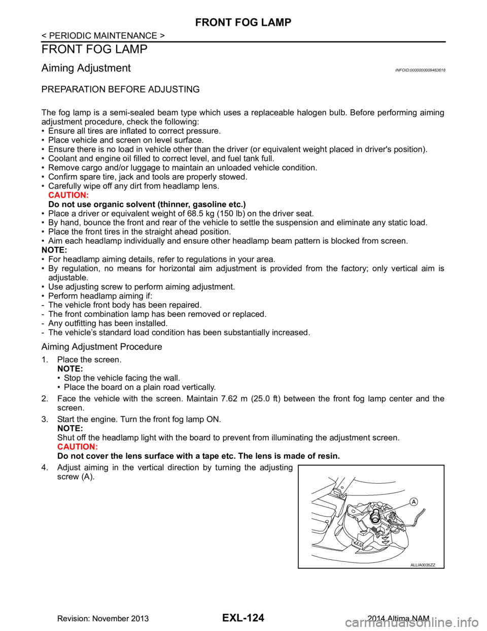
4. Adjust aiming in the vertical direction by turning the adjusting screw (A).
ALLIA0035ZZ
Revision: November 20132014 Altima NAMRevision: November 20132014 Altima NAM
Page 2431 of 4801

FRONT BUMPEREXT-17
< REMOVAL AND INSTALLATION >
C
D E
F
G H
I
J
L
M A
B
EXT
N
O P
Removal and InstallationINFOID:0000000009460995
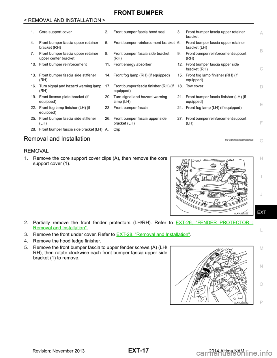
REMOVAL
1. Remove the core support cover clips (A), then remove the core support cover (1).
2. Partially remove the front fender protectors (LH/RH). Refer to EXT-26, "FENDER PROTECTOR :
Removal and Installation".
3. Remove the front under cover. Refer to EXT-28, "Removal and Installation"
.
4. Remove the hood ledge finisher.
5. Remove the front bumper fascia to upper fender screws (A) (LH/ RH), then rotate clockwise each front bumper fascia upper side
bracket (1) to remove.
1. Core support cover 2. Front bumper fascia hood seal 3. Front bumper fascia upper retainer
bracket
4. Front bumper fascia upper retainer bracket (RH) 5. Front bumper reinforcement bracket 6. Front bumper fascia upper retainer
bracket (LH)
7. Front bumper fascia upper retainer upper center bracket 8. Front bumper fascia side bracket
(RH) 9. Front bumper reinforcement support
(RH)
10. Front bumper reinforcement 11. Front energy absorber 12. Front bumper fascia upper side bracket (RH)
13. Front bumper fascia side stiffener (RH) 14. Front fog lamp (RH) (if equipped) 15. Front fog lamp finisher (RH) (if
equipped)
16. Turn signal and hazard warning lamp (RH) 17. Front bumper fascia finisher (RH) (if
equipped) 18. Tow cover
19. Front license plate bracket (if equipped) 20. Turn signal and hazard warning
lamp (LH) 21. Front bumper fascia finisher (LH) (if
equipped)
22. Front fog lamp finisher (LH) (if equipped) 23. Front bumper fascia 24. Front fog lamp (LH) (if equipped)
25. Front bumper fascia side stiffener (LH) 26. Front bumper fascia upper side
bracket (LH) 27. Front bumper reinforcement support
(LH)
28. Front bumper fascia side bracket (LH) A. Clip
ALKIA2602ZZ
ALKIA2603ZZ
Revision: November 20132014 Altima NAM