2014 NISSAN TEANA tow
[x] Cancel search: towPage 2564 of 4801
GI-36
< PRECAUTION >
TOW TRUCK TOWING
TOW TRUCK TOWING
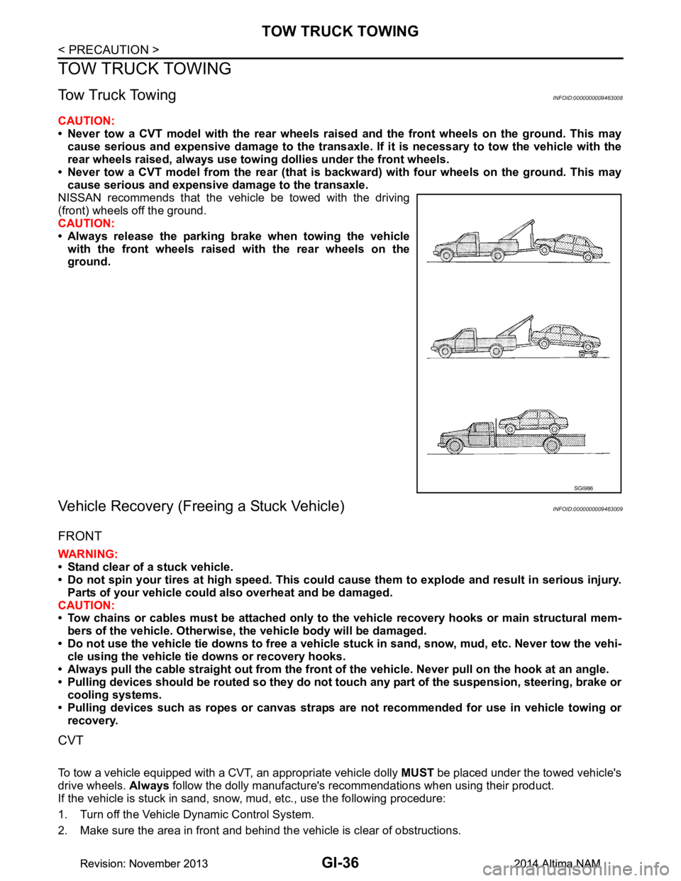
Tow Truck TowingINFOID:0000000009463008
CAUTION:
• Never tow a CVT model with the rear wheels raised and the front wheels on the ground. This may
cause serious and expensive damage to the transaxle. If it is necessary to tow the vehicle with the
rear wheels raised, always use towi ng dollies under the front wheels.
• Never tow a CVT model from the rear (that is backw ard) with four wheels on the ground. This may
cause serious and expensive damage to the transaxle.
NISSAN recommends that the vehicle be towed with the driving
(front) wheels off the ground.
CAUTION:
• Always release the parking brake when towing the vehicle with the front wheels raised with the rear wheels on the
ground.
Vehicle Recovery (Freeing a Stuck Vehicle)INFOID:0000000009463009
FRONT
WARNING:
• Stand clear of a stuck vehicle.
• Do not spin your tires at high speed. This could cause them to explode and result in serious injury.
Parts of your vehicle could also overheat and be damaged.
CAUTION:
• Tow chains or cables must be attached only to the vehicle recovery hooks or main structural mem-
bers of the vehicle. Otherwise, the vehicle body will be damaged.
• Do not use the vehicle tie downs to free a vehicle stuck in sand, snow, mud, etc. Never tow the vehi-
cle using the vehicle tie downs or recovery hooks.
• Always pull the cable straight out from the front of the vehicle. Never pull on the hook at an angle.
• Pulling devices should be routed so they do not touch any part of the suspension, steering, brake or
cooling systems.
• Pulling devices such as ropes or canvas straps ar e not recommended for use in vehicle towing or
recovery.
CVT
To tow a vehicle equipped with a CVT, an appropriate vehicle dolly MUST be placed under the towed vehicle's
drive wheels. Always follow the dolly manufacture's recommendations when using their product.
If the vehicle is stuck in sand, snow , mud, etc., use the following procedure:
1. Turn off the Vehicle Dynamic Control System.
2. Make sure the area in front and behind the vehicle is clear of obstructions.
SGI986
Revision: November 20132014 Altima NAMRevision: November 20132014 Altima NAM
Page 2565 of 4801

TOW TRUCK TOWINGGI-37
< PRECAUTION >
C
D E
F
G H
I
J
K L
M B
GI
N
O P
3. Turn the steering wheel right and left to clear an area around the front tires.
4. Slowly rock the vehicle forward and backward. Shift back and forth between R (reverse) and D (drive).
Apply the accelerator as little as possible to maintain the rocking motion.
Release the accelerator pedal before shifting between R and D.
Do not spin the tires above 35 m.p.h. (55 km/h).
5. If the vehicle can not be freed after a few tries, cont act a professional towing service to remove the vehi-
cle.
Revision: November 20132014 Altima NAMRevision: November 20132014 Altima NAM
Page 2594 of 4801
GW-14
< REMOVAL AND INSTALLATION >
FRONT DOOR GLASS
FRONT DOOR GLASS
Removal and InstallationINFOID:0000000009463662
WARNING:
• Before servicing, turn ignition sw itch OFF, disconnect both battery terminals and wait at least three
minutes.
• Do not use air tools or el ectric tools for servicing.
REMOVAL
NOTE:
LH side shown; RH side similar
1. Disconnect the battery positive and negative terminal. Refer to PG-73, "Removal and Installation (Bat-
tery)".
2. Remove the front door finisher. Refer to INT-15, "Removal and Installation"
.
3. Remove the vapor barrier. CAUTION:
Use care to not damage or tear vapor barrier during removal.
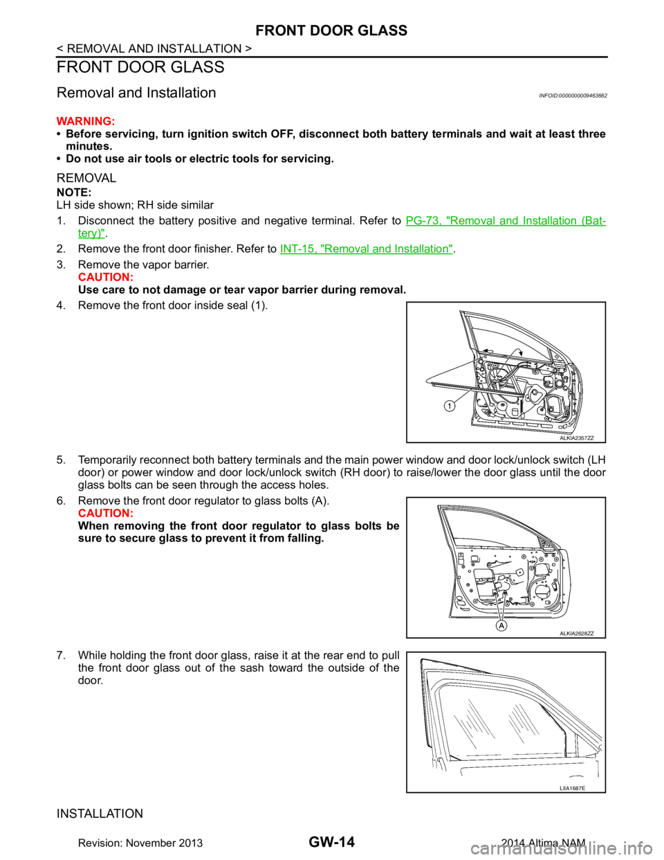
4. Remove the front door inside seal (1).
5. Temporarily reconnect both battery terminals and the main power window and door lock/unlock switch (LH door) or power window and door lock/unlock switch ( RH door) to raise/lower the door glass until the door
glass bolts can be seen through the access holes.
6. Remove the front door regul ator to glass bolts (A).
CAUTION:
When removing the front door regulator to glass bolts be
sure to secure glass to prevent it from falling.
7. While holding the front door glass, raise it at the rear end to pull the front door glass out of the sash toward the outside of the
door.
INSTALLATION
ALKIA2357ZZ
ALKIA2628ZZ
LIIA1687E
Revision: November 20132014 Altima NAM
Page 2641 of 4801
COOLER PIPE AND HOSEHA-35
< REMOVAL AND INSTALLATION >
C
D E
F
G H
J
K L
M A
B
HA
N
O P
Installation is in the reverse order of removal.
CAUTION:
• Do not reuse O-rings.
• Apply A/C oil to the new O-rings.
• After charging refrigerant, check for leaks. Refer to HA-21, "Leak Test"
.
HIGH-PRESSURE FLEXIBLE HOSE
HIGH-PRESSURE FLEXIBLE HOSE : Removal and InstallationINFOID:0000000009463941
REMOVAL
1. Discharge the refrigerant. Refer to HA-23, "Recycle Refrigerant".
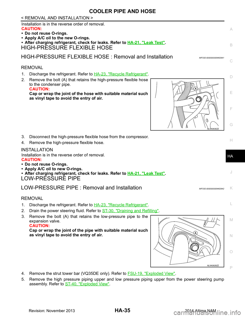
2. Remove the bolt (A) that retains the high-pressure flexible hose to the condenser pipe.
CAUTION:
Cap or wrap the joint of the ho se with suitable material such
as vinyl tape to avoid the entry of air.
3. Disconnect the high-pressure flex ible hose from the compressor.
4. Remove the high-pressure flexible hose.
INSTALLATION
Installation is in the reverse order of removal.
CAUTION:
• Do not reuse O-rings.
• Apply A/C oil to new O-rings.
• After charging refrigerant, check for leaks. Refer to HA-21, "Leak Test"
.
LOW-PRESSURE PIPE
LOW-PRESSURE PIPE : Re moval and InstallationINFOID:0000000009463942
REMOVAL
1. Discharge the refrigerant. Refer to HA-23, "Recycle Refrigerant".
2. Drain the power steering fluid. Refer to ST-30, "Draining and Refilling"
.
3. Remove the bolt (A) that retains the low-pressure pipe to the expansion valve.
CAUTION:
Cap or wrap the joint of the pi pe with suitable material such
as vinyl tape to avoid the entry of air.
4. Remove the strut tower bar (VQ35DE only). Refer to FSU-19, "Exploded View"
.
5. Remove the high pressure piping upper and low pressure piping upper from the power steering pump assembly. Refer to ST-40, "Exploded View"
.
ALIIA0630ZZ
ALIIA0629ZZ
Revision: November 20132014 Altima NAM
Page 2642 of 4801
HA-36
< REMOVAL AND INSTALLATION >
COOLER PIPE AND HOSE
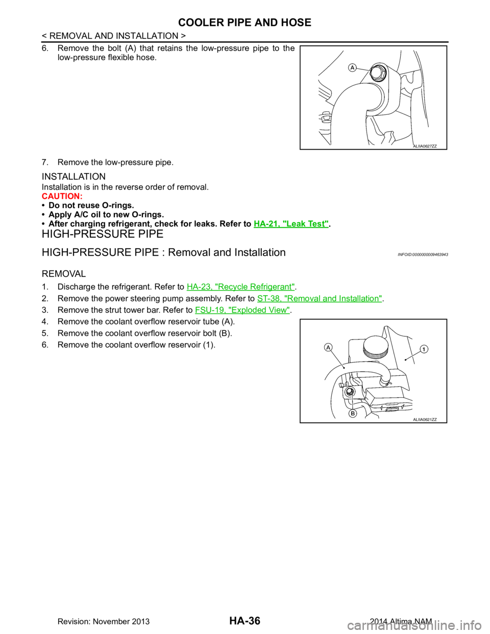
6. Remove the bolt (A) that retains the low-pressure pipe to thelow-pressure flexible hose.
7. Remove the low-pressure pipe.
INSTALLATION
Installation is in the reverse order of removal.
CAUTION:
• Do not reuse O-rings.
• Apply A/C oil to new O-rings.
• After charging refrigerant, check for leaks. Refer to HA-21, "Leak Test"
.
HIGH-PRESSURE PIPE
HIGH-PRESSURE PIPE : Removal and InstallationINFOID:0000000009463943
REMOVAL
1. Discharge the refrigerant. Refer to HA-23, "Recycle Refrigerant".
2. Remove the power steering pump assembly. Refer to ST-38, "Removal and Installation"
.
3. Remove the strut tower bar. Refer to FSU-19, "Exploded View"
.
4. Remove the coolant overflow reservoir tube (A).
5. Remove the coolant overflow reservoir bolt (B).
6. Remove the coolant overflow reservoir (1).
ALIIA0627ZZ
ALIIA0621ZZ
Revision: November 20132014 Altima NAM
Page 2647 of 4801
HEATING AND COOLING UNIT ASSEMBLYHA-41
< REMOVAL AND INSTALLATION >
C
D E
F
G H
J
K L
M A
B
HA
N
O P
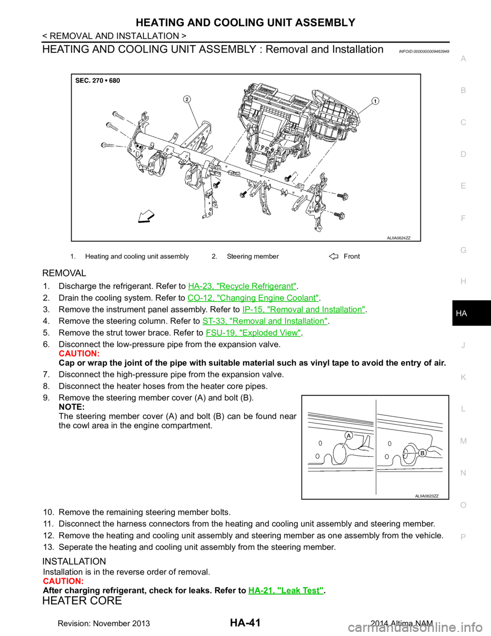
HEATING AND COOLING UNIT ASSEMB LY : Removal and InstallationINFOID:0000000009463949
REMOVAL
1. Discharge the refrigerant. Refer to HA-23, "Recycle Refrigerant".
2. Drain the cooling system. Refer to CO-12, "Changing Engine Coolant"
.
3. Remove the instrument panel assembly. Refer to IP-15, "Removal and Installation"
.
4. Remove the steering column. Refer to ST-33, "Removal and Installation"
.
5. Remove the strut tower brace. Refer to FSU-19, "Exploded View"
.
6. Disconnect the low-pressure pipe from the expansion valve. CAUTION:
Cap or wrap the joint of the pipe with suitable ma terial such as vinyl tape to avoid the entry of air.
7. Disconnect the high-pressure pi pe from the expansion valve.
8. Disconnect the heater hoses from the heater core pipes.
9. Remove the steering member cover (A) and bolt (B). NOTE:
The steering member cover (A) and bolt (B) can be found near
the cowl area in the engine compartment.
10. Remove the remaining steering member bolts.
11. Disconnect the harness connectors from the heati ng and cooling unit assembly and steering member.
12. Remove the heating and cooling unit assembly and steering member as one assembly from the vehicle.
13. Seperate the heating and cooling unit assembly from the steering member.
INSTALLATION
Installation is in the reverse order of removal.
CAUTION:
After charging refrigerant, check for leaks. Refer to HA-21, "Leak Test"
.
HEATER CORE
1. Heating and cooling unit assembly 2. Steering member Front
ALIIA0624ZZ
ALIIA0623ZZ
Revision: November 20132014 Altima NAM
Page 2648 of 4801
HA-42
< REMOVAL AND INSTALLATION >
HEATING AND COOLING UNIT ASSEMBLY
HEATER CORE : Removal and Installation
INFOID:0000000009463950
REMOVAL
1. Remove the heating and cooling unit assembly. Refer to HA-41, "HEATING AND COOLING UNIT
ASSEMBLY : Removal and Installation".
2. Remove the heater core pipes cover. Refer to HA-40, "Exploded View"
.
3. Disconnect the harness connector from the blower motor.
4. Remove the heater core.
INSTALLATION
Installation is in the reverse order of removal.
EVAPORATOR
EVAPORATOR : Removal and InstallationINFOID:0000000009463951
REMOVAL
1. Remove the heater core. Refer to HA-42, "HEATER CORE : Removal and Installation".
2. Remove the upper floor connecting duct (RH). Refer to HA-40, "Exploded View"
.
3. Remove the air mix door motor (driver). Refer to HAC-109, "AIR MIX DOOR MOTOR : Removal and
Installation - Air Mix Door Motor (RH)".
4. Remove the air mix door motor (passenger) (if equipped). Refer to HAC-109, "AIR MIX DOOR MOTOR :
Removal and Installation - Air Mix Door Motor (LH)"
5. Disconnect the harness connector from the intake sensor.
6. Remove the evaporator and expansion valve assembly.
INSTALLATION
Installation is in the reverse order of removal.
NOTE:
The evaporator can only be ordered as an assembly with the expansion valve.
EXPANSION VALVE
EXPANSION VALVE : Removal and Installation for Expansion ValveINFOID:0000000009463952
REMOVAL
1. Discharge the refrigerant. Refer to HA-23, "Recycle Refrigerant".
2. Remove the strut tower brace. Refer to FSU-19, "Exploded View"
.
3. Disconnect the low-pressure pipe from the expansion valve.
4. Disconnect the high-pressure pipe from the expansion valve.
5. Remove the expansion valve bolts.
6. Remove the expansion valve.
INSTALLATION
Installation is in the reverse order of removal.
CAUTION:
After charging refrigerant, check for leaks. Refer to HA-21, "Leak Test"
.
Revision: November 20132014 Altima NAM
Page 3193 of 4801
PERIODIC MAINTENANCEMA-9
< PERIODIC MAINTENANCE >
C
D E
F
G H
I
J
K L
M B
MA
N
O A
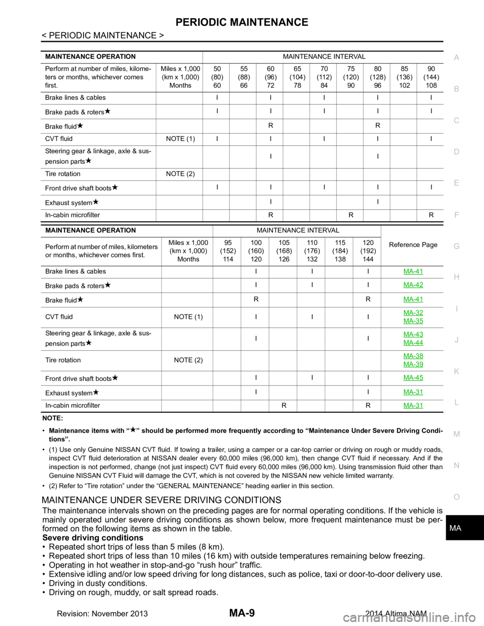
NOTE:
• Maintenance items with “ ” shoul d be performed more frequently according to “Maintenance Under Severe Driving Condi-
tions”.
• (1) Use only Genuine NISSAN CVT fluid. If towing a trailer, using a camper or a car-top carrier or driving on rough or muddy r oads,
inspect CVT fluid deteriorat ion at NISSAN dealer every 60,000 miles (96,000 km), then change CVT fluid if necessary. And if the
inspection is not performed, change (not just inspect) CVT fluid every 60,000 miles (96,000 km). Using transmission fluid other than
Genuine NISSAN CVT Fluid will damage the CVT, which is not covered by the NISSAN new vehicle limited warranty.
• (2) Refer to “Tire rotation” under the “GENERAL MAINTENANCE” heading earlier in this section.
MAINTENANCE UNDER SEVERE DRIVING CONDITIONS
The maintenance intervals shown on the preceding pages are for normal operating conditions. If the vehicle is
mainly operated under severe driving conditions as shown below, more frequent maintenance must be per-
formed on the following items as shown in the table.
Severe driving conditions
• Repeated short trips of less than 5 miles (8 km).
• Repeated short trips of less than 10 miles (16 km) wi th outside temperatures remaining below freezing.
• Operating in hot weather in stop-and-go “rush hour” traffic.
• Extensive idling and/or low speed driving for long distances , such as police, taxi or door-to-door delivery use.
• Driving in dusty conditions.
• Driving on rough, muddy, or salt spread roads.
MAINTENANCE OPERATION MAINTENANCE INTERVAL
Perform at number of miles, kilome-
ters or months, whichever comes
first. Miles x 1,000
(km x 1,000) Months 50
(80) 60 55
(88) 66 60
(96) 72 65
(104) 78 70
(112) 84 75
(120) 90 80
(128) 96 85
(136) 102 90
(144) 108
Brake lines & cables IIIII
Brake pads & roters IIIII
Brake fluid RR
CVT fluid NOTE (1)IIIII
Steering gear & linkage, axle & sus-
pension parts II
Tire rotation NOTE (2)
Front drive shaft boots IIIII
Exhaust system II
In-cabin microfilter R R R
MAINTENANCE OPERATION MAINTENANCE INTERVAL
Reference Page
Perform at number of miles, kilometers
or months, whichever comes first. Miles x 1,000
(km x 1,000)
Months 95
(152)
11 4 100
(160)
120 105
(168)
126 11 0
(176)
132 11 5
(184)
138 120
(192)
144
Brake lines & cables I I I MA-41
Brake pads & rotersIII
MA-42
Brake fluid RR
MA-41
CVT fluid NOTE (1)III MA-32MA-35
Steering gear & linkage, axle & sus-
pension parts II
MA-43
MA-44
Tire rotation NOTE (2) MA-38MA-39
Front drive shaft boots
III
MA-45
Exhaust system II
MA-31
In-cabin microfilter R R MA-31
Revision: November 20132014 Altima NAM