2014 NISSAN TEANA recommended oil
[x] Cancel search: recommended oilPage 2178 of 4801
![NISSAN TEANA 2014 Service Manual
EM-180
< REMOVAL AND INSTALLATION >[VQ35DE]
FRONT TIMING CHAIN CASE
8. Install upper oil pan bolts (1) and (2) as shown. Refer to
EM-157,
"Removal and Installation (Upper Oil Pan)".
9. Install lower NISSAN TEANA 2014 Service Manual
EM-180
< REMOVAL AND INSTALLATION >[VQ35DE]
FRONT TIMING CHAIN CASE
8. Install upper oil pan bolts (1) and (2) as shown. Refer to
EM-157,
"Removal and Installation (Upper Oil Pan)".
9. Install lower](/manual-img/5/57390/w960_57390-2177.png)
EM-180
< REMOVAL AND INSTALLATION >[VQ35DE]
FRONT TIMING CHAIN CASE
8. Install upper oil pan bolts (1) and (2) as shown. Refer to
EM-157,
"Removal and Installation (Upper Oil Pan)".
9. Install lower oil pan. Refer to EM-156, "Removal and Installation (Lower Oil Pan)"
.
10. Install intake valve timing control solenoid valve covers as follows:
a. Install new O-rings in shaft grooves. CAUTION:
Do not reuse O-rings.
b. Being careful not to move O-rings from the installation grooves, align dowel pins on front timing chain case with the holes to install valve timing control covers.
c. Tighten intake valve timing control solenoid valve cover bolts in numerical order as shown.
11. Apply liquid gasket and install the water pump cover, if removed. • Use Genuine Silicone RTV Sealant or equivalent. Refer to GI-21, "Recommended Chemical Products
and Sealants".
12. Install crankshaft pulley and tighten the bolt in two steps. • Lubricate thread and seat surface of the bolt with new engineoil.
• Apply a paint mark for the second step of angle tightening.
13. Remove Tool and install the access plate. CAUTION:
Do not damage the ring gear teeth, or the signa l plate teeth behind the ring gear, when removing
the Tool.
14. Rotate crankshaft pulley in normal direction (clock wise when viewed from front) to confirm it turns
smoothly.
15. Installation of the remaining components is in the reverse order of removal.
INSPECTION AFTER INSTALLATION
WBIA0259E
(A) : Bank 1 (RH)
(B) : Bank 2 (LH)
(C) : Dowel pin hole
Intake valve timing control
solenoid valve cover bolts : 11.3 N·m (1.2 kg-m, 8 ft-lb)
JPBIA1639ZZ
Step 1 : 44 N·m (4.5 kg-m, 32 ft-lb)
Step 2 : 84 ° - 90 ° degrees clockwise
Tool Number : KV10112100 (BT-8653-A)
SEM531G
Tool number : — (J-50288)
Revision: November 20132014 Altima NAM
Page 2204 of 4801
![NISSAN TEANA 2014 Service Manual
EM-206
< REMOVAL AND INSTALLATION >[VQ35DE]
OIL SEAL
d. Apply sealant to rear oil seal retainer as shown.
Use Genuine Silicone RTV Seal ant, or equivalent. Refer to
GI-21, "Recommended Chemi cal Prod NISSAN TEANA 2014 Service Manual
EM-206
< REMOVAL AND INSTALLATION >[VQ35DE]
OIL SEAL
d. Apply sealant to rear oil seal retainer as shown.
Use Genuine Silicone RTV Seal ant, or equivalent. Refer to
GI-21, "Recommended Chemi cal Prod](/manual-img/5/57390/w960_57390-2203.png)
EM-206
< REMOVAL AND INSTALLATION >[VQ35DE]
OIL SEAL
d. Apply sealant to rear oil seal retainer as shown.
Use Genuine Silicone RTV Seal ant, or equivalent. Refer to
GI-21, "Recommended Chemi cal Products and Sealants"
.
• Assembly should be completed within 5 minutes after coating.
e. Lubricate the sealing surface of the new rear main seal with new engine oil.
f. Slide the new rear main seal (1) over the Tool (A) and onto the crankshaft.
g. Loosen the wing nut and push the threaded rod into the handle to remove the Tool (A).
h. Tighten the rear oil seal retainer bolts to specification.
3. Installation of the remaining components is in the reverse order of removal. CAUTION:
• When replacing an engine or transmission you must make sure the dowels are installed cor-
rectly during re-assembly.
• Improper alignment caused by missing dowels may cause vibration, oil leaks or breakage of
drivetrain components.
AWBIA0028ZZ
ALBIA0653ZZ
Revision: November 20132014 Altima NAM
Page 2508 of 4801
FRONT SUSPENSION ASSEMBLYFSU-7
< PERIODIC MAINTENANCE >
C
D
F
G H
I
J
K L
M A
B
FSU
N
O P
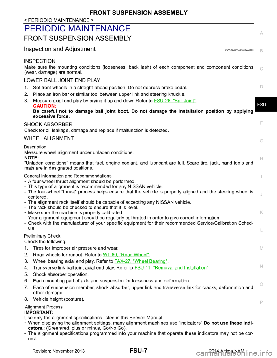
PERIODIC MAINTENANCE
FRONT SUSPENSION ASSEMBLY
Inspection and AdjustmentINFOID:0000000009460626
INSPECTION
Make sure the mounting conditions (looseness, back lash) of each component and component conditions
(wear, damage) are normal.
LOWER BALL JOINT END PLAY
1. Set front wheels in a straight-ahead position. Do not depress brake pedal.
2. Place an iron bar or similar tool between upper link and steering knuckle.
3. Measure axial end play by prying it up and down.Refer to FSU-26, "Ball Joint"
.
CAUTION:
Be careful not to damage ball joint boot. Do not damage the installation position by applying
excessive force.
SHOCK ABSORBER
Check for oil leakage, damage and repl ace if malfunction is detected.
WHEEL ALIGNMENT
Description
Measure wheel alignment under unladen conditions.
NOTE:
"Unladen conditions" means that fuel, engine coolant, and lubricant are full. Spare tire, jack, hand tools and
mats are in designated positions.
General Information and Recommendations
• A four-wheel thrust alignment should be performed.
- This type of alignment is re commended for any NISSAN vehicle.
- The four-wheel "thrust" process helps ensure that t he vehicle is properly aligned and the steering wheel is
centered.
- The alignment rack itself should be capable of accepting any NISSAN vehicle.
- The rack should be checked to ensure that it is level.
• Make sure the machine is properly calibrated.
- Your alignment equipment should be regularly ca librated in order to give correct information.
- Check with the manufacturer of your specific equi pment for their recommended Service/Calibration Sched-
ule.
Preliminary Check
Check the following:
1. Tires for improper air pressure and wear.
2. Road wheels for runout. Refer to WT-60, "Road Wheel"
.
3. Wheel bearing axial end play. Refer to FAX-27, "Wheel Bearing"
.
4. Transverse link ball joint axial end play. Refer to FSU-11, "Removal and Installation"
.
5. Shock absorber operation.
6. Each mounting part of axle and suspension for looseness and deformation.
7. Each of suspension member, shock absorber, upper link and transverse link for cracks, deformation and other damage.
8. Vehicle height (posture).
Alignment Process
IMPORTANT:
Use only the alignment specificati ons listed in this Service Manual.
• When displaying the alignment settings, m any alignment machines use "indicators" Do not use these indi-
cators. : (Green/red, plus or minus, Go/No Go).
- The alignment specifications programmed into your machine that operate these indicators may not be cor-
rect.
Revision: November 20132014 Altima NAM
Page 2529 of 4801
GI-1
GENERAL INFORMATION
C
D E
F
G H
I
J
K L
M B
GI
SECTION GI
N
O P
CONTENTS
GENERAL INFORMATION
HOW TO USE THIS MANU AL ......................3
HOW TO USE THIS MANUAL ....................... .....3
Description .......................................................... ......3
Terms ........................................................................3
Units ..........................................................................3
Contents ....................................................................3
Relation between Illustrations and Descriptions .......4
Components ..............................................................4
HOW TO FOLLOW TROUBLE DIAGNOSES .....6
Description ................................................................6
How to Follow Test Groups in Trouble Diagnosis ......6
Key to Symbols Signifying Measurements or Pro-
cedures ............................................................... ......
7
HOW TO READ WIRING DIAGRAMS ................9
Connector symbols ............................................. ......9
Sample/wiring diagram -example- ...........................10
Description ..............................................................11
ABBREVIATIONS .......................................... ....13
Abbreviation List .................................................. ....13
TIGHTENING TORQUE OF STANDARD
BOLTS ............................................................ ....
18
Description .......................................................... ....18
Tightening Torque Table (New Standard Includ-
ed) ....................................................................... ....
18
RECOMMENDED CHEMICAL PRODUCTS
AND SEALANTS ............................................ ....
21
Recommended Chemical Products and Sealants ....21
VEHICLE INFORMATION ............................22
IDENTIFICATION INFORMATION ................. ....22
Model Variation ................................................... ....22
Identification Number ..............................................23
Identification Plate ...................................................24
Engine Serial Number .............................................24
CVT Number ...........................................................25
Dimensions .......................................................... ....25
Wheels & Tires ........................................................25
PRECAUTION ..............................................26
PRECAUTIONS .................................................26
Description ........................................................... ....26
Precaution for Supplemental Restraint System
(SRS) "AIR BAG" and "SEAT BELT PRE-TEN-
SIONER" ............................................................. ....
26
Precautions For Xenon Headlamp Service .............26
Procedures without Cowl Top Cover .......................27
Cautions in Removing Battery Terminal and AV
Control Unit .......................................................... ....
27
General Precautions ................................................27
Three Way Catalyst .................................................29
Fuel (Regular Unleaded Gasoline Recommend-
ed) QR25DE ........................................................ ....
29
Fuel (Regular Unleaded Gasoline Recommend-
ed) VQ35DE ........................................................ ....
29
Multiport Fuel Injection System or Engine Control
System ................................................................. ....
29
Hoses ......................................................................29
Engine Oils ..............................................................30
Air Conditioning .......................................................31
LIFTING POINT .................................................32
Special Service Tool ................................................32
Pantograph Jack ......................................................32
Garage Jack and Safety Stand ................................33
2-Pole Lift ................................................................34
Board-on Lift ............................................................35
TOW TRUCK TOWING .....................................36
Tow Truck Towing ...................................................36
Vehicle Recovery (Freeing a Stuck Vehicle) ...........36
WIRING DIAGRAM ......................................38
CONSULT CHECKING SYSTEM .....................38
Wiring Diagram .................................................... ....38
Revision: November 20132014 Altima NAMRevision: November 20132014 Altima NAM
Page 2556 of 4801
GI-28
< PRECAUTION >
PRECAUTIONS
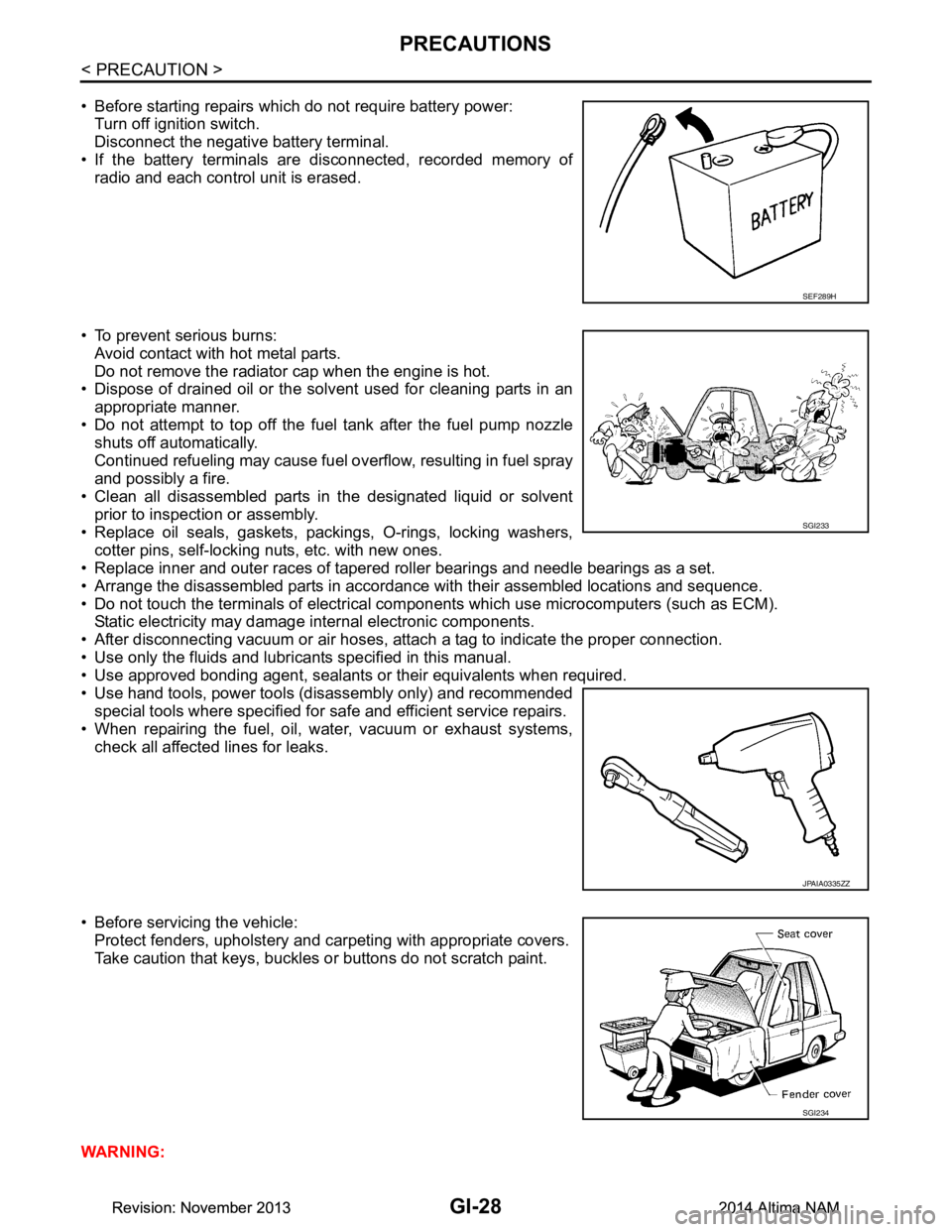
• Before starting repairs which do not require battery power:Turn off ignition switch.
Disconnect the negative battery terminal.
• If the battery terminals are disconnected, recorded memory of
radio and each control unit is erased.
• To prevent serious burns: Avoid contact with hot metal parts.
Do not remove the radiator cap when the engine is hot.
• Dispose of drained oil or the solvent used for cleaning parts in an
appropriate manner.
• Do not attempt to top off the fuel tank after the fuel pump nozzle
shuts off automatically.
Continued refueling may cause fuel overflow, resulting in fuel spray
and possibly a fire.
• Clean all disassembled parts in the designated liquid or solvent
prior to inspection or assembly.
• Replace oil seals, gaskets, packings, O-rings, locking washers, cotter pins, self-locking nuts, etc. with new ones.
• Replace inner and outer races of tapered roller bearings and needle bearings as a set.
• Arrange the disassembled parts in accordance with their assembled locations and sequence.
• Do not touch the terminals of electrical com ponents which use microcomputers (such as ECM).
Static electricity may damage internal electronic components.
• After disconnecting vacuum or air hoses, atta ch a tag to indicate the proper connection.
• Use only the fluids and lubricants specified in this manual.
• Use approved bonding agent, sealants or their equivalents when required.
• Use hand tools, power tools (disassembly only) and recommended special tools where specified for safe and efficient service repairs.
• When repairing the fuel, oil, water, vacuum or exhaust systems,
check all affected lines for leaks.
• Before servicing the vehicle: Protect fenders, upholstery and carpeting with appropriate covers.
Take caution that keys, buckles or buttons do not scratch paint.
WARNING:
SEF289H
SGI233
JPAIA0335ZZ
SGI234
Revision: November 20132014 Altima NAMRevision: November 20132014 Altima NAM
Page 2610 of 4801

HA-4
< PRECAUTION >
PRECAUTIONS
• Use only specified oil for the HFC-134a (R-134a) A/C system and HFC-134a (R-134a) components. If
oil other than that specified is used , compressor failure is likely to occur.
• The specified HFC-134a (R-134a) oi l rapidly absorbs moisture from the atmosphere. The following
handling precautions must be observed:
- When removing refrigerant components from a vehicle, immediately cap (seal) the component to
minimize the entry of moisture from the atmosphere.
- When installing refrigerant co mponents to a vehicle, do not remove the caps (unseal) until just
before connecting the components . Connect all refrigerant loop components as quickly as possible
to minimize the entry of moisture into system.
- Only use the specified oil from a sealed container. Immediately reseal containers of oil. Without
proper sealing, oil will become moisture saturat ed and should not be used.
- Avoid breathing A/C refrigerant and oil vapor or mist. Exposure may irritate eyes, nose and throat.
Remove HFC-134a (R-134a) from the A/C system usin g certified service equipment meeting require-
ments of SAE J2210 [HFC-134a (R-134a) recycling equipment], or J2209 [HFC-134a (R-134a) recy-
cling equipment], If accidental system discharge occurs, ventilate work area before resuming
service. Additional health and safety information may be obtain ed from refrigerant and oil manufac-
turers.
- Do not allow A/C oil to come in contact with styrofoam parts. Damage may result.
Contaminated RefrigerantINFOID:0000000009463911
If a refrigerant other than pure HFC-134a (R-134a) is identified in a vehicle, your options are:
• Explain to the customer that environmental regulations prohibit the release of contaminated refrigerant into
the atmosphere.
• Explain that recovery of the contaminated refri gerant could damage your service equipment and refrigerant
supply.
• Suggest the customer return the vehicle to the locati on of previous service where the contamination may
have occurred.
• If you choose to perform the repair, recover the refrigerant using only dedicated equipment and contain-
ers. Do not recover contamin ated refrigerant into your existing service equipment. If your facility does
not have dedicated recovery equipment, you may contact a local refrigerant product retailer for available ser-
vice. This refrigerant must be disposed of in acco rdance with all federal and local regulations. In addition,
replacement of all refrigerant system components on the vehicle is recommended.
• If the vehicle is within the warranty period, the air conditioner warranty is void. Please contact NISSAN Cus-
tomer Affairs for further assistance.
Precaution for Leak Detection DyeINFOID:0000000009463912
• The A/C system contains a fluorescent leak detection dye used for locating refrigerant leaks. An ultraviolet
(UV) lamp is required to illuminate the dye when inspecting for leaks.
• Always wear fluorescence enhancing UV safety goggles to protect your eyes and enhance the visibility of
the fluorescent dye.
• A compressor shaft seal should not be repaired because of dye seepage. The compressor shaft seal should only be repaired after confirming the leak with an electronic refrigerant leak detector (J-41995).
• Always remove any dye from the leak area after repairs are complete to avoid a misdiagnosis during a future
service.
• Do not allow dye to come into contact with painted body panels or interior components. If dye is spilled,
clean immediately with the approved dye cleaner. Fluoresc ent dye left on a surface for an extended period of
time cannot be removed .
• Do not spray the fluorescent dye cleaning agent on hot surfaces (engine exhaust manifold, etc.).
• Do not use more than one refrigerant dye bottle (1/4 ounce / 7.4 cc) per A/C system.
• Leak detection dyes for HFC-134a (R-134a) and HC-12 (R- 12) A/C systems are different. Do not use HFC-
134a (R-134a) leak detection dye in R-12 A/C systems or HC-12 (R-12) leak detection dye in HFC-134a (R-
134a) A/C systems or A/C system damage may result.
• The fluorescent properties of the dye will remain for ov er three (3) years unless a compressor failure occurs.
Precaution for Refrigerant ConnectionINFOID:0000000009463913
A new type refrigerant connection has been introduced to al l refrigerant lines except the following locations.
• Expansion valve to cooling unit
• Evaporator pipes to evaporator (inside cooling unit)
• Refrigerant pressure sensor
Revision: November 20132014 Altima NAM
Page 2613 of 4801
PRECAUTIONSHA-7
< PRECAUTION >
C
D E
F
G H
J
K L
M A
B
HA
N
O P
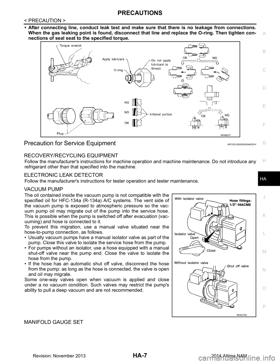
• After connecting line, conduct leak test and make sure that there is no leakage from connections.
When the gas leaking point is f ound, disconnect that line and replace the O-ring. Then tighten con-
nections of seal seat to the specified torque.
Precaution for Service EquipmentINFOID:0000000009463914
RECOVERY/RECYCLING EQUIPMENT
Follow the manufacturer's instructions for machine operation and machine maintenance. Do not introduce any
refrigerant other than that specified into the machine.
ELECTRONIC LEAK DETECTOR
Follow the manufacturer's instructions fo r tester operation and tester maintenance.
VACUUM PUMP
The oil contained inside the vacuum pump is not compatible with the
specified oil for HFC-134a (R-134a) A/C systems. The vent side of
the vacuum pump is exposed to atmospheric pressure so the vac-
uum pump oil may migrate out of the pump into the service hose.
This is possible when the pump is switched off after evacuation (vac-
uuming) and hose is connected to it.
To prevent this migration, use a manual valve situated near the
hose-to-pump connection, as follows.
• Usually vacuum pumps have a manual isolator valve as part of the
pump. Close this valve to isolate the service hose from the pump.
• For pumps without an isolator, use a hose equipped with a manual shut-off valve near the pump end. Close the valve to isolate the
hose from the pump.
• If the hose has an automatic shut off valve, disconnect the hose from the pump: as long as the hos e is connected, the valve is open
and oil may migrate.
Some one-way valves open when vacuum is applied and close
under a no vacuum condition. Such valves may restrict the pump's
ability to pull a deep vacuum and are not recommended.
MANIFOLD GAUGE SET
RHA861F
RHA270D
Revision: November 20132014 Altima NAM
Page 2614 of 4801
HA-8
< PRECAUTION >
PRECAUTIONS
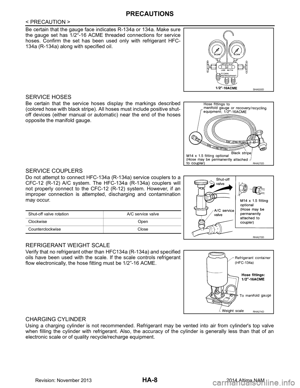
Be certain that the gauge face indicates R-134a or 134a. Make sure
the gauge set has 1/2 ″-16 ACME threaded connections for service
hoses. Confirm the set has been used only with refrigerant HFC-
134a (R-134a) along with specified oil.
SERVICE HOSES
Be certain that the service hoses display the markings described
(colored hose with black stripe). All hoses must include positive shut-
off devices (either manual or aut omatic) near the end of the hoses
opposite the manifold gauge.
SERVICE COUPLERS
Do not attempt to connect HFC-134a (R-134a) service couplers to a
CFC-12 (R-12) A/C system. The HFC-134a (R-134a) couplers will
not properly connect to the CFC-12 (R-12) system. However, if an
improper connection is attempted, discharging and contamination
may occur.
REFRIGERANT WEIGHT SCALE
Verify that no refrigerant other than HFC134a (R-134a) and specified
oils have been used with the scale. If the scale controls refrigerant
flow electronically, the hose fitting must be 1/2”-16 ACME.
CHARGING CYLINDER
Using a charging cylinder is not recommended. Refrigerant may be vented into air from cylinder's top valve
when filling the cylinder with refrigerant. Also, the accu racy of the cylinder is generally less than that of an
electronic scale or of quality recycle/recharge equipment.
SHA533D
RHA272D
Shut-off valve rotati on A/C service valve
Clockwise Open
Counterclockwise Close
RHA273D
RHA274D
Revision: November 20132014 Altima NAM