2014 NISSAN TEANA fuel filter
[x] Cancel search: fuel filterPage 2000 of 4801

EM-2
Exploded View ........................................................41
Removal and Installation ........................................41
ROCKER COVER ..............................................45
Exploded View ..................................................... ...45
Removal and Installation ........................................45
CAMSHAFT .......................................................47
Exploded View ..................................................... ...47
Removal and Installation ........................................47
Inspection After Installation ................................. ...56
VALVE TIMING CONTROL ............................ ...58
Exploded View ..................................................... ...58
Intake Valve Timing Intermediate Lock Control
Solenoid Valve, Intake Va lve Timing Control Sole-
noid Valve, and Exhaust Valve Timing Control So-
lenoid Valve ......................................................... ...
58
Valve Timing Control Cover ....................................59
TIMING CHAIN ............................................... ...61
Exploded View ..................................................... ...61
Removal and Installation ........................................62
OIL SEAL ...........................................................70
Removal and Installation of Valve Oil Seal .......... ...70
Removal and Installation of Front Oil Seal .............71
Removal and Installation of Rear Oil Seal ..............72
CYLINDER HEAD ..............................................74
Exploded View ..................................................... ...74
Removal and Installation ........................................74
Disassembly and Assembly ....................................76
Inspection After Disassembly .................................78
UNIT REMOVAL AND INSTALLATION .. ...83
ENGINE ASSEMBLY ...................................... ...83
Exploded View ..................................................... ...83
Removal and Installation ........................................84
UNIT DISASSEMBLY AND ASSEMBLY ....87
CYLINDER BLOCK ........................................ ...87
Exploded View ..................................................... ...87
Disassembly and Assembly ....................................88
Inspection After Disassembly .................................96
HOW TO SELECT PISTON AND BEARING .. .105
How to Select Piston and Bearing ....................... ..105
SERVICE DATA AND SPECIFICATIONS
(SDS) .............. ............................................
111
SERVICE DATA AND SPECIFICATIONS
(SDS) ............................................................... .
111
Standard and Limit .............................................. ..111
VQ35DE
PRECAUTION .............. ..............................
123
PRECAUTIONS .............................................. .123
Precaution for Supplemental Restraint System
(SRS) "AIR BAG" and "SEAT BELT PRE-TEN-
SIONER" .............................................................. .
123
Precaution for Draining Coolant ............................123
Precaution for Disconnecting Fuel Piping .............123
Precaution for Removal and Disassembly ............123
Precaution for Inspection, Repair and Replace-
ment ..................................................................... .
123
Precaution for Assembly and Installation ..............123
Parts Requiring Angular Tightening ..................... .124
Precaution for Liquid Gasket .................................124
PREPARATION .........................................126
PREPARATION .............................................. ..126
Special Service Tool ............................................ .126
Commercial Service Tool ......................................127
SYSTEM DESCRIPTION ..........................130
NOISE, VIBRATION, AND HARSHNESS
(NVH) TROUBLESHOOTING ......................... ..
130
NVH Troubleshooting - Engine Noise .................. .130
Use the Chart Below to Help You Find the Cause
of the Symptom .................................................... .
131
PERIODIC MAINTENANCE ......................132
SPARK PLUG ... .............................................. ..132
Exploded View ..................................................... .132
Removal and Installation .......................................132
DRIVE BELTS ................................................ ..134
Exploded View ..................................................... .134
Checking Drive Belts .............................................134
Tension Adjustment ..............................................134
Removal and Installation .......................................134
Removal and Installation of Drive Belt Auto-ten-
sioner ................................................................... .
135
AIR CLEANER FILTER ....................................137
Exploded View ..................................................... .137
Removal and Installation .......................................137
CAMSHAFT VALVE CLEARANCE ............... ..138
Valve Clearance ................................................... .138
COMPRESSION PRESSURE ..........................142
On-Vehicle Service .............................................. .142
REMOVAL AND INSTALLATION .............143
ENGINE ROOM COVER ................................ ..143
Exploded View ..................................................... .143
Removal and Installation .......................................143
AIR CLEANER AND AIR DUCT ..................... ..144
Exploded View ..................................................... .144
Removal and Installation .......................................144
INTAKE MANIFOLD COLLECTOR ............... ..146
Exploded View ..................................................... .146
Revision: November 20132014 Altima NAM
Page 2481 of 4801
FL-1
ENGINE
C
D E
F
G H
I
J
K L
M
SECTION FL
A
FL
N
O P
CONTENTS
FUEL SYSTEM
PRECAUTION ................ ...............................2
PRECAUTIONS .............................................. .....2
Precaution for Supplemental Restraint System
(SRS) "AIR BAG" and "SEAT BELT PRE-TEN-
SIONER" ............................................................. ......
2
General Precaution ...................................................2
PREPARATION ............................................4
PREPARATION .............................................. .....4
Special Service Tool ........................................... ......4
Commercial Service Tool ..........................................4
PERIODIC MAINTENANCE ..........................5
FUEL SYSTEM ............................................... .....5
Inspection ............................................................ ......5
Quick Connector .......................................................5
REMOVAL AND INSTALLATION ................6
FUEL LEVEL SENSOR UNIT, FUEL FILTER
AND FUEL PUMP ASSEMBLY ..................... .....
6
Exploded View .................................................... ......6
Removal and Installation ...........................................6
Inspection ............................................................ ......9
FUEL TANK ........................................................10
Exploded View .................................................... ....10
Removal and Installation .........................................10
Inspection ............................................................ ....13
EVAP CANISTER ..............................................14
Exploded View .........................................................14
Removal and Installation .........................................14
Inspection ................................................................15
EVAP CANISTER FILTER ................................16
Exploded View .........................................................16
Removal and Installation .........................................16
EVAP CANISTER VENT CONTROL VALVE ...17
Exploded View .........................................................17
Removal and Installation .........................................17
EVAP CONTROL SYSTEM PRESSURE SEN-
SOR ...................................................................
18
Exploded View ..................................................... ....18
Removal and Installation .........................................18
UNIT DISASSEMBLY AND ASSEMBLY ....19
FUEL LEVEL SENSOR UNIT ...........................19
Disassembly and Assembly ................................. ....19
SERVICE DATA AND SPECIFICATIONS
(SDS) ............... .............................................
21
SERVICE DATA AND SPECIFICATIONS
(SDS) .................................................................
21
Fuel Tank ............................................................. ....21
Revision: November 20132014 Altima NAM
Page 2486 of 4801
FL-6
< REMOVAL AND INSTALLATION >
FUEL LEVEL SENSOR UNIT, FUEL FILTER AND FUEL PUMP ASSEMBLY
REMOVAL AND INSTALLATION
FUEL LEVEL SENSOR UNIT, FUEL FILTER AND FUEL PUMP ASSEMBLY
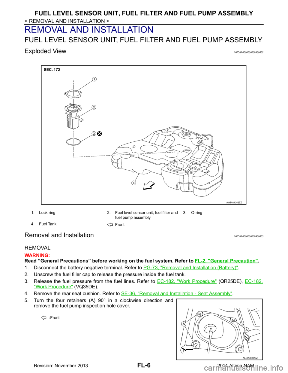
Exploded ViewINFOID:0000000009460602
Removal and InstallationINFOID:0000000009460603
REMOVAL
WARNING:
Read “General Precautions” before wo rking on the fuel system. Refer to FL-2, "General Precaution"
.
1. Disconnect the battery negative terminal. Refer to PG-73, "Removal and Installation (Battery)"
.
2. Unscrew the fuel filler cap to release the pressure inside the fuel tank.
3. Release the fuel pressure from the fuel lines. Refer to EC-182, "Work Procedure"
(QR25DE), EC-182,
"Work Procedure" (VQ35DE).
4. Remove the rear seat cushion. Refer to SE-36, "Removal and Installation - Seat Assembly"
.
5. Turn the four retainers (A) 90 ° in a clockwise direction and
remove the fuel pump inspection hole cover.
1. Lock ring 2. Fuel level sensor unit, fuel filter and
fuel pump assembly3. O-ring
4. Fuel Tank Front
AWBIA1345ZZ
:Front
ALBIA0892ZZ
Revision: November 20132014 Altima NAM
Page 2487 of 4801
FUEL LEVEL SENSOR UNIT, FUEL FILTER AND FUEL PUMP ASSEMBLYFL-7
< REMOVAL AND INSTALLATION >
C
D E
F
G H
I
J
K L
M A
FL
NP
O
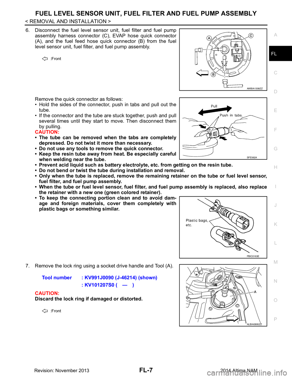
6. Disconnect the fuel level sensor unit, fuel filter and fuel pump
assembly harness connector (C), EVAP hose quick connector
(A), and the fuel feed hose quick connector (B) from the fuel
level sensor unit, fuel filter, and fuel pump assembly.
Remove the quick connector as follows:
• Hold the sides of the connector, push in tabs and pull out the
tube.
• If the connector and the tube are stuck together, push and pull several times until they start to move. Then disconnect them
by pulling.
CAUTION:
• The tube can be removed when the tabs are completely
depressed. Do not twist it more than necessary.
• Do not use any tools to remove the quick connector.
• Keep the resin tube away from heat. Be especially careful
when welding near the tube.
• Prevent acid liquid such as battery electroly te, etc. from getting on the resin tube.
• Do not bend or twist the tube during installation and removal.
• Only when the tube is replaced, remove the remaining retainer on the tube or fuel level sensor,
fuel filter, and fuel pump assembly.
• When the tube or fuel level sen sor, fuel filter, and fuel pump assembly is replaced, also replace
the retainer with a new one (green colored retainer).
• To keep the connecting portio n clean and to avoid dam-
age and foreign materials, cover them completely with
plastic bags or something similar.
7. Remove the lock ring using a socket drive handle and Tool (A). CAUTION:
Discard the lock ring if damaged or distorted.
:Front
AWBIA1308ZZ
SFE562A
PBIC0163E
Tool number : KV991J0090 (J-46214) (shown)
: KV101207S0 ( — )
:Front
ALBIA0895ZZ
Revision: November 20132014 Altima NAM
Page 2488 of 4801
FL-8
< REMOVAL AND INSTALLATION >
FUEL LEVEL SENSOR UNIT, FUEL FILTER AND FUEL PUMP ASSEMBLY
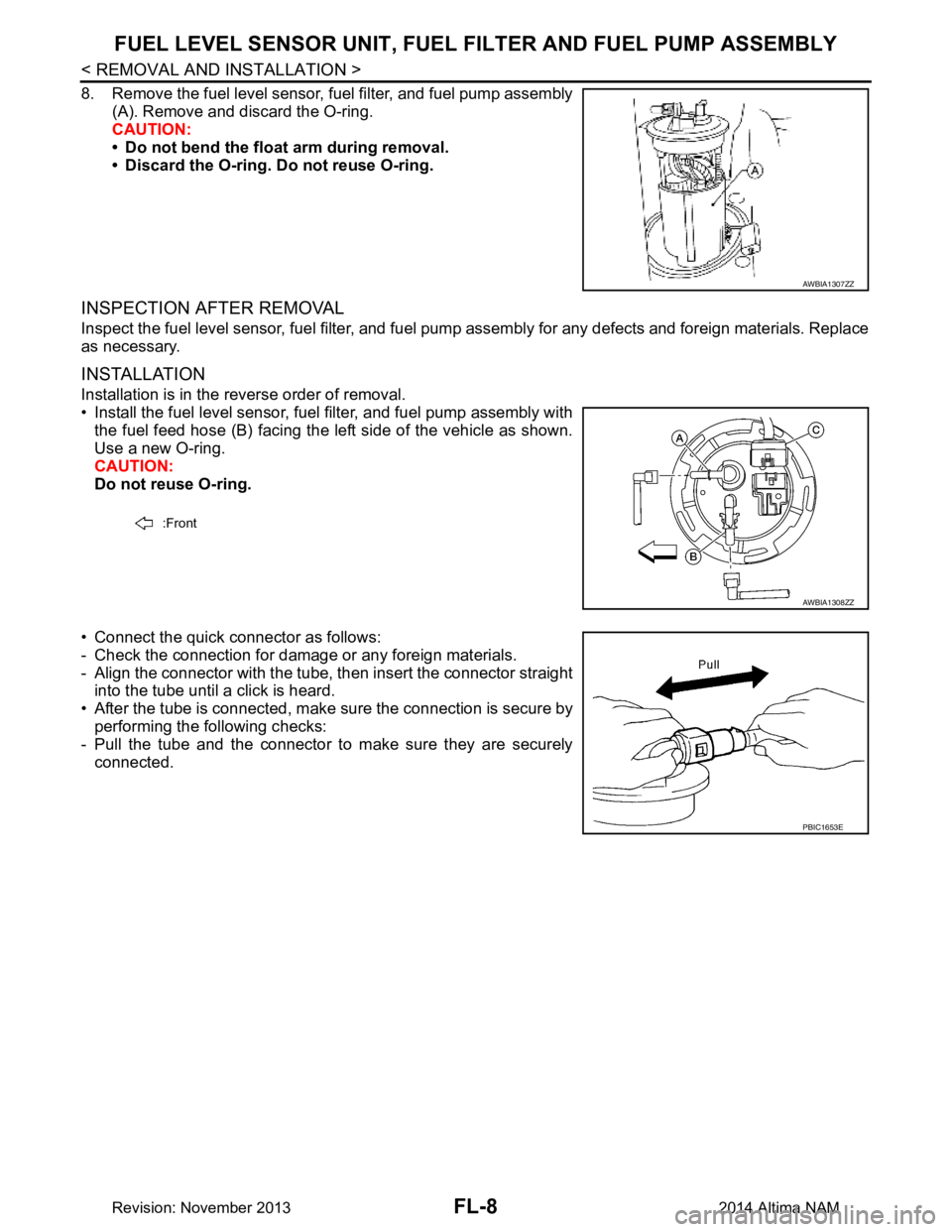
8. Remove the fuel level sensor, fuel filter, and fuel pump assembly
(A). Remove and discard the O-ring.
CAUTION:
• Do not bend the float arm during removal.
• Discard the O-ring. Do not reuse O-ring.
INSPECTION AFTER REMOVAL
Inspect the fuel level sensor, fuel filter, and fuel pump assembly for any defects and foreign materials. Replace
as necessary.
INSTALLATION
Installation is in the reverse order of removal.
• Install the fuel level sensor, fuel filter, and fuel pump assembly with the fuel feed hose (B) facing the left side of the vehicle as shown.
Use a new O-ring.
CAUTION:
Do not reuse O-ring.
• Connect the quick connector as follows:
- Check the connection for damage or any foreign materials.
- Align the connector with the tube, then insert the connector straight into the tube until a click is heard.
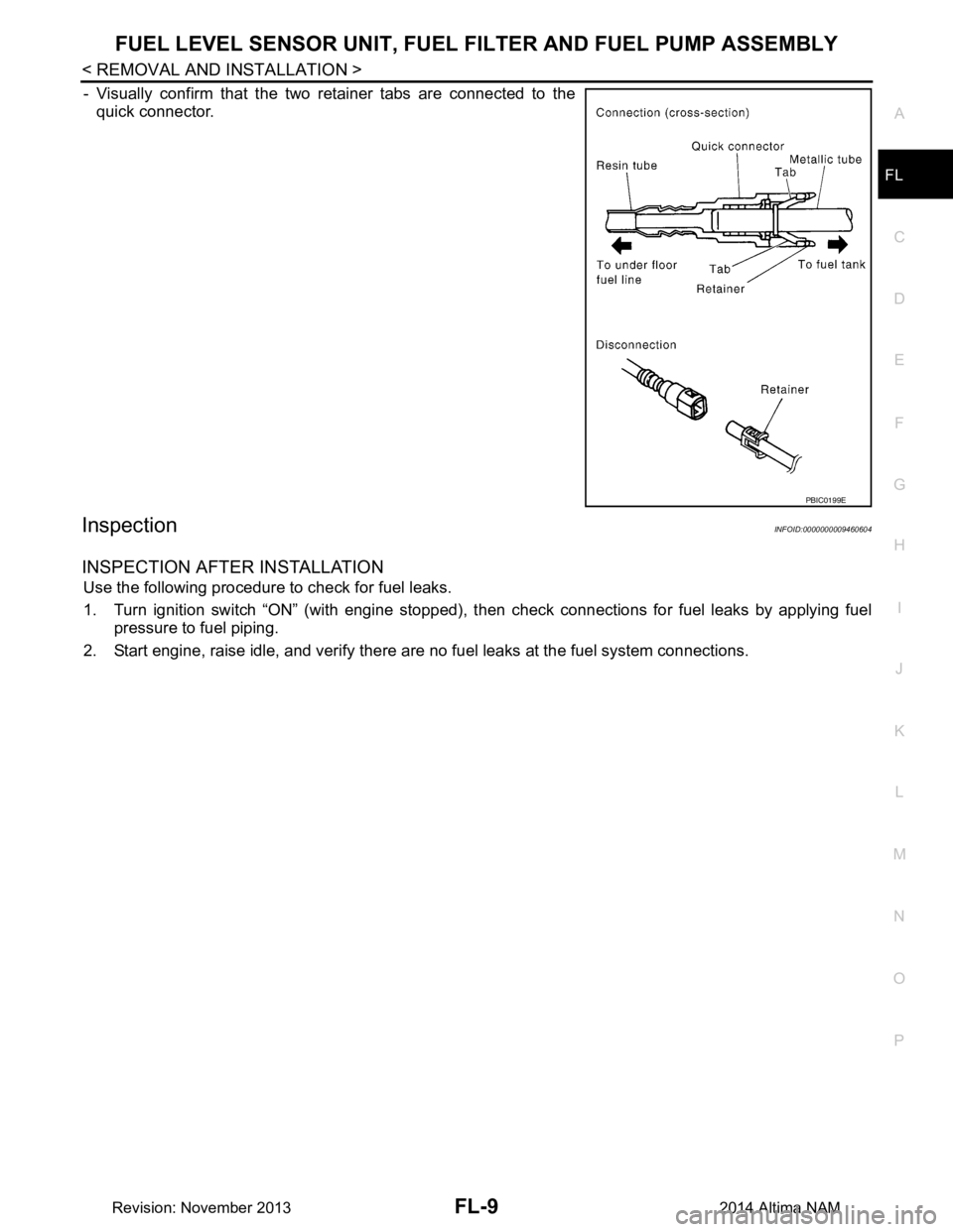
• After the tube is connected, make sure the connection is secure by performing the following checks:
- Pull the tube and the connector to make sure they are securely
connected.
AWBIA1307ZZ
:Front
AWBIA1308ZZ
PBIC1653E
Revision: November 20132014 Altima NAM
Page 2489 of 4801
FUEL LEVEL SENSOR UNIT, FUEL FILTER AND FUEL PUMP ASSEMBLYFL-9
< REMOVAL AND INSTALLATION >
C
D E
F
G H
I
J
K L
M A
FL
NP
O
- Visually confirm that the two retainer tabs are connected to the
quick connector.
InspectionINFOID:0000000009460604
INSPECTION AFTER INSTALLATION
Use the following procedure to check for fuel leaks.
1. Turn ignition switch “ON” (with engine stopped), t hen check connections for fuel leaks by applying fuel
pressure to fuel piping.
2. Start engine, raise idle, and verify there are no fuel leaks at the fuel system connections.
PBIC0199E
Revision: November 20132014 Altima NAM
Page 2490 of 4801
FL-10
< REMOVAL AND INSTALLATION >
FUEL TANK
FUEL TANK
Exploded ViewINFOID:0000000009460605
Removal and InstallationINFOID:0000000009460606
REMOVAL
WARNING:
Read “General Precautions” before wo rking on the fuel system. Refer to FL-2, "General Precaution"
.
NOTE:
When removing components such as hoses, tubes/lines, etc. , cap or plug openings to prevent fluid from spill-
ing.
1. Disconnect the battery negative terminal. Refer to PG-73, "Removal and Installation (Battery)"
.
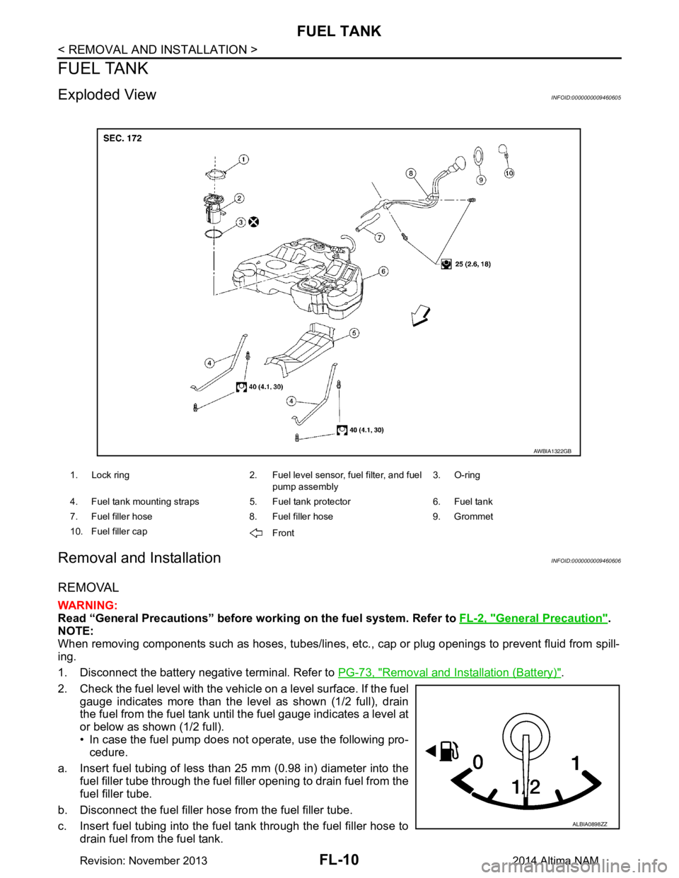
2. Check the fuel level with the vehicle on a level surface. If the fuel gauge indicates more than the level as shown (1/2 full), drain
the fuel from the fuel tank until the fuel gauge indicates a level at
or below as shown (1/2 full).
• In case the fuel pump does not operate, use the following pro- cedure.
a. Insert fuel tubing of less than 25 mm (0.98 in) diameter into the fuel filler tube through the fuel f iller opening to drain fuel from the
fuel filler tube.
b. Disconnect the fuel filler hose from the fuel filler tube.
c. Insert fuel tubing into the fuel tank through the fuel filler hose to drain fuel from the fuel tank.
1. Lock ring 2. Fuel level sensor, fuel filter, and fuel
pump assembly3. O-ring
4. Fuel tank mounting straps 5. Fuel tank protector 6. Fuel tank
7. Fuel filler hose 8. Fuel filler hose 9. Grommet
10. Fuel filler cap Front
AWBIA1322GB
ALBIA0898ZZ
Revision: November 20132014 Altima NAM
Page 2491 of 4801
FUEL TANKFL-11
< REMOVAL AND INSTALLATION >
C
D E
F
G H
I
J
K L
M A
FL
NP
O
• As a guide, if the fuel tank is full the fuel leve
l reaches or is less than the level on the fuel gauge as
shown, when approximately 34 (9 US gal, 7 1/2 Imp gal) of fuel is drained from a full fuel tank.
3. Open the fuel filler cap to release the pressure inside the fuel tank.
4. Release fuel pressure from fuel line. Refer to EC-182, "Work Procedure"
(QR25DE), EC-687, "Work Pro-
cedure" (VQ35DE).
5. Remove rear seat cushion. Refer to SE-36, "Removal and Installation - Seat Assembly"
.
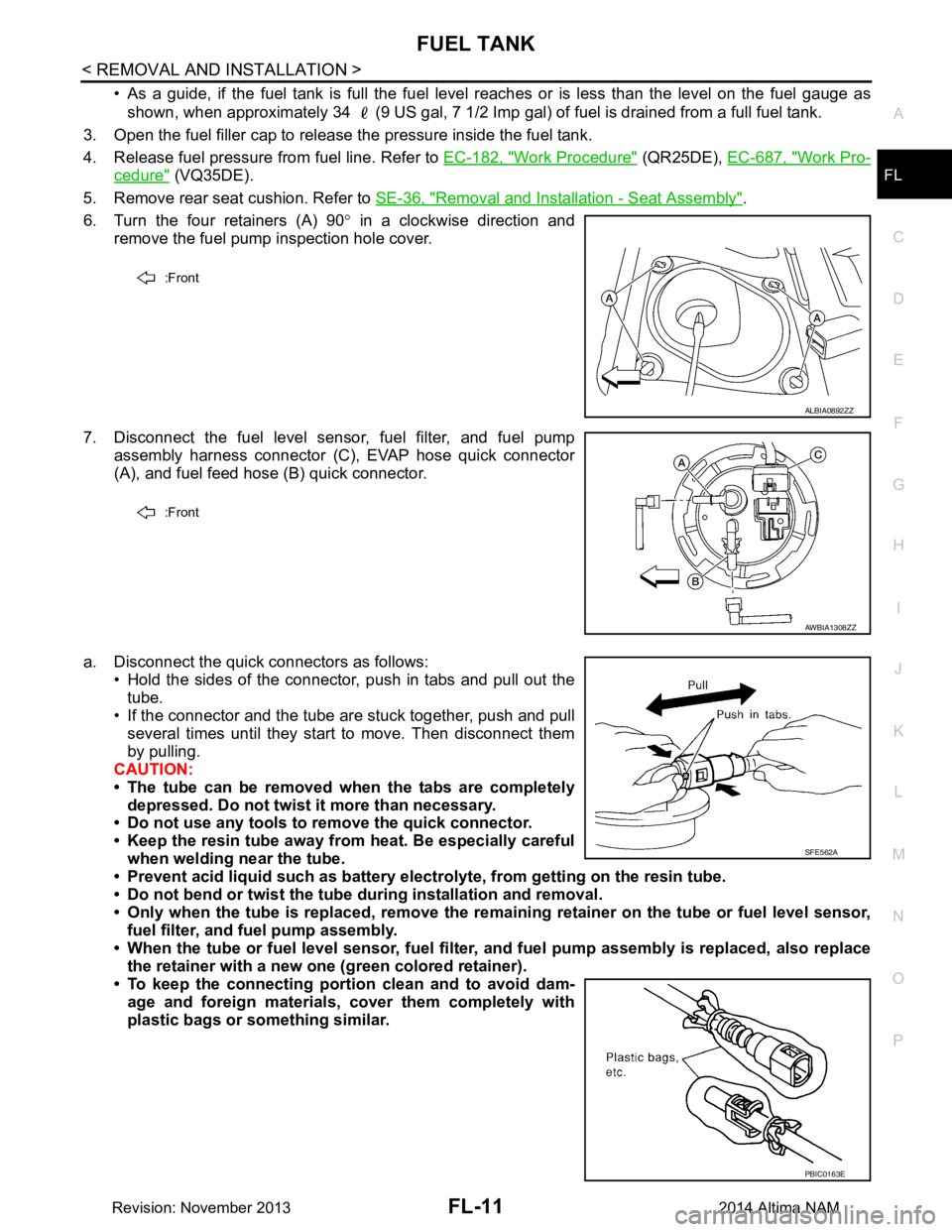
6. Turn the four retainers (A) 90 ° in a clockwise direction and
remove the fuel pump inspection hole cover.
7. Disconnect the fuel level sensor, fuel filter, and fuel pump assembly harness connector (C), EVAP hose quick connector
(A), and fuel feed hose (B) quick connector.
a. Disconnect the quick connectors as follows: • Hold the sides of the connector, push in tabs and pull out the
tube.
• If the connector and the tube are stuck together, push and pull
several times until they start to move. Then disconnect them
by pulling.
CAUTION:
• The tube can be removed when the tabs are completely depressed. Do not twist it more than necessary.
• Do not use any tools to remove the quick connector.
• Keep the resin tube away from heat. Be especially careful
when welding near the tube.
• Prevent acid liquid such as battery elect rolyte, from getting on the resin tube.
• Do not bend or twist the tube during installation and removal.
• Only when the tube is replaced, remove the remaining retainer on the tube or fuel level sensor,
fuel filter, and fuel pump assembly.
• When the tube or fuel level sen sor, fuel filter, and fuel pump assembly is replaced, also replace
the retainer with a new one (green colored retainer).
• To keep the connecting portio n clean and to avoid dam-
age and foreign materials, cover them completely with
plastic bags or something similar.
:Front
ALBIA0892ZZ
:Front
AWBIA1308ZZ
SFE562A
PBIC0163E
Revision: November 20132014 Altima NAM