2014 NISSAN TEANA stop start
[x] Cancel search: stop startPage 3702 of 4801
SQUEAK AND RATTLE TROUBLE DIAGNOSESRF-37
< SYMPTOM DIAGNOSIS >
C
D E
F
G H
I
J
L
M A
B
RF
N
O P
Used instead of UHMW tape that will be visible or not fit.
Note: Will only last a few months.
SILICONE SPRAY
Use when grease cannot be applied.
DUCT TAPE
Use to eliminate movement.
CONFIRM THE REPAIR
Confirm that the cause of a noise is repaired by test driving the vehicle. Operate the vehicle under the same
conditions as when the noise originally occurred. Refer to the notes on the Diagnostic Worksheet.
Generic Squeak and Rattle TroubleshootingINFOID:0000000009461322
Refer to Table of Contents for specific component removal and installation information.
INSTRUMENT PANEL
Most incidents are caused by contact and movement between:
1. Cluster lid A and the instrument panel
2. Acrylic lens and combination meter housing
3. Instrument panel to front pillar finisher
4. Instrument panel to windshield
5. Instrument panel pins
6. Wiring harnesses behind the combination meter
7. A/C defroster duct and duct joint
These incidents can usually be located by tapping or moving the components to duplicate the noise or by
pressing on the components while driving to stop the noi se. Most of these incidents can be repaired by apply-
ing felt cloth tape or silicone spray (in hard to reach areas). Urethane pads can be used to insulate wiring har-
ness.
CAUTION:
Do not use silicone spray to isolate a squeak or ra ttle. If you saturate the area with silicone, you will
not be able to recheck the repair.
CENTER CONSOLE
Components to pay attention to include:
1. Shift selector assembly cover to finisher
2. A/C control unit and cluster lid C
3. Wiring harnesses behind audio and A/C control unit
The instrument panel repair and isolation pr ocedures also apply to the center console.
DOORS
Pay attention to the:
1. Finisher and inner panel making a slapping noise
2. Inside handle escutcheon to door finisher
3. Wiring harnesses tapping
4. Door striker out of alignment causing a popping noise on starts and stops
Tapping or moving the components or pressing on them wh ile driving to duplicate the conditions can isolate
many of these incidents. You can usually insulate the ar eas with felt cloth tape or insulator foam blocks from
the NISSAN Squeak and Rattle Kit (J-43980) to repair the noise.
TRUNK
Trunk noises are often caused by a loose jack or loose items put into the trunk by the owner.
In addition look for:
1. Trunk lid bumpers out of adjustment
2. Trunk lid striker out of adjustment
3. The trunk lid torsion bars knocking together
4. A loose license plate or bracket
Revision: November 20132014 Altima NAMRevision: November 20132014 Altima NAM
Page 3768 of 4801
SQUEAK AND RATTLE TROUBLE DIAGNOSESSE-19
< SYMPTOM DIAGNOSIS >
C
D E
F
G H
I
K L
M A
B
SE
N
O P
INSTRUMENT PANEL
Most incidents are caused by contact and movement between:
1. Cluster lid A and the instrument panel
2. Acrylic lens and combination meter housing
3. Instrument panel to front pillar finisher
4. Instrument panel to windshield
5. Instrument panel pins
6. Wiring harnesses behind the combination meter
7. A/C defroster duct and duct joint
These incidents can usually be located by tapping or moving the components to duplicate the noise or by
pressing on the components while driving to stop the noi se. Most of these incidents can be repaired by apply-
ing felt cloth tape or silicone spray (in hard to reach areas). Urethane pads can be used to insulate wiring har-
ness.
CAUTION:
Do not use silicone spray to isolate a squeak or ra ttle. If you saturate the area with silicone, you will
not be able to recheck the repair.
CENTER CONSOLE
Components to pay attention to include:
1. Shift selector assembly cover to finisher
2. A/C control unit and cluster lid C
3. Wiring harnesses behind audio and A/C control unit
The instrument panel repair and isolation pr ocedures also apply to the center console.
DOORS
Pay attention to the:
1. Finisher and inner panel making a slapping noise
2. Inside handle escutcheon to door finisher
3. Wiring harnesses tapping
4. Door striker out of alignment causing a popping noise on starts and stops
Tapping or moving the components or pressing on them wh ile driving to duplicate the conditions can isolate
many of these incidents. You can usually insulate the ar eas with felt cloth tape or insulator foam blocks from
the NISSAN Squeak and Rattle Kit (J-50397) to repair the noise.
TRUNK
Trunk noises are often caused by a loose jack or loose items put into the trunk by the owner.
In addition look for:
1. Trunk lid bumpers out of adjustment
2. Trunk lid striker out of adjustment
3. The trunk lid torsion bars knocking together
4. A loose license plate or bracket
Most of these incidents can be repaired by adjusting, se curing or insulating the item(s) or component(s) caus-
ing the noise.
SUNROOF/HEADLINING
Noises in the sunroof/headlining area can often be traced to one of the following:
1. Sunroof lid, rail, linkage or seals making a rattle or light knocking noise
2. Sun visor shaft shaking in the holder
3. Front or rear windshield touching headlining and squeaking
Again, pressing on the components to stop the noise while duplicating the conditions can isolate most of these
incidents. Repairs usually consist of insulating with felt cloth tape.
OVERHEAD CONSOLE (FRONT AND REAR)
Overhead console noises are often caused by the cons ole panel clips not being engaged correctly. Most of
these incidents are repaired by pushing up on the c onsole at the clip locations until the clips engage.
In addition look for:
Revision: November 20132014 Altima NAMRevision: November 20132014 Altima NAM
Page 3826 of 4801

SEC-1
BODY EXTERIOR, DOORS, ROOF & VEHICLE SECURITY
C
D E
F
G H
I
J
L
M
SECTION SEC
A
B
SEC
N
O P
CONTENTS
SECURITY CONTROL SYSTEM
PRECAUTION ................ ...............................4
PRECAUTIONS .............................................. .....4
Precaution for Supplemental Restraint System
(SRS) "AIR BAG" and "SEAT BELT PRE-TEN-
SIONER" ............................................................. ......
4
Precaution for Work ..................................................4
PREPARATION ............................................5
PREPARATION .............................................. .....5
Special Service Tool ........................................... ......5
SYSTEM DESCRIPTION ..............................6
COMPONENT PARTS ................................... .....6
Component Parts Location .................................. ......6
Component Description .............................................8
CVT Shift Selector (Park Position Switch) ................8
BCM ..........................................................................8
ECM ..........................................................................8
IPDM E/R ..................................................................9
NATS Antenna Amp. .................................................9
TCM ..........................................................................9
Combination Meter ....................................................9
Door Switch ...............................................................9
Outside Key Antenna ................................................9
Hood Switch ..............................................................9
Inside Key Antenna ...................................................9
Remote Keyless Entry Receiver ...............................9
Intelligent Key ............................................................9
Push-button Ignition Switch .....................................10
Security Indicator Lamp ...................................... ....10
Starter Control Relay ...............................................10
Starter Relay ...........................................................10
Stop Lamp Switch ...................................................10
Transmission Range Switch ....................................10
Vehicle Information Display .....................................10
SYSTEM .............................................................11
INTELLIGENT KEY SYSTEM/ENGINE START
FUNCTION ............................................................. ....
11
INTELLIGENT KEY SYSTEM/ENGINE START
FUNCTION : System Diagram ............................ ....
11
INTELLIGENT KEY SYSTEM/ENGINE START
FUNCTION : System Description ........................ ....
11
NISSAN VEHICLE IMMOBILIZER SYSTEM-NATS ....13
NISSAN VEHICLE IMMOBILIZER SYSTEM-
NATS : System Diagram ..................................... ....
14
NISSAN VEHICLE IMMOBILIZER SYSTEM-
NATS : System Description ................................. ....
14
VEHICLE SECURITY SYSTEM .................................16
VEHICLE SECURITY SYSTEM : System Dia-
gram .................................................................... ....
16
VEHICLE SECURITY SYSTEM : System Descrip-
tion ....................................................................... ....
16
DIAGNOSIS SYSTEM (BCM) ...........................20
COMMON ITEM ..................................................... ....20
COMMON ITEM : CONSULT Function (BCM -
COMMON ITEM) ................................................. ....
20
INTELLIGENT KEY ................................................ ....21
INTELLIGENT KEY : CONSULT Function (BCM -
INTELLIGENT KEY) ........... .....................................
21
THEFT ALM ........................................................... ....24
THEFT ALM : CONSULT Function (BCM - THEFT
ALM) .................................................................... ....
24
IMMU ...................................................................... ....25
IMMU : CONSULT Function (BCM - IMMU) ............25
DIAGNOSIS SYSTEM (IPDM E/R) ...................26
CONSULT Function (IPDM E/R) .............................26
ECU DIAGNOSIS INFORMATION ..............28
ECM, IPDM E/R, BCM .......................................28
List of ECU Reference ......................................... ....28
Revision: November 20132014 Altima NAMRevision: November 20132014 Altima NAM
Page 3827 of 4801

SEC-2
WIRING DIAGRAM .....................................29
ENGINE START FUNCTION .......................... ...29
Wiring Diagram .................................................... ...29
NISSAN VEHICLE IMMOBILIZER SYSTEM-
NATS ............................................................... ...
40
Wiring Diagram .................................................... ...40
VEHICLE SECURITY SYSTEM .........................50
Wiring Diagram .................................................... ...50
BASIC INSPECTION ...................................63
DIAGNOSIS AND REPAIR WORK FLOW ..... ...63
Work Flow ............................................................ ...63
ADDITIONAL SERVICE WHEN REPLACING
CONTROL UNIT ............................................. ...
66
ECM ........................................................................ ...66
ECM : Description ...................................................66
ECM : Work Procedure ...........................................66
BCM ........................................................................ ...66
BCM : Description ...................................................66
BCM : Work Procedure ...........................................66
DTC/CIRCUIT DIAGNOSIS ...................... ...68
P1610 LOCK MODE ....................................... ...68
Description ........................................................... ...68
DTC Logic ...............................................................68
Diagnosis Procedure ..............................................68
P1611 ID DISCORD, IMMU-ECM ......................69
DTC Logic ............................................................ ...69
Diagnosis Procedure ..............................................69
P1612 CHAIN OF ECM-IMMU ...........................70
DTC Logic ............................................................ ...70
Diagnosis Procedure ..............................................70
P1614 CHAIN OF IMMU-KEY ...........................71
DTC Logic ............................................................ ...71
Diagnosis Procedure ..............................................71
B210B STARTER CONTROL RELAY ..............73
DTC Logic ............................................................ ...73
Diagnosis Procedure ..............................................73
B210C STARTER CONTROL RELAY ..............74
DTC Logic ............................................................ ...74
Diagnosis Procedure ..............................................74
B210D STARTER RELAY .................................76
DTC Logic ............................................................ ...76
Diagnosis Procedure ..............................................76
B210E STARTER RELAY .................................78
DTC Logic ............................................................ ...78
Diagnosis Procedure ..............................................78
B210F TRANSMISSION RANGE SWITCH .......80
Description ........................................................... ...80
DTC Logic ...............................................................80
Diagnosis Procedure ...............................................80
B2110 TRANSMISSION RANGE SWITCH .......82
Description ........................................................... ...82
DTC Logic ...............................................................82
Diagnosis Procedure ...............................................82
B2190 NATS ANTENNA AMP. .........................84
Description ........................................................... ...84
DTC Logic ...............................................................84
Diagnosis Procedure ...............................................84
B2191 DIFFERENCE OF KEY ..........................86
Description ........................................................... ...86
DTC Logic ...............................................................86
Diagnosis Procedure ...............................................86
B2192 ID DISCORD, IMMU-ECM ......................87
DTC Logic ............................................................ ...87
Diagnosis Procedure ...............................................87
B2193 CHAIN OF ECM-IMMU ..........................88
DTC Logic ............................................................ ...88
Diagnosis Procedure ...............................................88
B2195 ANTI-SCANNING ...................................89
DTC Logic ............................................................ ...89
Diagnosis Procedure ...............................................89
B2196 DONGLE UNIT .......................................90
Description ........................................................... ...90
DTC Logic ...............................................................90
Diagnosis Procedure ...............................................90
B2198 NATS ANTENNA AMP. .........................92
DTC Logic ............................................................ ...92
Diagnosis Procedure ...............................................92
B2555 STOP LAMP ...........................................94
DTC Logic ............................................................ ...94
Diagnosis Procedure ...............................................94
Component Inspection ............................................96
B2556 PUSH-BUTTON IGNITION SWITCH .....97
DTC Logic ............................................................ ...97
Diagnosis Procedure ...............................................97
Component Inspection ............................................98
B2557 VEHICLE SPEED ...................................99
DTC Logic ............................................................ ...99
Diagnosis Procedure ...............................................99
B2560 STARTER CONTROL RELAY ..............100
Description ........................................................... .100
DTC Logic .............................................................100
Diagnosis Procedure .............................................100
B2601 SHIFT POSITION ..................................101
DTC Logic ............................................................ .101
Revision: November 20132014 Altima NAMRevision: November 20132014 Altima NAM
Page 3833 of 4801
SEC-8
< SYSTEM DESCRIPTION >
COMPONENT PARTS
Component Description
INFOID:0000000009461065
CVT Shift Selector (P ark Position Switch)INFOID:0000000009461066
Park position switch detects that CVT shift selector is in the P (Park) position and then transmits the signal to
BCM and IPDM E/R.
BCM confirms the CVT shift selector position with the following 5 signals:
• P (Park) position signal from CVT shift selector (park position switch)
• P/N position signal from TCM
• P (Park) position signal from IPDM E/R (CAN)
• P/N position signal from IPDM E/R (CAN)
• P/N position signal from TCM (CAN)
IPDM E/R confirms the CVT shift sele ctor position with the following 3 signals:
• P (Park) position signal from CVT shift selector (park position switch)
• P/N position signal from TCM
• P/N position signal from BCM (CAN)
BCMINFOID:0000000009461067
BCM controls INTELLIGENT KE Y SYSTEM (ENGINE START FUNCTIO N), NISSAN VEHICLE IMMOBI-
LIZER SYSTEM-NATS [NVIS (NATS) ], and VEHICLE SECURITY SYSTEM.
BCM performs the ID verification between BCM and Intelligent Key when the Intelligent Key is carried into the
detection area of inside key antenna and push-button ignition swit ch is pressed. If the ID verification result is
OK, push-button ignition switch operation is available.
Then, when the power supply position is turned ON, BCM performs ID verification between BCM and ECM. If
the ID verification result is OK, ECM can start engine.
ECMINFOID:0000000009461068
ECM controls the engine.
When power supply position is turned ON, BCM starts communication with ECM and performs the ID verifica-
tion between BCM and ECM.
Component Reference
CVT shift selector (park position switch) SEC-8
BCMSEC-8
ECMSEC-8
IPDM E/RSEC-9
NATS antenna amp.SEC-9
TCMSEC-9
Combination meterSEC-9
Door switchSEC-9
Hood switchSEC-9
Outside key antennaSEC-9
Inside key antennaSEC-9
Intelligent KeySEC-9
Push-button ignition switchSEC-10
Remote keyless entry receiver SEC-9
Security indicator lampSEC-10
Starter control relaySEC-10
Starter relaySEC-10
Stop lamp switchSEC-10
Transmission range switchSEC-10
Vehicle information displaySEC-10
Revision: November 20132014 Altima NAMRevision: November 20132014 Altima NAM
Page 3835 of 4801

SEC-10
< SYSTEM DESCRIPTION >
COMPONENT PARTS
Push-button Ignition Switch
INFOID:0000000009461079
Push-button ignition switch detects that push-button is pressed and then transmits the signal to BCM. BCM
changes the power supply position with the operation of push-button ignition switch. BCM maintains the power
supply position status while push-button is not operated.
Security Indicator LampINFOID:0000000009461080
Security indicator lamp is located on combination meter.
Security indicator lamp blinks when power supply positi on is any position other than ON to warn that NISSAN
VEHICLE IMMOBILIZER SYSTEM-NATS [NVIS (NATS)] is on board.
Starter Control RelayINFOID:0000000009461081
Engine starting system functions by controlling both starter relay and starter control relay.
Both relays are integrated in IPDM E/R. Starter rela y is controlled by BCM and starter control relay is con-
trolled by IPDM E/R on request from BCM.
IPDM E/R transmits starter relay and starter control relay status signal to BCM via CAN communication.
Starter RelayINFOID:0000000009461082
Engine starting system functions by controlling both starter relay and starter control relay.
Both relays are integrated in IPDM E/R. Starter relay is controlled by BCM, and starter control relay is con-
trolled by IPDM E/R on request from BCM.
IPDM E/R transmits starter relay and starter control relay status signal to BCM via CAN communication.
Stop Lamp SwitchINFOID:0000000009461083
Stop lamp switch detects that brake pedal is depressed, and then transmits the signal to BCM.
Transmission Range SwitchINFOID:0000000009461084
Transmission range switch is integrated in CVT asse mbly, and detects the CVT shift selector position.
TCM receives the transmission range switch signal and then transmits the P/N position signal to BCM and
IPDM E/R.
BCM confirms the CVT shift selector position with the following 5 signals:
• P (Park) position signal from CVT shift selector (park position switch)
• P/N position signal from TCM
• P (Park) position signal from IPDM E/R (CAN)
• P/N position signal from IPDM E/R (CAN)
• P/N position signal from TCM (CAN)
IPDM E/R confirms the CVT shift sele ctor position with the following 3 signals:
• P (Park) position signal from CVT shift selector (park position switch)
• P/N position signal from TCM
• P/N position signal from BCM (CAN)
Vehicle Information DisplayINFOID:0000000009461085
Vehicle information display is integrated in combination meter.
Various information and warnings regarding t he Intelligent Key System are displayed.
Revision: November 20132014 Altima NAMRevision: November 20132014 Altima NAM
Page 3836 of 4801
SYSTEMSEC-11
< SYSTEM DESCRIPTION >
C
D E
F
G H
I
J
L
M A
B
SEC
N
O P
SYSTEM
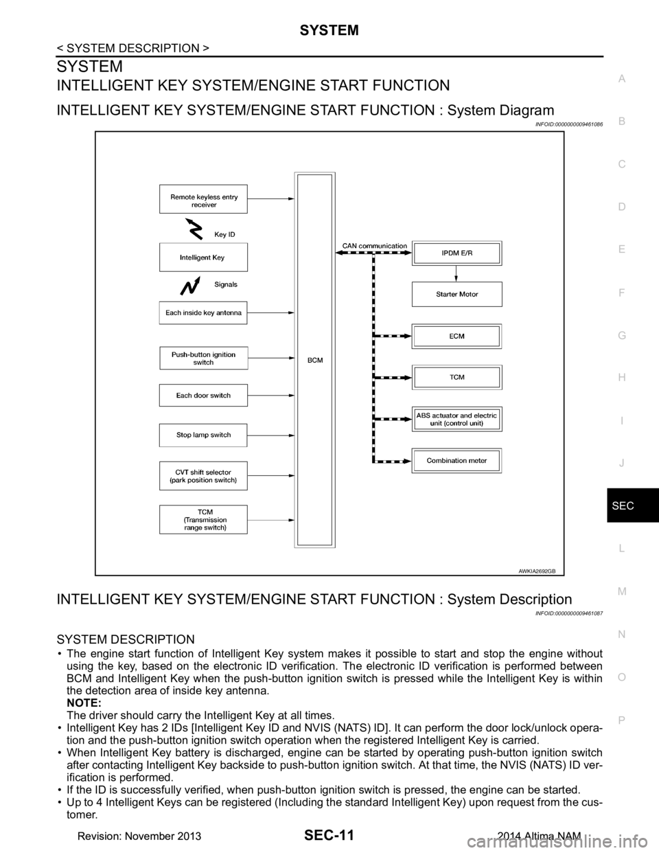
INTELLIGENT KEY SYSTEM/ ENGINE START FUNCTION
INTELLIGENT KEY SYSTEM/ENGINE ST ART FUNCTION : System Diagram
INFOID:0000000009461086
INTELLIGENT KEY SYSTEM/ENGINE STAR T FUNCTION : System Description
INFOID:0000000009461087
SYSTEM DESCRIPTION
• The engine start function of Intelligent Key system makes it possible to start and stop the engine without
using the key, based on the electronic ID verification. The electronic ID verification is performed between
BCM and Intelligent Key when the push-button ignition switch is pressed while the Intelligent Key is within
the detection area of inside key antenna.
NOTE:
The driver should carry the Intelligent Key at all times.
• Intelligent Key has 2 IDs [Intelligent Key ID and NVIS (NATS) ID]. It can perform the door lock/unlock opera-
tion and the push-button ignition switch operation when the registered Intelligent Key is carried.
• When Intelligent Key battery is discharged, engine c an be started by operating push-button ignition switch
after contacting Intelligent Key backside to push-button i gnition switch. At that time, the NVIS (NATS) ID ver-
ification is performed.
• If the ID is successfully verified, when push-button ignition switch is pressed, the engine can be started.
• Up to 4 Intelligent Keys can be registered (Includi ng the standard Intelligent Key) upon request from the cus-
tomer.
AWKIA2692GB
Revision: November 20132014 Altima NAMRevision: November 20132014 Altima NAM
Page 3837 of 4801
SEC-12
< SYSTEM DESCRIPTION >
SYSTEM
NOTE:
Refer to DLK-23, "INTELLIGENT KEY SYSTEM : System Description"
for any functions other than engine
start function of Intelligent Key system.
PRECAUTIONS FOR INTELLIGENT KEY SYSTEM
The transponder [the chip for NVIS (NATS) ID verifi cation] is integrated into the Intelligent Key.
In that case, the NVIS (NATS) ID verification can be performed when Intelligent Key backside is con-
tacted to push-button ignition switch. If verification result is OK, engine can be started.
OPERATION WHEN INTELLIGENT KEY IS CARRIED
1. When the push-button ignition switch is pressed, the BCM activates the inside key antenna and transmits
the request signal to the Intelligent Key.
2. The Intelligent Key receives the request signal and transmits the Intelligent Key ID signal to the BCM.
3. BCM receives the Intelligent Key ID signal via remote keyless entry receiver and verifies it with the regis-
tered ID.
4. BCM turns ACC relay ON and transmits the ignition power supply ON signal to IPDM E/R.
5. IPDM E/R turns the ignition relay ON and starts the ignition power supply.
6. BCM detects that the selector leve r position and brake pedal operating condition.
7. BCM transmits the starter request signal to IPDM E/R and turns the starter relay in IPDM E/R ON if BCM judges that the engine start condition* is satisfied.
8. IPDM E/R turns the starter control relay ON when receiving the starter request signal.
9. Power supply is supplied through the starter relay and the starter control relay to operate the starter motor. CAUTION:
If a malfunction is detected in the Intelligent Key system, the “KEY” warning lamp in the combina-
tion meter illuminates. At that ti me, the engine cannot be started.
10. When BCM receives feedback signal from ECM indicati ng that the engine is started, the BCM transmits a
stop signal to IPDM E/R and stops cranking by turning OFF the starter motor relay. (If engine start is
unsuccessful, cranking stops autom atically within 5 seconds.)
CAUTION:
When the Intelligent Key is carri ed outside of the vehicle (inside key antenna detection area) while
the power supply is in the ACC or ON position, even if the engine start condition* is satisfied, the
engine cannot be started.
*: For the engine start condition, refer to the tabl e below “POWER SUPPLY POSITION CHANGE TABLE BY
PUSH-BUTTON IGNITION SWITCH OPERATION”.
OPERATION RANGE
Engine can be started when Intelligent Key is inside the vehicle. However, sometimes engine may not start
when Intelligent Key is on instrument panel or in glove box.
ENGINE START OPERATION WHEN INTELLIGENT KEY IS CONTACTED TO PUSH-BUTTON IG-
NITION SWITCH
When Intelligent Key battery is discharged, the NVIS (NATS) ID verification between transponder in Intelligent
Key and BCM is performed when Intelligent Key backside is contacted to push-button ignition switch. If the
verification result is OK, engine can be started.
POWER SUPPLY POSITION CHANGE TABLE BY PUSH-BUTTON IGNITION SWITCH OPERA-
TION
The power supply position changing operation c an be performed with the following operations.
NOTE:
• When an Intelligent Key is within the detection area of inside key antenna and when Intelligent Key backside
is contacted to push-button ignition switch, it is equivalent to the operations below.
• When starting the engine, the BCM monitors under the engine start conditions:
- Brake pedal operating condition
- Selector lever position
- Vehicle speed
Vehicle speed: less than 4 km/h (2.5 MPH)
Revision: November 20132014 Altima NAMRevision: November 20132014 Altima NAM