2014 NISSAN TEANA stop start
[x] Cancel search: stop startPage 3159 of 4801
![NISSAN TEANA 2014 Service Manual
ENGINE OILLU-9
< PERIODIC MAINTENANCE > [QR25DE]
C
D E
F
G H
I
J
K L
M A
LU
NP
O
PERIODIC MAINTENANCE
ENGINE OIL
InspectionINFOID:0000000009461028
OIL LEVEL
• Before starting the engine, check the NISSAN TEANA 2014 Service Manual
ENGINE OILLU-9
< PERIODIC MAINTENANCE > [QR25DE]
C
D E
F
G H
I
J
K L
M A
LU
NP
O
PERIODIC MAINTENANCE
ENGINE OIL
InspectionINFOID:0000000009461028
OIL LEVEL
• Before starting the engine, check the](/manual-img/5/57390/w960_57390-3158.png)
ENGINE OILLU-9
< PERIODIC MAINTENANCE > [QR25DE]
C
D E
F
G H
I
J
K L
M A
LU
NP
O
PERIODIC MAINTENANCE
ENGINE OIL
InspectionINFOID:0000000009461028
OIL LEVEL
• Before starting the engine, check the oil level. If t
he engine is already started, stop it and allow 10 minutes
before checking.
• Check that the oil level is within the range (A) on the oil level
gauge.
• If it is out of range, add oil as necessary.
ENGINE OIL APPEARANCE
• Check engine oil for white milky appearance or excessive contamination.
• If engine oil becomes milky, it is highly probable t hat it is contaminated with engine coolant. Repair or
replace damaged parts.
OIL LEAKAGE
Check for oil leakage around the following areas:
•Oil pan
• Oil pan drain plug
• Oil pressure switch
• Oil filter
• Oil cooler
• Valve timing control cover and valve timing control solenoid valve
• Front cover
• Mating surface between cylinder block and cylinder head
• Mating surface between cylinder head and rocker cover
• Crankshaft oil seal (front and rear)
OIL PRESSURE CHECK
WARNING:
• Be careful not to burn yoursel f, as engine oil may be hot.
• Put the CVT shift selector in the Park "P" position.
1. Check engine oil level. Refer to OIL LEVEL.
2. Remove fender protector side cover (RH). Refer to EXT-26, "FENDER PROTECTOR : Exploded View"
.
3. Disconnect oil pressure switch harness connector at oil pressure switch. Remove oil pressure switch and install Tools.
CAUTION:
Do not drop or shock oil pressure switch.
4. Start engine and warm it up to normal operating temperature.
5. Check oil pressure with engine running under no-load, using Tool. NOTE:
JPBIA1497ZZ
Tool numbers : ST25051001 (J-25695-1)
: ST25052000 (J-25695-2)
WBIA0571E
Revision: November 20132014 Altima NAM
Page 3165 of 4801
![NISSAN TEANA 2014 Service Manual
OIL PUMPLU-15
< REMOVAL AND INSTALLATION > [QR25DE]
C
D E
F
G H
I
J
K L
M A
LU
NP
O
- Measure the inner diameter of inner rotor (1) with inside microme-
ter (A).
- (Clearance) = (Inner rotor inner NISSAN TEANA 2014 Service Manual
OIL PUMPLU-15
< REMOVAL AND INSTALLATION > [QR25DE]
C
D E
F
G H
I
J
K L
M A
LU
NP
O
- Measure the inner diameter of inner rotor (1) with inside microme-
ter (A).
- (Clearance) = (Inner rotor inner](/manual-img/5/57390/w960_57390-3164.png)
OIL PUMPLU-15
< REMOVAL AND INSTALLATION > [QR25DE]
C
D E
F
G H
I
J
K L
M A
LU
NP
O
- Measure the inner diameter of inner rotor (1) with inside microme-
ter (A).
- (Clearance) = (Inner rotor inner diameter) – (Oil pump inner rotor outer diameter)
• If measured/calculated values are out of the st andard, replace front cover and oil pump assembly.
REGULATOR VALVE TO OIL PUMP COVER CLEARANCE- (Clearance) = (Regulator valve hole (1) diameter) – (Regulator
valve (2) outer diameter)
• If the calculated value is out of the standard, replace front cover and oil pump assembly.
CAUTION:
• Coat regulator valve with engine oil.
• Make sure that it falls smoothly into valve hole by its own weight.
INSPECTION AFTER INSTALLATION
1. Check the engine oil level. Refer to LU-9, "Inspection".
2. Start the engine, and check that there is no leakage of engine oil.
3. Stop the engine and wait for 10 minutes.
4. Check the engine oil level and adjust the level. Refer to LU-9, "Inspection"
.
ALBIA0818ZZ
Standard : Refer to LU-18, "Oil Pump".
Standard : Refer to LU-18, "Oil Pump"
.
ALBIA0819ZZ
Revision: November 20132014 Altima NAM
Page 3167 of 4801
![NISSAN TEANA 2014 Service Manual
OIL COOLERLU-17
< REMOVAL AND INSTALLATION > [QR25DE]
C
D E
F
G H
I
J
K L
M A
LU
NP
O
• Tighten oil cooler bolts to
specification in numerical order.
• Do not reuse O-ring.
InspectionINFOID:000 NISSAN TEANA 2014 Service Manual
OIL COOLERLU-17
< REMOVAL AND INSTALLATION > [QR25DE]
C
D E
F
G H
I
J
K L
M A
LU
NP
O
• Tighten oil cooler bolts to
specification in numerical order.
• Do not reuse O-ring.
InspectionINFOID:000](/manual-img/5/57390/w960_57390-3166.png)
OIL COOLERLU-17
< REMOVAL AND INSTALLATION > [QR25DE]
C
D E
F
G H
I
J
K L
M A
LU
NP
O
• Tighten oil cooler bolts to
specification in numerical order.
• Do not reuse O-ring.
InspectionINFOID:0000000009461037
INSPECTION AFTER REMOVAL
Oil Cooler
Check oil cooler for cracks. Check oil cooler for cloggi ng by blowing through engine coolant inlet. If necessary,
replace oil cooler.
INSPECTION AFTER INSTALLATION
1. Check the engine oil level and the engine coolant level and add engine oil and engine coolant. Refer to LU-9, "Inspection"
and CO-11, "System Inspection".
2. Start the engine, and check that there is no leakage of engine oil or engine coolant.
3. Stop the engine and wait for 10 minutes.
4. Check the engine oil level and the engine coolant level again. Refer to LU-9, "Inspection"
and CO-11,
"System Inspection".
Revision: November 20132014 Altima NAM
Page 3175 of 4801
![NISSAN TEANA 2014 Service Manual
ENGINE OILLU-25
< PERIODIC MAINTENANCE > [VQ35DE]
C
D E
F
G H
I
J
K L
M A
LU
NP
O
PERIODIC MAINTENANCE
ENGINE OIL
InspectionINFOID:0000000009461048
OIL LEVEL
NOTE:
• Before starting the engine, c NISSAN TEANA 2014 Service Manual
ENGINE OILLU-25
< PERIODIC MAINTENANCE > [VQ35DE]
C
D E
F
G H
I
J
K L
M A
LU
NP
O
PERIODIC MAINTENANCE
ENGINE OIL
InspectionINFOID:0000000009461048
OIL LEVEL
NOTE:
• Before starting the engine, c](/manual-img/5/57390/w960_57390-3174.png)
ENGINE OILLU-25
< PERIODIC MAINTENANCE > [VQ35DE]
C
D E
F
G H
I
J
K L
M A
LU
NP
O
PERIODIC MAINTENANCE
ENGINE OIL
InspectionINFOID:0000000009461048
OIL LEVEL
NOTE:
• Before starting the engine, check the oil level. If the engine is already started, stop it and a llow 10 minutes before checking.
• Check that the oil level is within the range as indicated on the oil level gauge.
• If it is out of range, add oil as necessary.
ENGINE OIL APPEARANCE
• Check engine oil for white milky appearance or excessive contamination.
• If engine oil becomes milky, it is highly probable t hat it is contaminated with engine coolant. Repair or
replace damaged parts.
OIL LEAKAGE
Check for oil leakage around the following areas:
•Oil pan
• Oil pan drain plug
• Oil pressure switch
• Oil filter
• Oil cooler
• Intake valve timing control cover and intake valve timing control solenoid valve
• Front cover
• Mating surface between cylinder block and cylinder head
• Mating surface between cylinder head and rocker cover
• Crankshaft oil seal (front and rear)
OIL PRESSURE CHECK
WARNING:
• Be careful not to burn yoursel f, as engine oil may be hot.
• Put the CVT shift selector in the Park “P” position.
1. Check the oil level.
2. Remove fender protector side cover (RH). Refer to EXT-26, "FENDER PROTECTOR : Exploded View"
.
3. Disconnect oil pressure switch harness connector at the oil pressure switch. Remove oil pressure switch and install Tools.
CAUTION:
Do not drop or shock oil pressure switch.
4. Start the engine and warm it up to normal operating temperature.
5. Check oil pressure with engine running under no-load, using Tool. NOTE:
• When engine oil temperature is low, engine oil pressure becomes high.
JMA122D
Tool numbers : ST25051001 (J-25695-1)
: ST25052000 (J-25695-2)
WBIA0571E
Revision: November 20132014 Altima NAM
Page 3183 of 4801
![NISSAN TEANA 2014 Service Manual
OIL COOLERLU-33
< REMOVAL AND INSTALLATION > [VQ35DE]
C
D E
F
G H
I
J
K L
M A
LU
NP
O
When removing components such as hoses, tubes/lines, etc.
, cap or plug openings to prevent fluid from spill-
in NISSAN TEANA 2014 Service Manual
OIL COOLERLU-33
< REMOVAL AND INSTALLATION > [VQ35DE]
C
D E
F
G H
I
J
K L
M A
LU
NP
O
When removing components such as hoses, tubes/lines, etc.
, cap or plug openings to prevent fluid from spill-
in](/manual-img/5/57390/w960_57390-3182.png)
OIL COOLERLU-33
< REMOVAL AND INSTALLATION > [VQ35DE]
C
D E
F
G H
I
J
K L
M A
LU
NP
O
When removing components such as hoses, tubes/lines, etc.
, cap or plug openings to prevent fluid from spill-
ing.
REMOVAL
1. Remove the engine under cover. Refer to EXT-17, "Removal and Installation".
2. Remove the RH wheel and tire. Refer to WT-53, "Inspection"
.
3. Remove the front fender protector side cover RH. Refer to EXT-26, "FENDER PROTECTOR : Exploded
View".
4. Drain engine coolant. Refer to CO-36, "Changing Engine Coolant"
.
CAUTION:
Do not spill coolant on the drive belt.
5. Disconnect water hoses from oil cooler.
6. Remove the oil filter. Refer to LU-27, "Removal and Installation"
.
7. Remove oil cooler.
8. Remove core support cover. Refer to DLK-179, "Removal and Installation"
.
9. Remove front air duct. Refer to EM-84, "Removal and Installation"
.
10. Remove reservoir tank. Refer to CO-40, "Exploded View"
.
INSPECTION AFTER REMOVAL
1. Check oil cooler for cracks.
2. Check oil cooler for clogging by blowing through coolant inlet. If necessary, replace oil cooler.
Oil Pressure Relief Valve
Inspect oil pressure relief valve for movement, cracks and breaks by pushing the ball. If replacement is neces-
sary, remove valve by prying it out with a suitable tool. Install a new valve in place by tapping it.
INSTALLATION
Installation is in the reverse order of removal.
CAUTION:
• Do not reuse O-ring.
• Do not reuse copper gasket.
• When installing the oil cooler, align the oil cooler slot with the stopper of the oil pan.
INSPECTION AFTER INSTALLATION
1. Check the engine oil level and the engine coolant level and add engine oil and engine coolant. Refer to LU-9, "Inspection"
and CO-11, "System Inspection".
2. Start the engine, and check that there is no leakage of engine oil or engine coolant.
3. Stop the engine and wait for 10 minutes.
4. Check the engine oil level and the engine coolant level again. Refer to LU-9, "Inspection"
and CO-11,
"System Inspection".
Revision: November 20132014 Altima NAM
Page 3201 of 4801

ENGINE MAINTENANCE (QR25DE)MA-17
< PERIODIC MAINTENANCE >
C
D E
F
G H
I
J
K L
M B
MA
N
O A
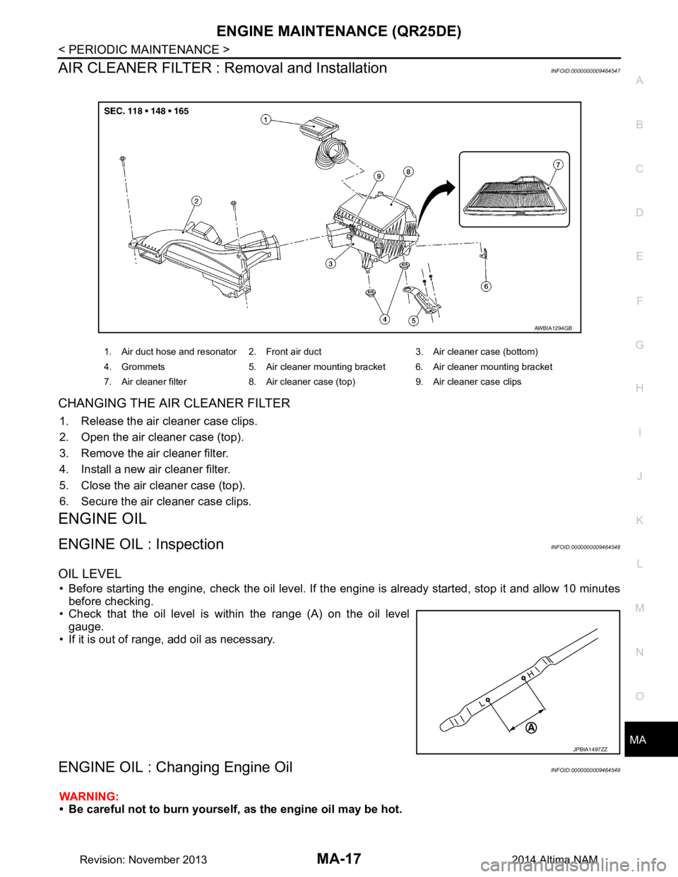
AIR CLEANER FILTER : Removal and InstallationINFOID:0000000009464547
CHANGING THE AIR CLEANER FILTER
1. Release the air cleaner case clips.
2. Open the air cleaner case (top).
3. Remove the air cleaner filter.
4. Install a new air cleaner filter.
5. Close the air cleaner case (top).
6. Secure the air cleaner case clips.
ENGINE OIL
ENGINE OIL : InspectionINFOID:0000000009464548
OIL LEVEL
• Before starting the engine, check the oil level. If t he engine is already started, stop it and allow 10 minutes
before checking.
• Check that the oil level is within the range (A) on the oil level gauge.
• If it is out of range, add oil as necessary.
ENGINE OIL : Changing Engine OilINFOID:0000000009464549
WARNING:
• Be careful not to burn yourself, as the engine oil may be hot.
1. Air duct hose and resonator 2. Front air duct 3. Air cleaner case (bottom)
4. Grommets 5. Air cleaner mounting bracket 6. Air cleaner mounting bracket
7. Air cleaner filter 8. Air cleaner case (top) 9. Air cleaner case clips
AWBIA1294GB
JPBIA1497ZZ
Revision: November 20132014 Altima NAM
Page 3211 of 4801

ENGINE MAINTENANCE (VQ35DE)MA-27
< PERIODIC MAINTENANCE >
C
D E
F
G H
I
J
K L
M B
MA
N
O A
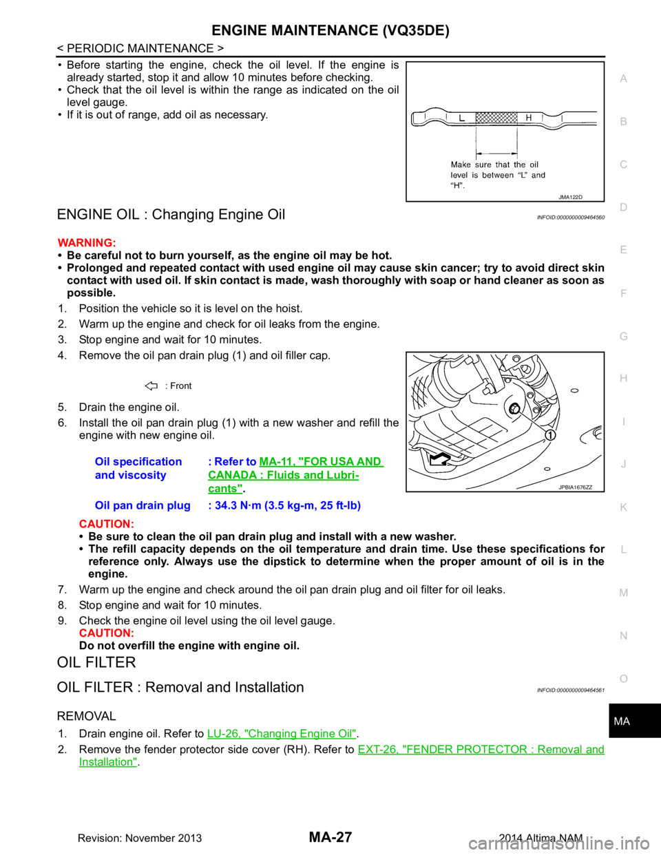
• Before starting the engine, check the oil level. If the engine is
already started, stop it and a llow 10 minutes before checking.
• Check that the oil level is within the range as indicated on the oil
level gauge.
• If it is out of range, add oil as necessary.
ENGINE OIL : Changing Engine OilINFOID:0000000009464560
WARNING:
• Be careful not to burn yourself, as the engine oil may be hot.
• Prolonged and repeated contact with used engine oil may cau se skin cancer; try to avoid direct skin
contact with used oil. If skin contact is made, w ash thoroughly with soap or hand cleaner as soon as
possible.
1. Position the vehicle so it is level on the hoist.
2. Warm up the engine and check for oil leaks from the engine.
3. Stop engine and wait for 10 minutes.
4. Remove the oil pan drain plug (1) and oil filler cap.
5. Drain the engine oil.
6. Install the oil pan drain plug (1) with a new washer and refill the engine with new engine oil.
CAUTION:
• Be sure to clean the oil pan drain plug and install with a new washer.
• The refill capacity depends on the oil temper ature and drain time. Use these specifications for
reference only. Always use the dipstick to determin e when the proper amount of oil is in the
engine.
7. Warm up the engine and check around the oil pan drain plug and oil filter for oil leaks.
8. Stop engine and wait for 10 minutes.
9. Check the engine oil level using the oil level gauge. CAUTION:
Do not overfill the en gine with engine oil.
OIL FILTER
OIL FILTER : Removal and InstallationINFOID:0000000009464561
REMOVAL
1. Drain engine oil. Refer to LU-26, "Changing Engine Oil".
2. Remove the fender protector side cover (RH). Refer to EXT-26, "FENDER PROTECTOR : Removal and
Installation".
JMA122D
: Front
Oil specification
and viscosity : Refer to
MA-11, "FOR USA AND
CANADA : Fluids and Lubri-
cants".
Oil pan drain plug : 34.3 N·m (3.5 kg-m, 25 ft-lb)JPBIA1676ZZ
Revision: November 20132014 Altima NAM
Page 3217 of 4801

CHASSIS AND BODY MAINTENANCEMA-33
< PERIODIC MAINTENANCE >
C
D E
F
G H
I
J
K L
M B
MA
N
O A
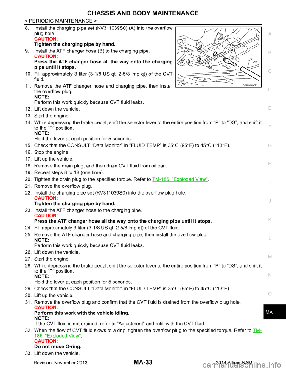
8. Install the charging pipe set (KV311039S0) (A) into the overflow
plug hole.
CAUTION:
Tighten the charging pipe by hand.
9. Install the ATF changer hose (B) to the charging pipe. CAUTION:
Press the ATF changer hose all the way onto the charging
pipe until it stops.
10. Fill approximately 3 liter (3-1/8 US qt, 2-5/8 lmp qt) of the CVT fluid.
11. Remove the ATF changer hose and charging pipe, then install the overflow plug.
NOTE:
Perform this work quickly because CVT fluid leaks.
12. Lift down the vehicle.
13. Start the engine.
14. While depressing the brake pedal, shift the selector leve r to the entire position from “P” to “DS”, and shift it
to the “P” position.
NOTE:
Hold the lever at each position for 5 seconds.
15. Check that the CONSULT “Data Monitor” in “FLUID TEMP” is 35°C (95 °F) to 45 °C (113 °F).
16. Stop the engine.
17. Lift up the vehicle.
18. Remove the drain plug, and then drain CVT fluid from oil pan.
19. Repeat steps 8 to 18 (one time).
20. Tighten the drain plug to the specified torque. Refer to TM-186, "Exploded View"
.
21. Remove the overflow plug.
22. Install the charging pipe set (KV311039S0) into the overflow plug hole. CAUTION:
Tighten the charging pipe by hand.
23. Install the ATF changer hose to the charging pipe. CAUTION:
Press the ATF changer hose all the way onto the charging pipe until it stops.
24. Fill approximately 3 liter (3-1/8 US qt, 2-5/8 lmp qt) of the CVT fluid.
25. Remove the ATF changer hose and charging pipe, then install the overflow plug. NOTE:
Perform this work quickly because CVT fluid leaks.
26. Lift down the vehicle.
27. Start the engine.
28. While depressing the brake pedal, shift the selector leve r to the entire position from “P” to “DS”, and shift it
to the “P” position.
NOTE:
Hold the lever at each position for 5 seconds.
29. Check that the CONSULT “Data Monitor” in “FLUID TEMP” is 35°C (95 °F) to 45 °C (113 °F).
30. Lift up the vehicle.
31. Remove the overflow plug and confirm that the CV T fluid is drained from the overflow plug hole.
CAUTION:
Perform this work with the vehicle idling.
NOTE:
If the CVT fluid is not drained, refer to “Adjustment” and refill with the CVT fluid.
32. When the flow of CVT fluid slows to a drip, tighten the overflow plug to the specified torque. Refer to TM-
186, "Exploded View".
CAUTION:
Do not reuse O-ring.
33. Lift down the vehicle.
JSDIA3713ZZ
Revision: November 20132014 Altima NAM