2014 NISSAN TEANA stop start
[x] Cancel search: stop startPage 4567 of 4801
![NISSAN TEANA 2014 Service Manual
TM-352
< DTC/CIRCUIT DIAGNOSIS >[CVT: RE0F10E]
P0965 PRESSURE CONTROL SOLENOID B
1.PREPARATION BEFORE WORK
If another "DTC CONFIRMATION PROCEDURE" occurs just before, turn ignition switch OFF and wa NISSAN TEANA 2014 Service Manual
TM-352
< DTC/CIRCUIT DIAGNOSIS >[CVT: RE0F10E]
P0965 PRESSURE CONTROL SOLENOID B
1.PREPARATION BEFORE WORK
If another "DTC CONFIRMATION PROCEDURE" occurs just before, turn ignition switch OFF and wa](/manual-img/5/57390/w960_57390-4566.png)
TM-352
< DTC/CIRCUIT DIAGNOSIS >[CVT: RE0F10E]
P0965 PRESSURE CONTROL SOLENOID B
1.PREPARATION BEFORE WORK
If another "DTC CONFIRMATION PROCEDURE" occurs just before, turn ignition switch OFF and wait for at
least 10 seconds, then perform the next test.
>> GO TO 2.
2.CHECK DTC DETECTION
1. Start the engine.
2. Drive the vehicle.
3. Maintain the following conditions for 20 seconds or more.
4. Stop the vehicle.
5. Check the first trip DTC.
Is
“P0965”detected?
YES >> Go to TM-352, "Diagnosis Procedure".
NO >> INSPECTION END
Diagnosis ProcedureINFOID:0000000009464309
1.CHECK INTERMITTENT INCIDENT
Refer to GI-43, "Intermittent Incident"
.
Is the inspection result normal?
YES >> Replace transaxle assembly. Refer to TM-407, "Removal and Installation".
NO >> Repair or replace malfunctioning parts.
Vehicle speed : 40 km/h (25 MPH) or more
Revision: November 20132014 Altima NAMRevision: November 20132014 Altima NAM
Page 4573 of 4801
![NISSAN TEANA 2014 Service Manual
TM-358
< DTC/CIRCUIT DIAGNOSIS >[CVT: RE0F10E]
P2765 INPUT SPEED SENSOR B
>> GO TO 2.
2.CHECK DTC DETECTION
1. Start the engine.
2. Drive the vehicle.
3. Maintain the following conditions for 10 se NISSAN TEANA 2014 Service Manual
TM-358
< DTC/CIRCUIT DIAGNOSIS >[CVT: RE0F10E]
P2765 INPUT SPEED SENSOR B
>> GO TO 2.
2.CHECK DTC DETECTION
1. Start the engine.
2. Drive the vehicle.
3. Maintain the following conditions for 10 se](/manual-img/5/57390/w960_57390-4572.png)
TM-358
< DTC/CIRCUIT DIAGNOSIS >[CVT: RE0F10E]
P2765 INPUT SPEED SENSOR B
>> GO TO 2.
2.CHECK DTC DETECTION
1. Start the engine.
2. Drive the vehicle.
3. Maintain the following conditions for 10 seconds or more.
4. Stop the vehicle.
5. Check the first trip DTC.
Is
“P2765” detected?
YES >> Go to TM-358, "Diagnosis Procedure".
NO >> INSPECTION END
Diagnosis ProcedureINFOID:0000000009464315
1.CHECK OUTPUT SPEED SENSOR POWER CIRCUIT
1. Turn ignition switch OFF.
2. Disconnect output speed sensor connector.
3. Turn ignition switch ON.
4. Check voltage between output speed sensor harness connector terminal and ground.
Is the inspection result normal?
YES >> GO TO 2.
NO >> GO TO 6.
2.CHECK OUTPUT SPEED SENSOR GROUND CIRCUIT
Check continuity between output speed sensor harness connector terminal and ground.
Is the inspection result normal?
YES >> GO TO 3.
NO >> Repair or replace malfunctioning parts.
3.CHECK CIRCUIT BETWEEN OUTPUT S PEED SENSOR AND TCM (PART 1)
1. Turn ignition switch OFF.
2. Disconnect TCM connector.
3. Check continuity between output speed sensor harness connector terminal and TCM harness connector
terminal.
Is the inspection result normal?
Selector lever : “D” position
Engine speed : 1,200 rpm or more
Vehicle speed : 55 km/h (34 MPH) or more
+ −Vo l ta g e
Output speed sensor
Connector Terminal F23 3 Ground 10 – 16 V
Output speed sensor —Continuity
Connector Terminal
F23 1 Ground Existed
Output speed sensor TCM Continuity
Connector Terminal Connector Terminal
F23 2 F16 34 Existed
Revision: November 20132014 Altima NAMRevision: November 20132014 Altima NAM
Page 4590 of 4801
![NISSAN TEANA 2014 Service Manual
CVT CONTROL SYSTEMTM-375
< SYMPTOM DIAGNOSIS > [CVT: RE0F10E]
C
EF
G H
I
J
K L
M A
B
TM
N
O P
Symptom Table 2
Symptom
Torque converter
Transmission range switch
Oil pump
Forward clutch
Reverse br NISSAN TEANA 2014 Service Manual
CVT CONTROL SYSTEMTM-375
< SYMPTOM DIAGNOSIS > [CVT: RE0F10E]
C
EF
G H
I
J
K L
M A
B
TM
N
O P
Symptom Table 2
Symptom
Torque converter
Transmission range switch
Oil pump
Forward clutch
Reverse br](/manual-img/5/57390/w960_57390-4589.png)
CVT CONTROL SYSTEMTM-375
< SYMPTOM DIAGNOSIS > [CVT: RE0F10E]
C
EF
G H
I
J
K L
M A
B
TM
N
O P
Symptom Table 2
Symptom
Torque converter
Transmission range switch
Oil pump
Forward clutch
Reverse brake
Planetary gear
Bearings
Parking mechanism
Stop lamp switch
Shift lock solenoid
CVT shift selector
TM-410
TM-407BR-13TM-369TM-378
Shift Shock
Large shock (N
→ D position) 2 1
Large shock (N → R position) 2 1
Shock is too large for lock-up. 1
Slips/Will
Not Engage Vehicle cannot be started from D
position. 312
Vehicle cannot be started from R
position. 41 2 3
Does not lock-up. 1 3 2
Does not hold lock-up condition. 1 3 2
Lock-up is not released. 1 2
With selector lever in D position,
acceleration is extremely poor. 13 2
With selector lever in R position,
acceleration is extremely poor. 142 3
Slips at lock-up. 1 2
Revision: November 20132014 Altima NAMRevision: November 20132014 Altima NAM
Page 4746 of 4801

DIAGNOSIS SYSTEM (BCM)WW-11
< SYSTEM DESCRIPTION >
C
D E
F
G H
I
J
K
M A
B
WW
N
O P
WIPER
WIPER : CONSULT Func tion (BCM - WIPER)INFOID:0000000009944152
CAUTION:
After disconnecting the CONSULT vehicle interface (VI) from the data link connector, the ignition must
be cycled OFF → ON (for at least 5 seconds) → OFF. If this step is not performed, the BCM may not go
to ”sleep mode”, potentiall y causing a discharged battery and a no-start condition.
DATA MONITOR
ACTIVE TEST
WORK SUPPORT
* : Initial setting RAP system RETAINED PWR
×
Signal buffer system SIGNAL BUFFER ×
TPMS AIR PRESSURE MONITOR ××××
System Sub System
Direct Diagnostic Mode
Ecu Identification
Self Diagnostic Result
Data Monitor
Active Test
Work support
Configuration
CAN Diag Support Mntr
Monitor Item [Unit] Description
PUSH SW [On/Off] Indicates condition of push-button ignition switch.
VEH SPEED 1 [km/h] Indicates vehicle speed signal received from ABS on CAN communication line.
FR WIPER HI [On/Off]
Indicates condition of wiper operation of combination switch.
FR WIPER LOW [On/Off]
FR WASHER SW [On/Off]
FR WIPER INT [On/Off]
FR WIPER STOP [On/Off] Indicates front wiper auto stop signal received from IPDM E/R on CAN communication
line.
INT VOLUME [1 − 7] Indicates condition of intermittent wiper operation of combination switch.
Test Item Description
FR WIPER This test is able to check front wiper operation [Hi/Lo/INT/Off].
Support Item Setting Description
WIPER SPEED SETTING On Front wiper intermittent time linked with vehicle speed and wiper dial position.
Off* Front wiper intermittent time linked with wiper dial position.
Revision: November 20132014 Altima NAMRevision: November 20132014 Altima NAM
Page 4749 of 4801

WW-14
< SYSTEM DESCRIPTION >
DIAGNOSIS SYSTEM (IPDM E/R)
APPLICATION ITEM
CONSULT performs the following functions via CAN communication with IPDM E/R.
ECU IDENTIFICATION
The IPDM E/R part number is displayed.
SELF DIAGNOSTIC RESULT
Refer to PCS-20, "DTC Index".
DATA MONITOR
Direct Diagnostic Mode Description
Ecu Identification The IPDM E/R part number is displayed.
Self Diagnostic Result The IPDM E/R self diagnostic results are displayed.
Data Monitor The IPDM E/R input/output data is displayed in real time.
Active Test The IPDM E/R activates outputs to test components.
CAN Diag Support Mntr The result of transmit/receive diagnosis of CAN communication is displayed.
Monitor Item [Unit] Main
Signals Description
MOTOR FAN REQ [%] ×Indicates cooling fan speed signal received from ECM on CAN communication
line
AC COMP REQ [On/Off] ×Indicates A/C compressor request signal received from ECM on CAN commu-
nication line
TAIL&CLR REQ [On/Off] ×Indicates position light request signal received from BCM on CAN communica-
tion line
HL LO REQ [On/Off] ×Indicates low beam request signal received from BCM on CAN communication
line
HL HI REQ [On/Off] ×Indicates high beam request signal received from BCM on CAN communication
line
FR FOG REQ [On/Off] ×Indicates front fog light request signal received from BCM on CAN communica-
tion line
FR WIP REQ [Stop/1LOW/Low/Hi] ×Indicates front wiper request signal received from BCM on CAN communication
line
WIP AUTO STOP [STOP P/ACT P] ×Indicates condition of front wiper auto stop signal
WIP PROT [Off/BLOCK] ×Indicates condition of front wiper fail-safe operation
IGN RLY1 -REQ [On/Off] Indicates ignition switch ON signal received from BCM on CAN communication
line
IGN RLY [On/Off] ×Indicates condition of ignition relay
PUSH SW [On/Off] Indicates condition of push-button ignition switch
INTER/NP SW [On/Off] Indicates condition of CVT shift position
ST RLY CONT [On/Off] Indicates starter relay status signal received from BCM on CAN communication
line
IHBT RLY -REQ [On/Off] Indicates starter control relay signal received from BCM on CAN communication
line
ST/INHI RLY [Off/ ST /INHI] Indicates condition of starter relay and starter control relay
DETENT SW [On/Off] Indicates condition of CVT shift selector (park position switch)
DTRL REQ [Off] Indicates daytime light request signal received from BCM on CAN communica-
tion line
HOOD SW [On/Off] Indicates condition of hood switch
THFT HRN REQ [On/Off] Indicates theft warning horn request signal received from BCM on CAN commu-
nication line
Revision: November 20132014 Altima NAMRevision: November 20132014 Altima NAM
Page 4769 of 4801

WW-34
< DTC/CIRCUIT DIAGNOSIS >
FRONT WIPER MOTOR LO CIRCUIT
FRONT WIPER MOTOR LO CIRCUIT
Component Function CheckINFOID:0000000009464614
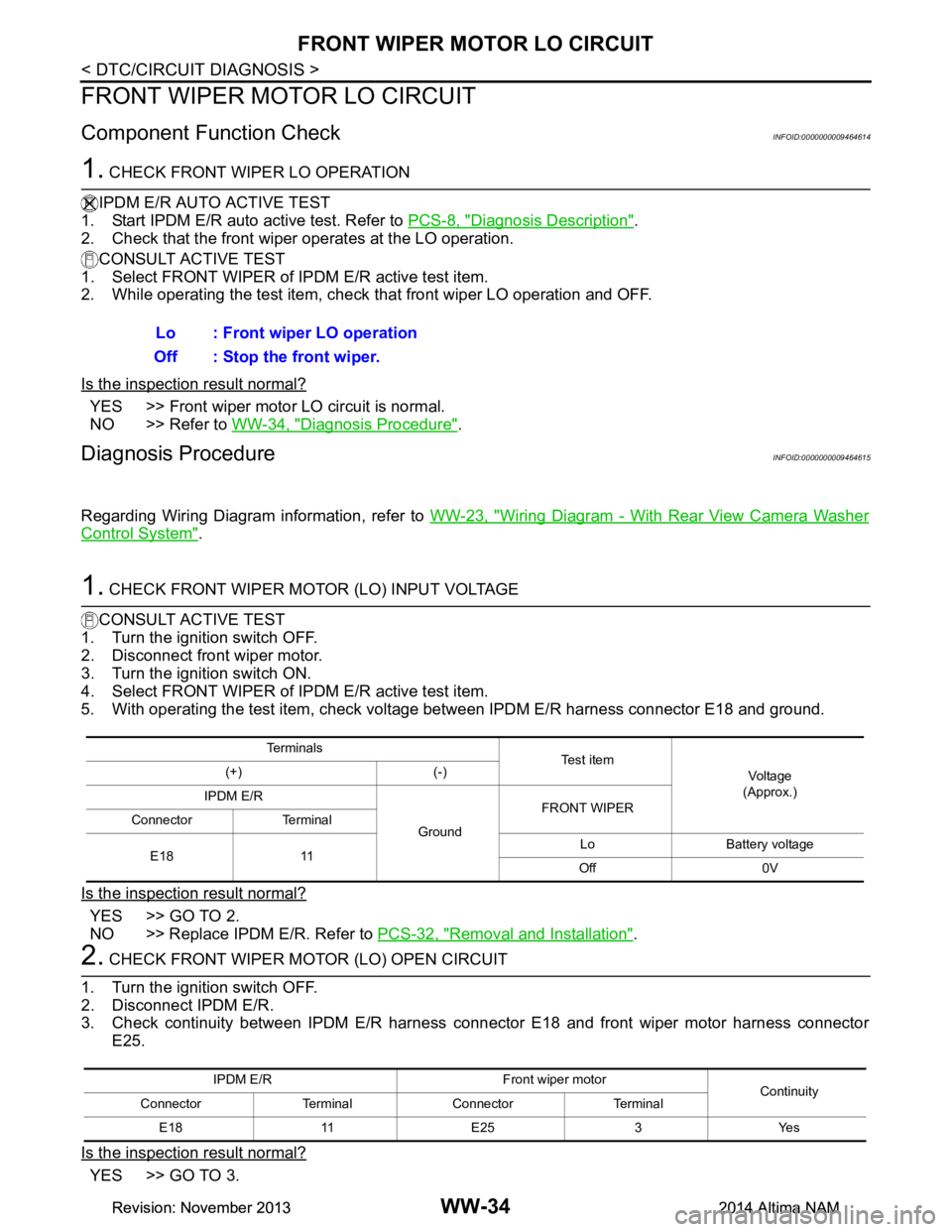
1. CHECK FRONT WIPER LO OPERATION
IPDM E/R AUTO ACTIVE TEST
1. Start IPDM E/R auto active test. Refer to PCS-8, "Diagnosis Description"
.
2. Check that the front wiper operates at the LO operation.
CONSULT ACTIVE TEST
1. Select FRONT WIPER of IPDM E/R active test item.
2. While operating the test item, check that front wiper LO operation and OFF.
Is the inspection result normal?
YES >> Front wiper motor LO circuit is normal.
NO >> Refer to WW-34, "Diagnosis Procedure"
.
Diagnosis ProcedureINFOID:0000000009464615
Regarding Wiring Diagram information, refer to WW-23, "Wiring Diagram - With Rear View Camera Washer
Control System".
1. CHECK FRONT WIPER MOTOR (LO) INPUT VOLTAGE
CONSULT ACTIVE TEST
1. Turn the ignition switch OFF.
2. Disconnect front wiper motor.
3. Turn the ignition switch ON.
4. Select FRONT WIPER of IPDM E/R active test item.
5. With operating the test item, check volt age between IPDM E/R harness connector E18 and ground.
Is the inspection result normal?
YES >> GO TO 2.
NO >> Replace IPDM E/R. Refer to PCS-32, "Removal and Installation"
.
2. CHECK FRONT WIPER MOTOR (LO) OPEN CIRCUIT
1. Turn the ignition switch OFF.
2. Disconnect IPDM E/R.
3. Check continuity between IPDM E/R harness c onnector E18 and front wiper motor harness connector
E25.
Is the inspection result normal?
YES >> GO TO 3. Lo : Front wiper LO operation
Off : Stop the front wiper.
Te r m i n a l s Te s t i t e m
Vo l ta g e
(Approx.)
(+) (-)
IPDM E/R
GroundFRONT WIPER
Connector Terminal
E18 11 Lo Battery voltage
Off 0V
IPDM E/R Front wiper motor Continuity
Connector Terminal Connector Terminal
E18 11 E25 3 Yes
Revision: November 20132014 Altima NAMRevision: November 20132014 Altima NAM
Page 4771 of 4801

WW-36
< DTC/CIRCUIT DIAGNOSIS >
FRONT WIPER MOTOR HI CIRCUIT
FRONT WIPER MOTOR HI CIRCUIT
Component Function CheckINFOID:0000000009464616
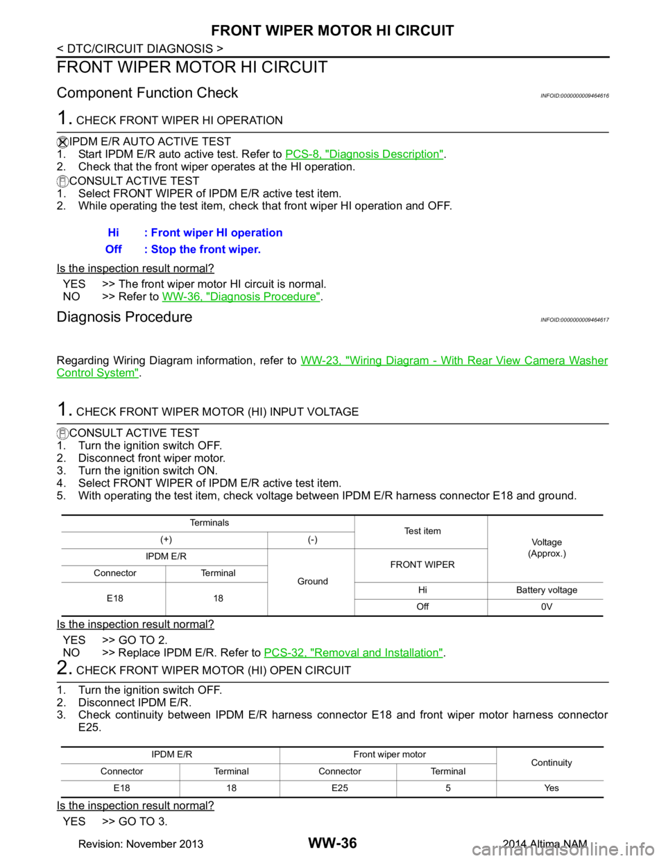
1. CHECK FRONT WIPER HI OPERATION
IPDM E/R AUTO ACTIVE TEST
1. Start IPDM E/R auto active test. Refer to PCS-8, "Diagnosis Description"
.
2. Check that the front wiper operates at the HI operation.
CONSULT ACTIVE TEST
1. Select FRONT WIPER of IPDM E/R active test item.
2. While operating the test item, check that front wiper HI operation and OFF.
Is the inspection result normal?
YES >> The front wiper motor HI circuit is normal.
NO >> Refer to WW-36, "Diagnosis Procedure"
.
Diagnosis ProcedureINFOID:0000000009464617
Regarding Wiring Diagram information, refer to WW-23, "Wiring Diagram - With Rear View Camera Washer
Control System".
1. CHECK FRONT WIPER MOTOR (HI) INPUT VOLTAGE
CONSULT ACTIVE TEST
1. Turn the ignition switch OFF.
2. Disconnect front wiper motor.
3. Turn the ignition switch ON.
4. Select FRONT WIPER of IPDM E/R active test item.
5. With operating the test item, check volt age between IPDM E/R harness connector E18 and ground.
Is the inspection result normal?
YES >> GO TO 2.
NO >> Replace IPDM E/R. Refer to PCS-32, "Removal and Installation"
.
2. CHECK FRONT WIPER MOTOR (HI) OPEN CIRCUIT
1. Turn the ignition switch OFF.
2. Disconnect IPDM E/R.
3. Check continuity between IPDM E/R harness c onnector E18 and front wiper motor harness connector
E25.
Is the inspection result normal?
YES >> GO TO 3. Hi : Front wiper HI operation
Off : Stop the front wiper.
Te r m i n a l s Te s t i t e m
Vo l ta g e
(Approx.)
(+) (-)
IPDM E/R
GroundFRONT WIPER
Connector Terminal
E18 18 Hi Battery voltage
Off 0V
IPDM E/R Fron t wiper motor
Continuity
Connector Terminal Connector Terminal
E18 18 E25 5 Yes
Revision: November 20132014 Altima NAMRevision: November 20132014 Altima NAM
Page 4783 of 4801

WW-48
< SYMPTOM DIAGNOSIS >
FRONT WIPER DOES NOT OPERATE
FRONT WIPER DOES NOT OPERATE
DescriptionINFOID:0000000009464625
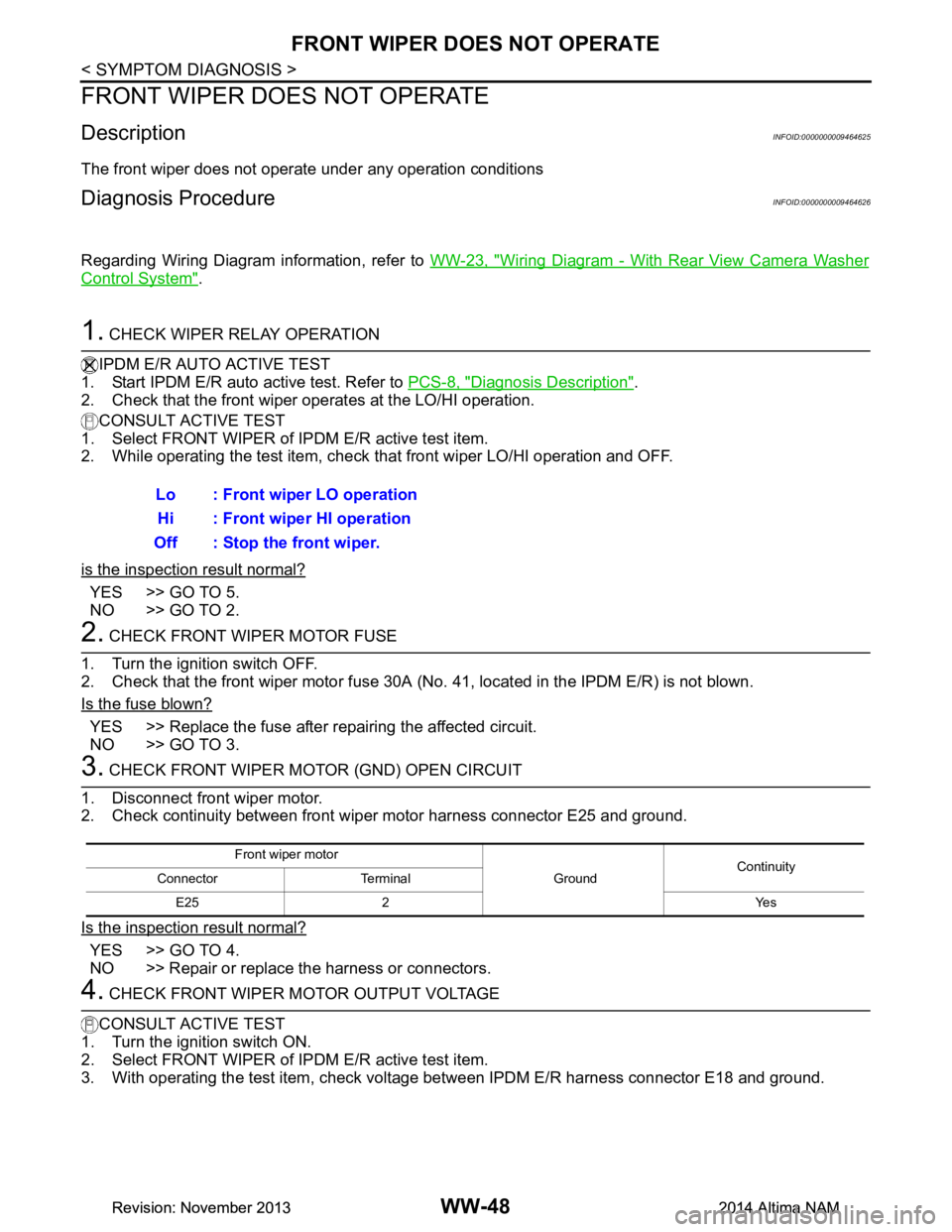
The front wiper does not operate under any operation conditions
Diagnosis ProcedureINFOID:0000000009464626
Regarding Wiring Diagram information, refer to WW-23, "Wiring Diagram - With Rear View Camera Washer
Control System".
1. CHECK WIPER RELAY OPERATION
IPDM E/R AUTO ACTIVE TEST
1. Start IPDM E/R auto active test. Refer to PCS-8, "Diagnosis Description"
.
2. Check that the front wiper operates at the LO/HI operation.
CONSULT ACTIVE TEST
1. Select FRONT WIPER of IPDM E/R active test item.
2. While operating the test item, check that front wiper LO/HI operation and OFF.
is the inspection result normal?
YES >> GO TO 5.
NO >> GO TO 2.
2. CHECK FRONT WIPER MOTOR FUSE
1. Turn the ignition switch OFF.
2. Check that the front wiper motor fuse 30A (No. 41, located in the IPDM E/R) is not blown.
Is the fuse blown?
YES >> Replace the fuse after repairing the affected circuit.
NO >> GO TO 3.
3. CHECK FRONT WIPER MOTOR (GND) OPEN CIRCUIT
1. Disconnect front wiper motor.
2. Check continuity between front wiper motor harness connector E25 and ground.
Is the inspection result normal?
YES >> GO TO 4.
NO >> Repair or replace the harness or connectors.
4. CHECK FRONT WIPER MOTOR OUTPUT VOLTAGE
CONSULT ACTIVE TEST
1. Turn the ignition switch ON.
2. Select FRONT WIPER of IPDM E/R active test item.
3. With operating the test item, check volt age between IPDM E/R harness connector E18 and ground.
Lo : Front wiper LO operation
Hi : Front wiper HI operation
Off : Stop the front wiper.
Front wiper motor
GroundContinuity
Connector Terminal
E25 2 Yes
Revision: November 20132014 Altima NAMRevision: November 20132014 Altima NAM