2014 NISSAN TEANA ignition
[x] Cancel search: ignitionPage 4160 of 4801

SYSTEMSTC-9
< SYSTEM DESCRIPTION >
C
D E
F
H I
J
K L
M A
B
STC
N
O P
HYDRAULIC PUMP ELECTRIC POWER STEE RING SYSTEM : Protection Function
INFOID:0000000009460346
• When the steering wheel is operated repeatedly or turned all the way for a long period during parking or low
speed driving, the function of the hydraulic pump elec tric power steering system becomes limited to prevent
the system from overheating. Cont inued operation of the steering wheel will cause the hydraulic pump elec-
tric power steering system to stop and the hydraulic pum p electric power steering system warning lamp may
come ON. In this case, the steering wheel operation temporarily becomes hard. This is not a malfunction.
When the engine is turned OFF (ignition switch OFF) and steering operation is stopped for a while, the tem-
perature of the hydraulic pump electric power steer ing system decreases and the steering operation returns
to normal after restarting the engine.
• Then, the hydraulic pump electric power steering syste m warning lamp turns OFF. If the system is OFF
under the protection state, the hydraulic pump electr ic power steering system warning lamp turns ON to
warn that the system is in the manual steering state. (This is not a system malfunction.) In addition, the fol-
lowing DTC remains to distinguish from malfunction.
C1608 Manual steering state
U1000 Normal control
NOTE:
If the cause is in a different ECU, the state changes to fixed steering assist force.
DTC Fail-safe condition
DTC vehicle condition
C160A The system temporarily enters the manual steering state. (This is not a hydraulic pump electric
power steering system malfunction.)
Revision: November 20132014 Altima NAMRevision: November 20132014 Altima NAM
Page 4161 of 4801

STC-10
< SYSTEM DESCRIPTION >
DIAGNOSIS SYSTEM (POWER STEERING CONTROL MODULE)
DIAGNOSIS SYSTEM (POWER STEERING CONTROL MODULE)
CONSULT FunctionINFOID:0000000009460347
CAUTION:
After disconnecting the CONSULT vehicle interface (VI) from the data link connector, the ignition must
be cycled OFF → ON (for at least 5 seconds) → OFF. If this step is not performed, the BCM may not go
to ”sleep mode”, potentially causing a di scharged battery and a no-start condition.
FUNCTION
CONSULT can display each diagnostic item using the diagnostic test modes shown as per the following.
ECU IDENTIFICATION
Displays the part number stored in the control unit.
SELF-DIAG RESULTS MODE
Refer to STC-13, "DTC Index".
When “CRNT” is displayed on self-diagnosis result.
• The system is presently malfunctioning.
When “PAST” is displayed on self-diagnosis result.• System malfunction in the past is detect ed, but the system is presently normal.
DATA MONITOR MODE
Diagnostic test mode Function
ECU identification The part number stored in the control unit can be read.
Self Diagnostic Results Self-diagnostic results and freeze frame data can be read and erased quickly.
Data monitor Input/Output data in the power steering control module can be read.
Monitor item (Unit) Remarks
BATTERY VOLT (V) Displays the power supply voltage for power steering control module.
STEERING ANGLE (deg) Displays the steering angle based on the steering angle signal transmitted by CAN com-
munications.
STR ANG SPD (deg/s) Displays the steering angle speed based on the steering angle signal transmitted by
CAN communications.
MOTOR CURRENT (A) Displays the cu rrent value consumed by power steering control module.
MTR REV SPD COMM (rpm) Displa ys the power steering motor speed command value.
MTR REV SPD (rpm) Displays the power steering motor speed.
C/U TEMP ( °C or °F) Displays the temperature of the power steering control module.
C/U TEMP A ( °C or °F) Displays the temperature of the power steering control module.
MTR ASSIST (%) Displays the current percentage of the allowable assist ratio power steering motor.
ESTM VHCL SPD (km/h or mph) Displays the vehicle speed calculated by the power steering control module.
WARNING LAMP (On/Off) Hydraulic pump electric power steering system warning lamp control status is displayed.
ENGINE STATUS (STOP/RUN/CRANK) Engine speed is displayed from engine condition signal with CAN communication
VHCL SPD JUDGE (OK/NG) Displays the receiving status of the vehicle speed signal transmitted by CAN communi-
cations.
Revision: November 20132014 Altima NAMRevision: November 20132014 Altima NAM
Page 4163 of 4801

STC-12
< ECU DIAGNOSIS INFORMATION >
POWER STEERING CONTROL MODULE
*4: This may not agree with the speedometer indication immediately after the ignition switch is turned ON. This
is not a malfunction.
TERMINAL LAYOUT
PHYSICAL VALUES
Fail-safeINFOID:0000000009460349
When an error occurs in the hydraulic pump electric pow er steering system, fail-safe brings the system to a
halt (manual steering) or restricted (constant steering assi st level) state. When the system is in a halt state,
fail-safe turns ON the hydraulic pump electric power steer ing warning lamp to warn the driver that the hydrau-
lic pump electric power steering system is in the manual steering state.
Protection FunctionINFOID:0000000009460350
• When the steering wheel is operated repeatedly or turned all the way for a long period during parking or low
speed driving, the function of the hydraulic pump elec tric power steering system becomes limited to prevent
the system from overheating. If the steering wheel is operated further more, the hydraulic pump electric
power steering system stops and the hydraulic pump el ectric power steering system warning lamp may be
turned ON. In this case, the steering wheel operation temporarily becomes hard. This is not a malfunction.
When the engine is turned OFF (ignition switch OFF) and steering operation is stopped for a while, the tem-
perature of the hydraulic pump electric power steeri ng system decreases and the steering operation returns
to normal after restarting the engine.
JSGIA0835ZZ
Te r m i n a l N o .
(Wire Color) Description
Condition Value
+ − Signal name Input/Output
1
(W) Ground Battery power supply Input Always Battery Voltage
2
(B) Ground Ground — Always 0 V
5
(BR) Ground Ignition power supply Input Ignition switch: ON Battery Voltage
Ignition switch: OFF 0 V
7
(P) — CAN-L Input/Output — —
8
(L) — CAN-H Input/Output — —
DTC Fail-safe condition
C1143 Certain steering assist force
C1601 Manual steering state
C1606 Manual steering state
C1607 Certain steering assist force
C1608 Manual steering state
U1000 Normal control
NOTE:
If the cause is in a different ECU, the state changes to fixed steering assist force.
Revision: November 20132014 Altima NAMRevision: November 20132014 Altima NAM
Page 4170 of 4801
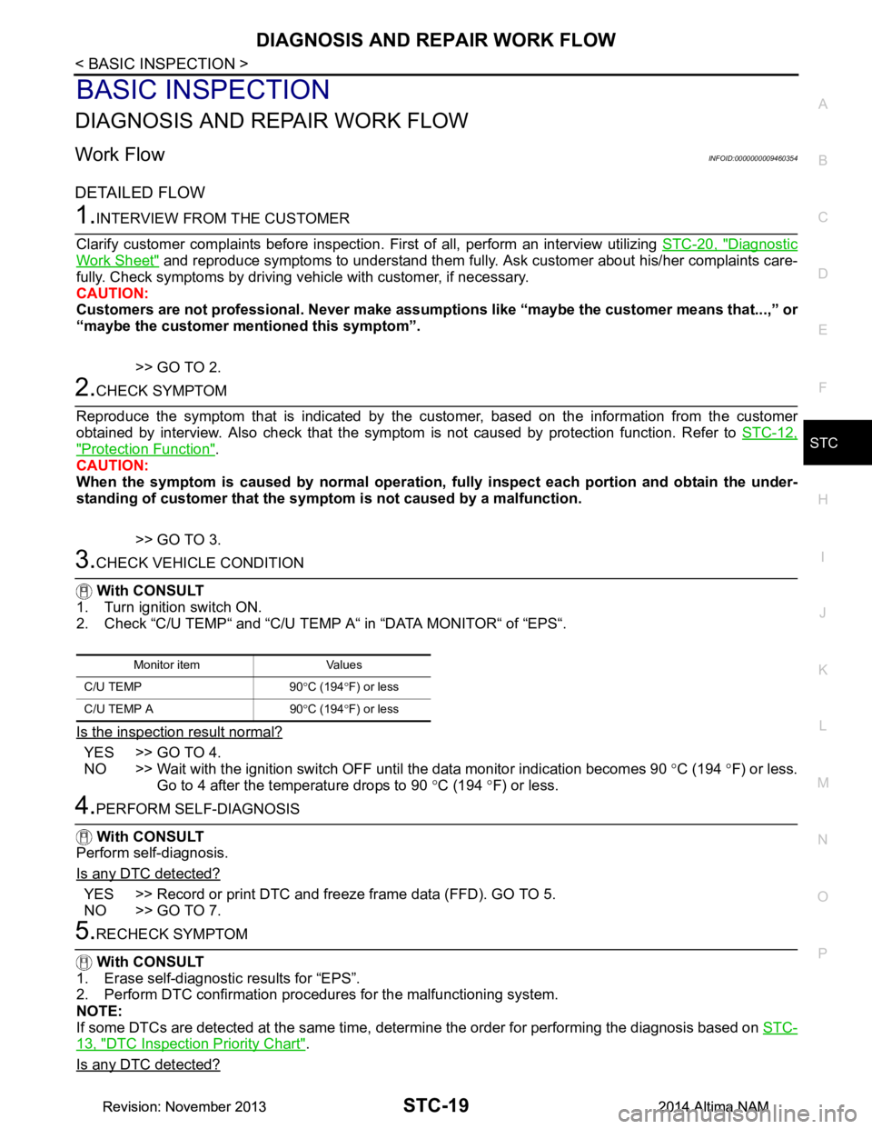
DIAGNOSIS AND REPAIR WORK FLOWSTC-19
< BASIC INSPECTION >
C
D E
F
H I
J
K L
M A
B
STC
N
O P
BASIC INSPECTION
DIAGNOSIS AND REPAIR WORK FLOW
Work FlowINFOID:0000000009460354
DETAILED FLOW
1.INTERVIEW FROM THE CUSTOMER
Clarify customer complaints before inspection. First of all, perform an interview utilizing STC-20, "Diagnostic
Work Sheet" and reproduce symptoms to understand them fully. A sk customer about his/her complaints care-
fully. Check symptoms by driving v ehicle with customer, if necessary.
CAUTION:
Customers are not professional. Never make assumpti ons like “maybe the customer means that...,” or
“maybe the customer mentioned this symptom”.
>> GO TO 2.
2.CHECK SYMPTOM
Reproduce the symptom that is indicated by the cu stomer, based on the information from the customer
obtained by interview. Also check that the symptom is not caused by protection function. Refer to STC-12,
"Protection Function".
CAUTION:
When the symptom is caused by normal operation, fully inspect each portion and obtain the under-
standing of customer that the symptom is not caused by a malfunction.
>> GO TO 3.
3.CHECK VEHICLE CONDITION
With CONSULT
1. Turn ignition switch ON.
2. Check “C/U TEMP“ and “C/U TEMP A“ in “DATA MONITOR“ of “EPS“.
Is the inspection result normal?
YES >> GO TO 4.
NO >> Wait with the ignition switch OFF until the data monitor indication becomes 90 °C (194 °F) or less.
Go to 4 after the temperature drops to 90 °C (194 °F) or less.
4.PERFORM SELF-DIAGNOSIS
With CONSULT
Perform self-diagnosis.
Is any DTC detected?
YES >> Record or print DTC and freeze frame data (FFD). GO TO 5.
NO >> GO TO 7.
5.RECHECK SYMPTOM
With CONSULT
1. Erase self-diagnostic results for “EPS”.
2. Perform DTC confirmation procedures for the malfunctioning system.
NOTE:
If some DTCs are detected at the same time, determine the order for performing the diagnosis based on STC-
13, "DTC Inspection Priority Chart".
Is any DTC detected?
Monitor item Values
C/U TEMP 90 °C (194 °F) or less
C/U TEMP A 90 °C (194 °F) or less
Revision: November 20132014 Altima NAMRevision: November 20132014 Altima NAM
Page 4173 of 4801
STC-22
< DTC/CIRCUIT DIAGNOSIS >
C1143 STEERING ANGLE SENSOR
DTC/CIRCUIT DIAGNOSIS
C1143 STEERING ANGLE SENSOR
DTC LogicINFOID:0000000009460356
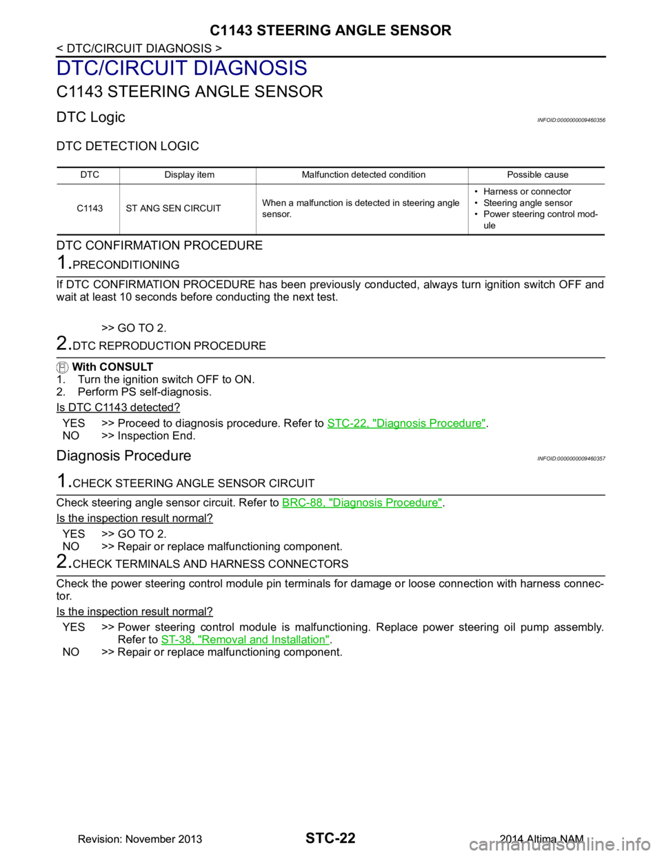
DTC DETECTION LOGIC
DTC CONFIRMATION PROCEDURE
1.PRECONDITIONING
If DTC CONFIRMATION PROCEDURE has been previously conducted, always turn ignition switch OFF and
wait at least 10 seconds before conducting the next test.
>> GO TO 2.
2.DTC REPRODUCTION PROCEDURE
With CONSULT
1. Turn the ignition switch OFF to ON.
2. Perform PS self-diagnosis.
Is DTC C1143 detected?
YES >> Proceed to diagnosis procedure. Refer to STC-22, "Diagnosis Procedure".
NO >> Inspection End.
Diagnosis ProcedureINFOID:0000000009460357
1.CHECK STEERING ANGLE SENSOR CIRCUIT
Check steering angle sensor circuit. Refer to BRC-88, "Diagnosis Procedure"
.
Is the inspection result normal?
YES >> GO TO 2.
NO >> Repair or replace malfunctioning component.
2.CHECK TERMINALS AND HARNESS CONNECTORS
Check the power steering control module pin termi nals for damage or loose connection with harness connec-
tor.
Is the inspection result normal?
YES >> Power steering control module is malfunctioni ng. Replace power steering oil pump assembly.
Refer to ST-38, "Removal and Installation"
.
NO >> Repair or replace malfunctioning component.
DTC Display item Malfunction detected condition Possible cause
C1143 ST ANG SEN CIRCUIT When a malfunction is detected in steering angle
sensor. • Harness or connector
• Steering angle sensor
• Power steering control mod-
ule
Revision: November 20132014 Altima NAMRevision: November 20132014 Altima NAM
Page 4174 of 4801
C1601 BATTERY POWER SUPPLYSTC-23
< DTC/CIRCUIT DIAGNOSIS >
C
D E
F
H I
J
K L
M A
B
STC
N
O P
C1601 BATTERY POWER SUPPLY
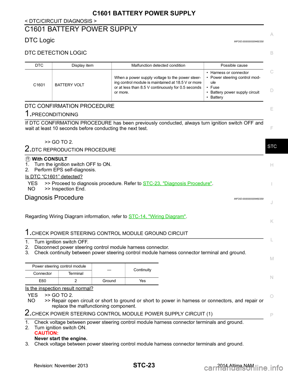
DTC LogicINFOID:0000000009460358
DTC DETECTION LOGIC
DTC CONFIRMATION PROCEDURE
1.PRECONDITIONING
If DTC CONFIRMATION PROCEDURE has been previously conducted, always turn ignition switch OFF and
wait at least 10 seconds before conducting the next test.
>> GO TO 2.
2.DTC REPRODUCTION PROCEDURE
With CONSULT
1. Turn the ignition switch OFF to ON.
2. Perform EPS self-diagnosis.
Is DTC
“C1601” detected?
YES >> Proceed to diagnosis procedure. Refer to STC-23, "Diagnosis Procedure".
NO >> Inspection End.
Diagnosis ProcedureINFOID:0000000009460359
Regarding Wiring Diagram information, refer to STC-14, "Wiring Diagram".
1.CHECK POWER STEERING CONTROL MODULE GROUND CIRCUIT
1. Turn ignition switch OFF.
2. Disconnect power steering control module harness connector.
3. Check continuity between power steering control module harness connector terminal and ground.
Is the inspection result normal?
YES >> GO TO 2.
NO >> Repair open circuit or short to ground or short to power in harness or connectors, and repair or
replace the malfunctioning component.
2.CHECK POWER STEERING CONTROL MO DULE POWER SUPPLY CIRCUIT (1)
1. Check voltage between power steering control module harness connector terminals and ground.
2. Turn ignition switch ON. CAUTION:
Never start the engine.
3. Check voltage between power steering control module harness connector terminals and ground.
DTC Display item Malfunction detected condition Possible cause
C1601 BATTERY VOLT When a power supply voltage to the power steer-
ing control module is maintained at 18.5 V or more
or at less than 8.5 V continuously for 0.5 seconds
or more. • Harness or connector
• Power steering control mod-
ule
•Fuse
• Battery power supply circuit
•Battery
Power steering control module
—Continuity
Connector Terminal
E60 2 Ground Yes
Revision: November 20132014 Altima NAMRevision: November 20132014 Altima NAM
Page 4175 of 4801
STC-24
< DTC/CIRCUIT DIAGNOSIS >
C1601 BATTERY POWER SUPPLY
Is the inspection result normal?
YES >> GO TO 4.
NO >> GO TO 3.
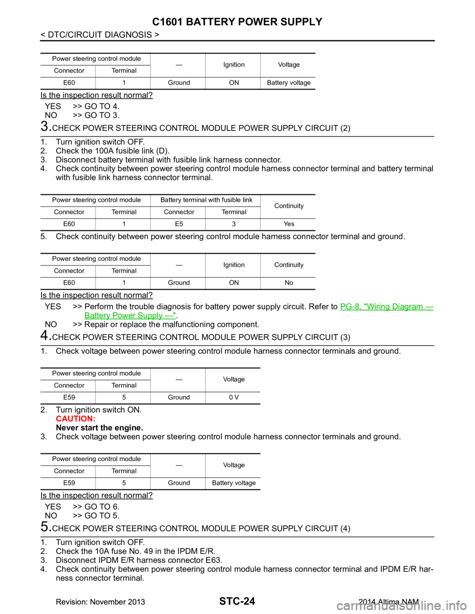
3.CHECK POWER STEERING CONTROL MODULE POWER SUPPLY CIRCUIT (2)
1. Turn ignition switch OFF.
2. Check the 100A fusible link (D).
3. Disconnect battery terminal with fusible link harness connector.
4. Check continuity between power steering contro l module harness connector terminal and battery terminal
with fusible link harness connector terminal.
5. Check continuity between power steering c ontrol module harness connector terminal and ground.
Is the inspection result normal?
YES >> Perform the trouble diagnosis for battery power supply circuit. Refer to PG-8, "Wiring Diagram —
Battery Power Supply —".
NO >> Repair or replace the malfunctioning component.
4.CHECK POWER STEERING CONTROL MODULE POWER SUPPLY CIRCUIT (3)
1. Check voltage between power steering control module harness connector terminals and ground.
2. Turn ignition switch ON. CAUTION:
Never start the engine.
3. Check voltage between power steering control module harness connector terminals and ground.
Is the inspection result normal?
YES >> GO TO 6.
NO >> GO TO 5.
5.CHECK POWER STEERING CONTROL MODULE POWER SUPPLY CIRCUIT (4)
1. Turn ignition switch OFF.
2. Check the 10A fuse No. 49 in the IPDM E/R.
3. Disconnect IPDM E/R harness connector E63.
4. Check continuity between power steering control module harness connector terminal and IPDM E/R har-
ness connector terminal.
Power steering control module — Ignition Voltage
Connector Terminal
E60 1 Ground ON Battery voltage
Power steering control module Batte ry terminal with fusible link
Continuity
Connector Terminal Connector Terminal
E60 1 E5 3 Yes
Power steering control module — Ignition Continuity
Connector Terminal
E60 1 Ground ON No
Power steering control module —Voltage
Connector Terminal
E59 5 Ground 0 V
Power steering control module —Voltage
Connector Terminal
E59 5 Ground Battery voltage
Revision: November 20132014 Altima NAMRevision: November 20132014 Altima NAM
Page 4176 of 4801
C1601 BATTERY POWER SUPPLYSTC-25
< DTC/CIRCUIT DIAGNOSIS >
C
D E
F
H I
J
K L
M A
B
STC
N
O P
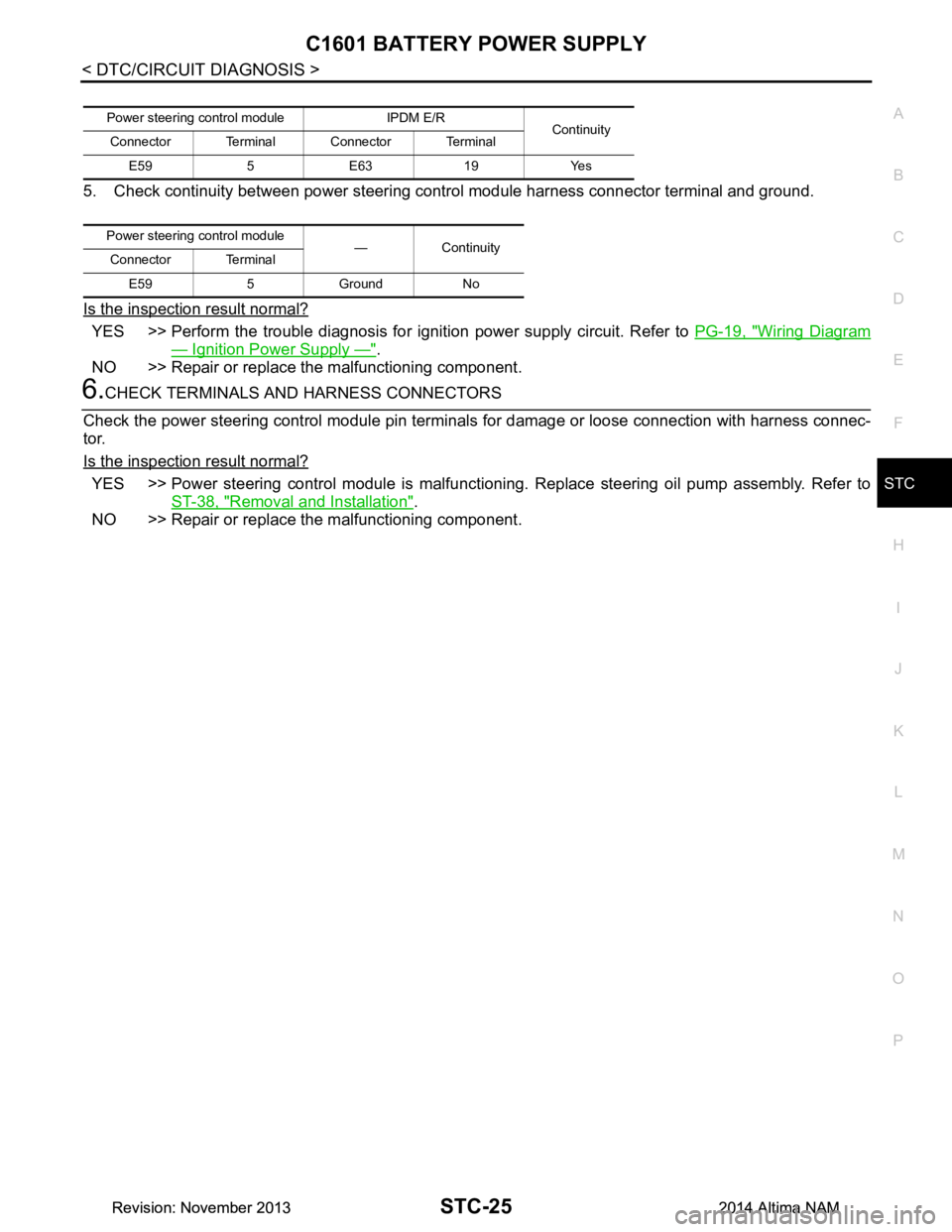
5. Check continuity between power steering control module harness connector terminal and ground.
Is the inspection result normal?
YES >> Perform the trouble diagnosis for i gnition power supply circuit. Refer to PG-19, "Wiring Diagram
— Ignition Power Supply —".
NO >> Repair or replace the malfunctioning component.
6.CHECK TERMINALS AND HARNESS CONNECTORS
Check the power steering control module pin terminal s for damage or loose connection with harness connec-
tor.
Is the inspection result normal?
YES >> Power steering control module is malfunctioni ng. Replace steering oil pump assembly. Refer to
ST-38, "Removal and Installation"
.
NO >> Repair or replace the malfunctioning component.
Power steering cont rol module IPDM E/R
Continuity
Connector Terminal Connector Terminal
E59 5 E63 19 Yes
Power steering control module
—Continuity
Connector Terminal
E59 5 Ground No
Revision: November 20132014 Altima NAMRevision: November 20132014 Altima NAM