2014 NISSAN TEANA ignition
[x] Cancel search: ignitionPage 4188 of 4801
UNBALANCE STEERING WHEEL TURNING FORCE (TORQUE VARIATION)
STC-37
< SYMPTOM DIAGNOSIS >
C
D E
F
H I
J
K L
M A
B
STC
N
O P
UNBALANCE STEERING WHEEL TU RNING FORCE (TORQUE VARIA-
TION)
Diagnosis ProcedureINFOID:0000000009460378
1.PERFORM SELF-DIAGNOSIS
With CONSULT
Perform “EPS” self-diagnosis.
Is a malfunctioning system displayed?
YES >> Check malfunctioning system. Refer to STC-13, "DTC Index".
NO >> GO TO 2.
2.CHECK THE POWER STEERING CONTROL MODULE SIGNAL (1)
With CONSULT
1. Start the engine. CAUTION:
Never drive the vehicle.
2. Turn the steering wheel until it stops.
3. Select “MTR ASSIST” in “DATA MONITOR” of “EPS”.
Is the display value
“100%”?
YES >> GO TO 4.
NO >> GO TO 3.
3.CHECK THE POWER STEERING CONTROL MODULE SIGNAL (2)
With CONSULT
1. Select “C/U TEMP” and “C/U TEMP A” in “DATA MONITOR” of “EPS”.
2. Stop the system until the DATA MONITOR display value drops to “90 °C (194 °F)” or less.
3. Check whether symptom continues.
Did symptom continue?
YES >> GO TO 4.
NO >> This occurs because the protection function lowers the assist force. It is not a system malfunction.
Inspection End.
4.CHECK THE POWER STEERING CONTROL MODULE SIGNAL (3)
With CONSULT
1. Turn the steering wheel to the straight -ahead position. (There is no steering force.)
2. Select “BATTERY VOLT” in “DATA MONITOR” of “EPS”.
Is the display value
“10.5 V” or more?
YES >> GO TO 5.
NO >> Check the battery power system. Refer to STC-23, "Diagnosis Procedure"
.
5.CHECK THE POWER STEERING CONTROL MODULE SIGNAL (4)
With CONSULT
Select in “ESTM VHCL SPD” in “DATA MONITOR” of “EPS”.
*: This may not agree with the speedometer indication immediately after the ignition switch is turned ON. This
is not a malfunction.
Is the check result normal?
YES >> GO TO 6.
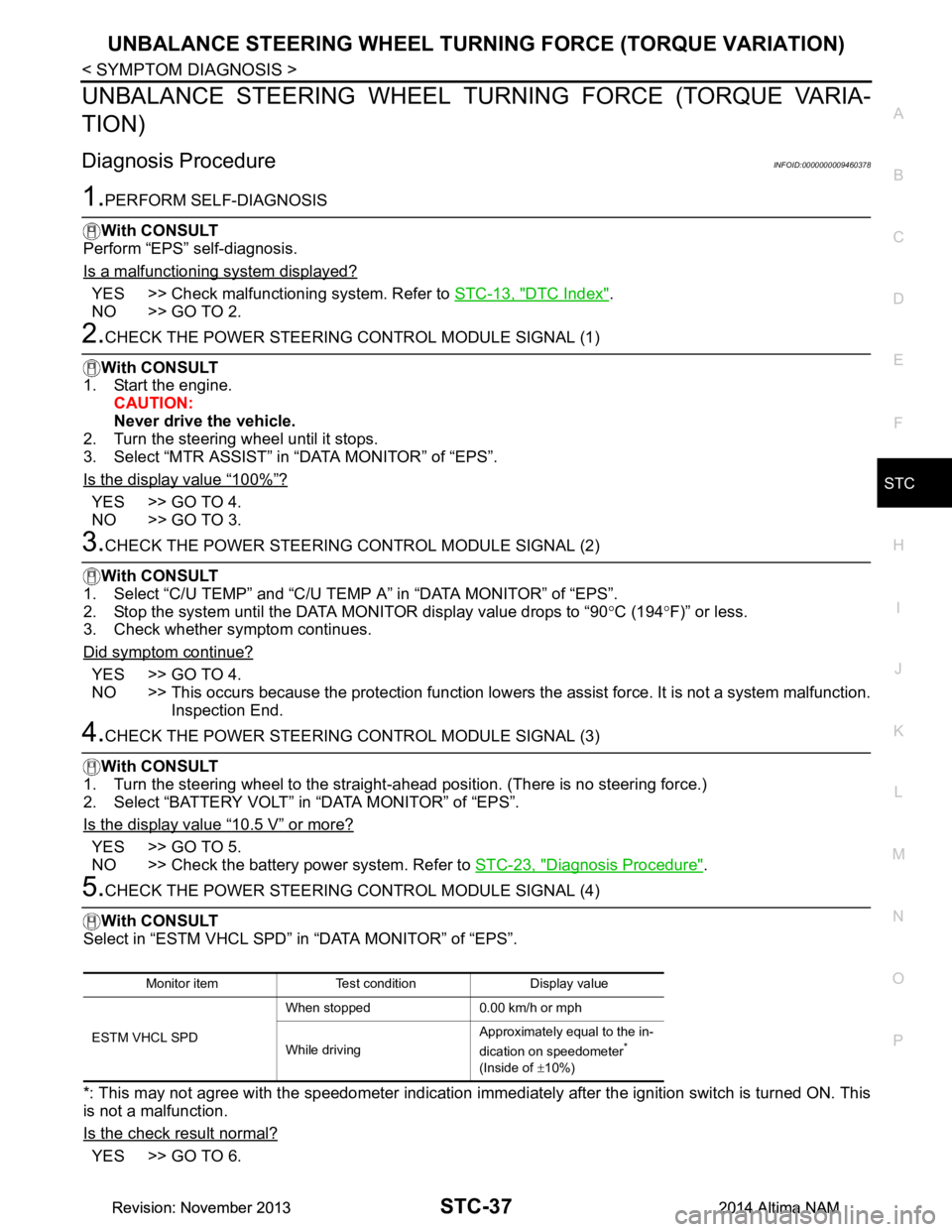
Monitor item Test condition Display value
ESTM VHCL SPD When stopped 0.00 km/h or mph
While driving Approximately equal to the in-
dication on speedometer
*
(Inside of ±10%)
Revision: November 20132014 Altima NAMRevision: November 20132014 Altima NAM
Page 4192 of 4801
STR-2
< PRECAUTION >
PRECAUTIONS
PRECAUTION
PRECAUTIONS
Precaution for Supplemental Restraint System (SRS) "AIR BAG" and "SEAT BELT
PRE-TENSIONER"
INFOID:0000000009951694
The Supplemental Restraint System such as “A IR BAG” and “SEAT BELT PRE-TENSIONER”, used along
with a front seat belt, helps to reduce the risk or severi ty of injury to the driver and front passenger for certain
types of collision. Information necessary to service the system safely is included in the SR and SB section of
this Service Manual.
WARNING:
• To avoid rendering the SRS inopera tive, which could increase the risk of personal injury or death in
the event of a collision which would result in air bag inflation, all maintenance must be performed by
an authorized NISS AN/INFINITI dealer.
• Improper maintenance, including in correct removal and installation of the SRS, can lead to personal
injury caused by unintent ional activation of the system. For re moval of Spiral Cable and Air Bag
Module, see the SR section.
• Do not use electrical test equipmen t on any circuit related to the SRS unless instructed to in this
Service Manual. SRS wiring harn esses can be identified by yellow and/or orange harnesses or har-
ness connectors.
PRECAUTIONS WHEN USING POWER TOOLS (AIR OR ELECTRIC) AND HAMMERS
WARNING:
• When working near the Airbag Diagnosis Sensor Unit or other Airbag System sensors with the Igni-
tion ON or engine running, DO NOT use air or electri c power tools or strike near the sensor(s) with a
hammer. Heavy vibration could activate the sensor( s) and deploy the air bag(s), possibly causing
serious injury.
• When using air or electric power tools or hammers , always switch the Ignition OFF, disconnect the
battery and wait at least three minutes before performing any service.
Revision: November 20132014 Altima NAMRevision: November 20132014 Altima NAM
Page 4194 of 4801
STR-4
< SYSTEM DESCRIPTION >
COMPONENT PARTS
SYSTEM DESCRIPTION
COMPONENT PARTS
QR25DE
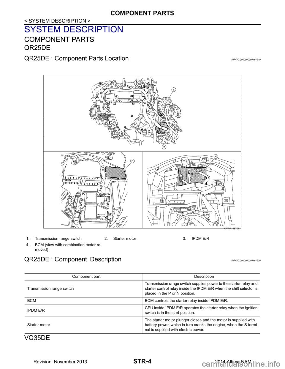
QR25DE : Component Parts LocationINFOID:0000000009461219
QR25DE : Component DescriptionINFOID:0000000009461220
VQ35DE
1. Transmission range switch 2. Starter motor 3. IPDM E/R
4. BCM (view with combination meter re- moved)
AWBIA1287ZZ
Component part Description
Transmission range switch Transmission range switch supplies power to the starter relay and
starter control relay inside the IPDM E/R when the shift selector is
placed in the P or N position.
BCM BCM controls the starter relay inside IPDM E/R.
IPDM E/R CPU inside IPDM E/R operates the starter relay when the ignition
switch is in the start position.
Starter motor The starter motor plunger closes and the motor is supplied with
battery power, which in turn cranks the engine, when the S termi-
nal is supplied with electric power.
Revision: November 20132014 Altima NAMRevision: November 20132014 Altima NAM
Page 4195 of 4801
COMPONENT PARTSSTR-5
< SYSTEM DESCRIPTION >
C
D E
F
G H
I
J
K L
M A
STR
NP
O
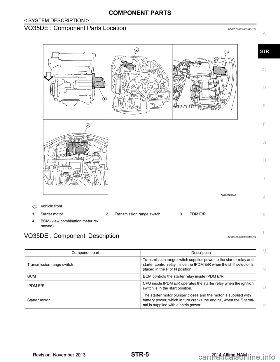
VQ35DE : Component Parts LocationINFOID:0000000009461221
VQ35DE : Component DescriptionINFOID:0000000009461222
Vehicle front
1. Starter motor 2. Transmission range switch 3. IPDM E/R
4. BCM (view combination meter re- moved)
AWBIA1288ZZ
Component part Description
Transmission range switch Transmission range switch supplies power to the starter relay and
starter control relay inside the IPDM E/R when the shift selector is
placed in the P or N position.
BCM BCM controls the starter relay inside IPDM E/R.
IPDM E/R CPU inside IPDM E/R operates the starter relay when the ignition
switch is in the start position.
Starter motor The starter motor plunger closes and the motor is supplied with
battery power, which in turn cranks the engine, when the S termi-
nal is supplied with electric power.
Revision: November 20132014 Altima NAMRevision: November 20132014 Altima NAM
Page 4208 of 4801
STR-18
< DTC/CIRCUIT DIAGNOSIS >
B TERMINAL CIRCUIT
DTC/CIRCUIT DIAGNOSIS
B TERMINAL CIRCUIT
DescriptionINFOID:0000000009461229
Terminal “B” is constantly supplied with battery power.
Diagnosis ProcedureINFOID:0000000009461230
Regarding Wiring Diagram information, refer to STR-7, "Wiring Diagram".
CAUTION:
Perform diagnosis under the condi tion that the engine cannot start by the following procedure.
1. Remove fuel pump fuse.
2. Crank or start the engine (where possi ble) until the fuel pressure is released.
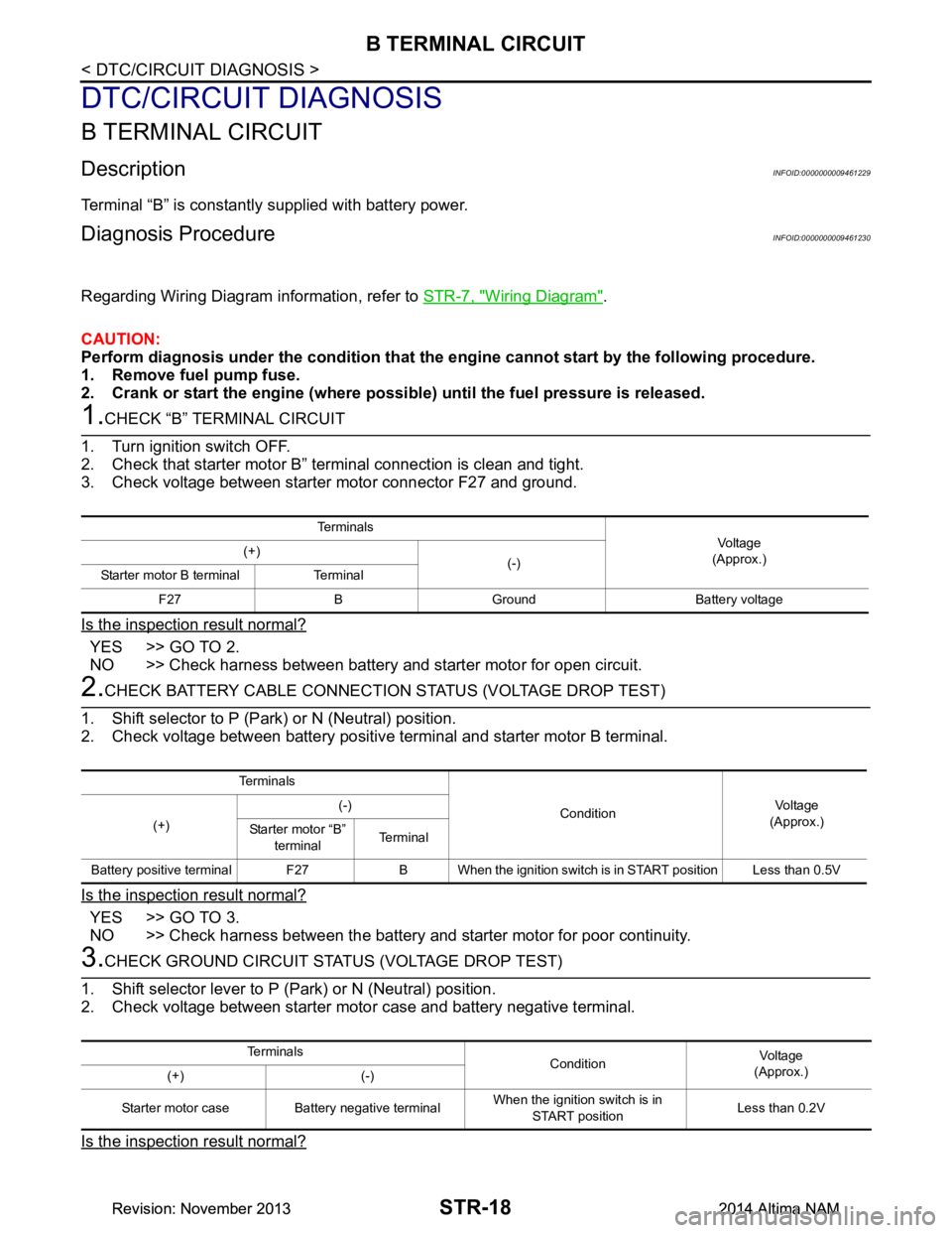
1.CHECK “B” TERMINAL CIRCUIT
1. Turn ignition switch OFF.
2. Check that starter motor B” terminal connection is clean and tight.
3. Check voltage between starter motor connector F27 and ground.
Is the inspection result normal?
YES >> GO TO 2.
NO >> Check harness between battery and starter motor for open circuit.
2.CHECK BATTERY CABLE CONNECTION STATUS (VOLTAGE DROP TEST)
1. Shift selector to P (Park) or N (Neutral) position.
2. Check voltage between battery positive terminal and starter motor B terminal.
Is the inspection result normal?
YES >> GO TO 3.
NO >> Check harness between the battery and starter motor for poor continuity.
3.CHECK GROUND CIRCUIT STATUS (VOLTAGE DROP TEST)
1. Shift selector lever to P (Park) or N (Neutral) position.
2. Check voltage between starter motor case and battery negative terminal.
Is the inspection result normal?
Te r m i n a l s
Voltage
(Approx.)
(+)
(-)
Starter motor B terminal Terminal
F27 B Ground Battery voltage
Te r m i n a l s
ConditionVoltage
(Approx.)
(+) (-)
Starter motor “B” terminal Te r m i n a l
Battery positive terminal F27 B When the ignition switch is in START position Less than 0.5V
Te r m i n a l s ConditionVoltage
(Approx.)
(+) (-)
Starter motor case Battery negative terminal When the ignition switch is in
START position Less than 0.2V
Revision: November 20132014 Altima NAMRevision: November 20132014 Altima NAM
Page 4210 of 4801
STR-20
< DTC/CIRCUIT DIAGNOSIS >
S CONNECTOR CIRCUIT
S CONNECTOR CIRCUIT
DescriptionINFOID:0000000009461231
The starter motor magnetic switch is supplied with power when the ignition switch is turned to the START posi-
tion while the selector lever is in the P (Park) or N (Neutral) position.
Diagnosis ProcedureINFOID:0000000009461232
Regarding Wiring Diagram information, refer to STR-7, "Wiring Diagram".
CAUTION:
Perform diagnosis under the condi tion that engine cannot start by the following procedure.
1. Remove fuel pump fuse.
2. Crank or start the engine (where possi ble) until the fuel pressure is released.
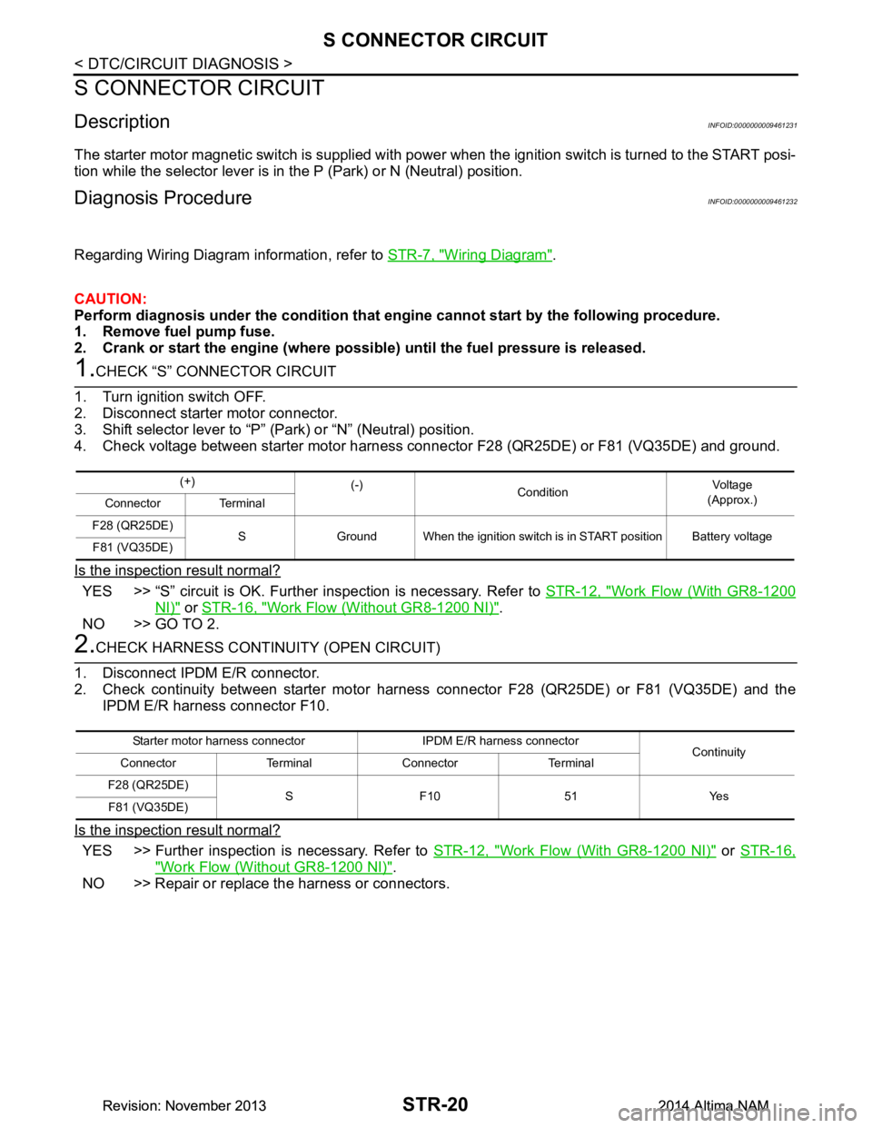
1.CHECK “S” CONNECTOR CIRCUIT
1. Turn ignition switch OFF.
2. Disconnect starter motor connector.
3. Shift selector lever to “P” (Park) or “N” (Neutral) position.
4. Check voltage between starter motor harness con nector F28 (QR25DE) or F81 (VQ35DE) and ground.
Is the inspection result normal?
YES >> “S” circuit is OK. Further inspection is necessary. Refer to STR-12, "Work Flow (With GR8-1200
NI)" or STR-16, "Work Flow (Without GR8-1200 NI)".
NO >> GO TO 2.
2.CHECK HARNESS CONTI NUITY (OPEN CIRCUIT)
1. Disconnect IPDM E/R connector.
2. Check continuity between starter motor harness connector F28 (QR25DE) or F81 (VQ35DE) and the
IPDM E/R harness connector F10.
Is the inspection result normal?
YES >> Further inspection is necessary. Refer to STR-12, "Work Flow (With GR8-1200 NI)" or STR-16,
"Work Flow (Without GR8-1200 NI)".
NO >> Repair or replace the harness or connectors.
(+) (-)
Condition Voltage
(Approx.)
Connector Terminal
F28 (QR25DE) S Ground When the ignition switch is in START position Battery voltage
F81 (VQ35DE)
Starter motor harness connector IPDM E/R harness connector Continuity
Connector Terminal Connector Terminal
F28 (QR25DE) S F10 51 Yes
F81 (VQ35DE)
Revision: November 20132014 Altima NAMRevision: November 20132014 Altima NAM
Page 4224 of 4801
![NISSAN TEANA 2014 Service Manual
PRECAUTIONSTM-9
< PRECAUTION > [CVT: RE0F10D]
C
EF
G H
I
J
K L
M A
B
TM
N
O P
PRECAUTION
PRECAUTIONS
Precaution for Supplemental Restraint System (SRS) "AIR BAG" and "SEAT BELT
PRE-TENSIONER"
INFO NISSAN TEANA 2014 Service Manual
PRECAUTIONSTM-9
< PRECAUTION > [CVT: RE0F10D]
C
EF
G H
I
J
K L
M A
B
TM
N
O P
PRECAUTION
PRECAUTIONS
Precaution for Supplemental Restraint System (SRS) "AIR BAG" and "SEAT BELT
PRE-TENSIONER"
INFO](/manual-img/5/57390/w960_57390-4223.png)
PRECAUTIONSTM-9
< PRECAUTION > [CVT: RE0F10D]
C
EF
G H
I
J
K L
M A
B
TM
N
O P
PRECAUTION
PRECAUTIONS
Precaution for Supplemental Restraint System (SRS) "AIR BAG" and "SEAT BELT
PRE-TENSIONER"
INFOID:0000000009951696
The Supplemental Restraint System such as “A IR BAG” and “SEAT BELT PRE-TENSIONER”, used along
with a front seat belt, helps to reduce the risk or severi ty of injury to the driver and front passenger for certain
types of collision. Information necessary to service t he system safely is included in the SR and SB section of
this Service Manual.
WARNING:
• To avoid rendering the SRS inoper ative, which could increase the risk of personal injury or death in
the event of a collision which would result in air bag inflation, all maintenance must be performed by
an authorized NISSAN/INFINITI dealer.
• Improper maintenance, including in correct removal and installation of the SRS, can lead to personal
injury caused by unintentional act ivation of the system. For removal of Spiral Cable and Air Bag
Module, see the SR section.
• Do not use electrical test equipm ent on any circuit related to the SRS unless instructed to in this
Service Manual. SRS wiring harnesses can be identi fied by yellow and/or orange harnesses or har-
ness connectors.
PRECAUTIONS WHEN USING POWER TOOLS (AIR OR ELECTRIC) AND HAMMERS
WARNING:
• When working near the Airbag Diagnosis Sensor Un it or other Airbag System sensors with the Igni-
tion ON or engine running, DO NOT use air or el ectric power tools or strike near the sensor(s) with a
hammer. Heavy vibration could activate the sensor( s) and deploy the air bag(s), possibly causing
serious injury.
• When using air or electric power tools or hammers , always switch the Ignition OFF, disconnect the
battery and wait at least three mi nutes before performing any service.
Precaution for Procedure without Cowl Top CoverINFOID:0000000009463955
When performing the procedure after removing cowl top cover, cover
the lower end of windshield with urethane, etc to prevent damage to
windshield.
Precaution for TCM and Tran saxle Assembly ReplacementINFOID:0000000009463956
CAUTION:
• To replace TCM, refer to TM-80, "Description"
.
• To replace transaxle assembly, refer to TM-81, "Description"
.
PIIB3706J
Revision: November 20132014 Altima NAMRevision: November 20132014 Altima NAM
Page 4225 of 4801
![NISSAN TEANA 2014 Service Manual
TM-10
< PRECAUTION >[CVT: RE0F10D]
PRECAUTIONS
General Precautions
INFOID:0000000009463957
• Turn ignition switch OFF an d disconnect the battery cable
from the negative terminal before connecting NISSAN TEANA 2014 Service Manual
TM-10
< PRECAUTION >[CVT: RE0F10D]
PRECAUTIONS
General Precautions
INFOID:0000000009463957
• Turn ignition switch OFF an d disconnect the battery cable
from the negative terminal before connecting](/manual-img/5/57390/w960_57390-4224.png)
TM-10
< PRECAUTION >[CVT: RE0F10D]
PRECAUTIONS
General Precautions
INFOID:0000000009463957
• Turn ignition switch OFF an d disconnect the battery cable
from the negative terminal before connecting or disconnect-
ing the CVT assembly harness connector. Because battery
voltage is applied to TCM even if ignition switch is turned
OFF.
• When connecting or disconnect ing pin connectors into or
from TCM, do not damage pin terminals (bend or break).
Check that there are not any bends or breaks on TCM pin ter-
minal, when connect ing pin connectors.
• Perform TCM input/output si gnal inspection and check
whether TCM functions normally or not before replacing TCM.
Refer to TM-49, "Reference Value"
.
• Perform “DTC (Diagnostic Trouble Code) CONFIRMATION
PROCEDURE”.
If the repair is completed DTC should not be displayed in the
“DTC CONFIRMATION PROCEDURE”.
• Always use the specified brand of CVT fluid. Refer to MA-11, "FOR USA AND CANADA : Fluids and Lubri-
cants".
• Use lint-free paper not cloth rags during work.
• Dispose of the waste oil using the methods prescribed by law, ordinance, etc. after replacing the CVT fluid.
SEF289H
AAT470A
MEF040DA
JSBIA1315ZZ
Revision: November 20132014 Altima NAMRevision: November 20132014 Altima NAM