2014 NISSAN TEANA ignition
[x] Cancel search: ignitionPage 4124 of 4801
POWER SUPPLY AND GROUND CIRCUITST-21
< DTC/CIRCUIT DIAGNOSIS >
C
D E
F
H I
J
K L
M A
B
ST
N
O P
DTC/CIRCUIT DIAGNOSIS
POWER SUPPLY AND GROUND CIRCUIT
A/C AUTO AMP.
A/C AUTO AMP. : Diagnosis ProcedureINFOID:0000000009952472
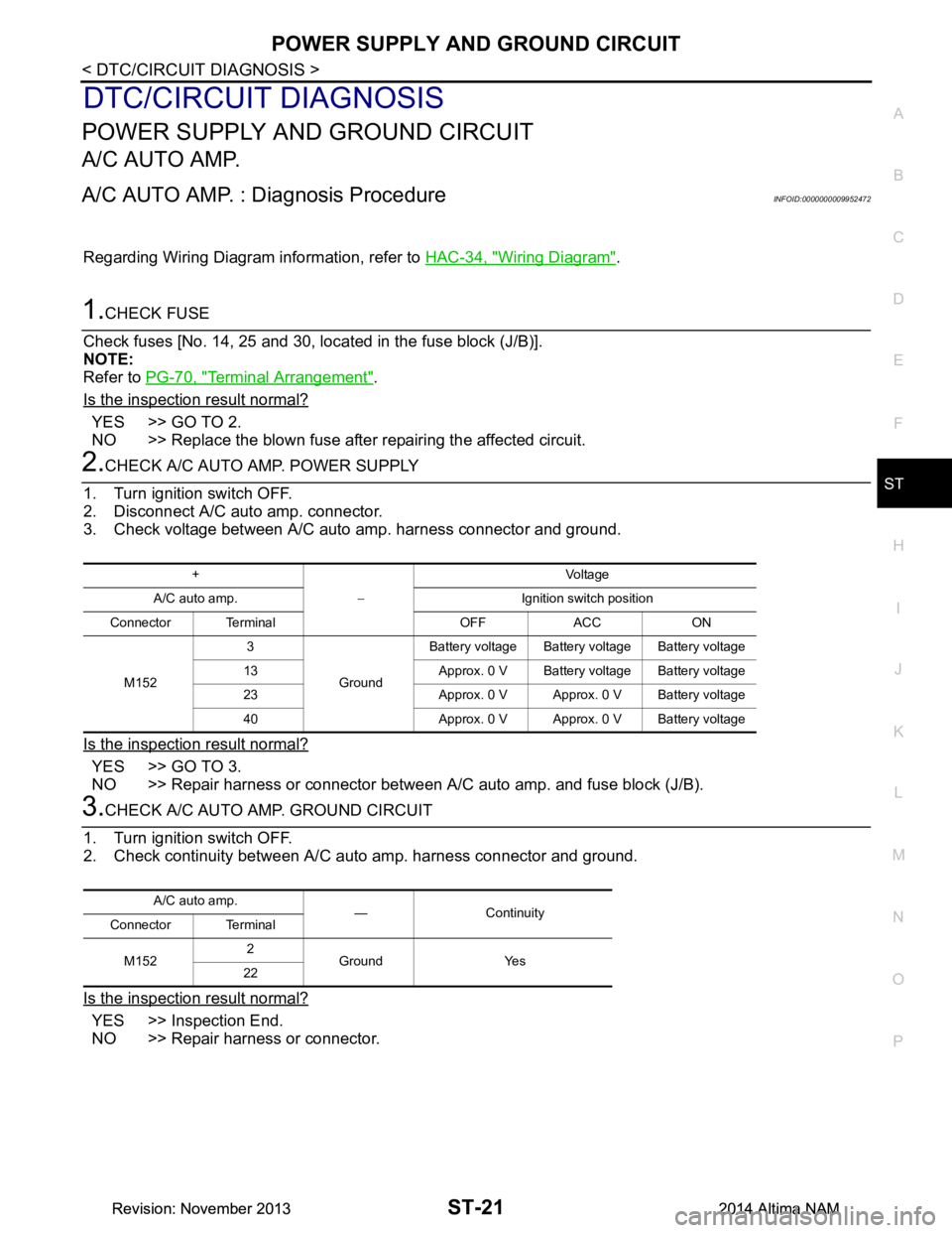
Regarding Wiring Diagram information, refer to HAC-34, "Wiring Diagram".
1.CHECK FUSE
Check fuses [No. 14, 25 and 30, loca ted in the fuse block (J/B)].
NOTE:
Refer to PG-70, "Terminal Arrangement"
.
Is the inspection result normal?
YES >> GO TO 2.
NO >> Replace the blown fuse after repairing the affected circuit.
2.CHECK A/C AUTO AMP. POWER SUPPLY
1. Turn ignition switch OFF.
2. Disconnect A/C auto amp. connector.
3. Check voltage between A/C auto amp. harness connector and ground.
Is the inspection result normal?
YES >> GO TO 3.
NO >> Repair harness or connector between A/C auto amp. and fuse block (J/B).
3.CHECK A/C AUTO AMP. GROUND CIRCUIT
1. Turn ignition switch OFF.
2. Check continuity between A/C aut o amp. harness connector and ground.
Is the inspection result normal?
YES >> Inspection End.
NO >> Repair harness or connector.
+
− Voltag e
A/C auto amp. Ignition switch position
Connector Terminal OFF ACC ON
M152 3
GroundBattery voltage Battery voltage Battery voltage
13 Approx. 0 V Battery voltage Battery voltage
23 Approx. 0 V Approx. 0 V Battery voltage
40 Approx. 0 V Approx. 0 V Battery voltage
A/C auto amp. — Continuity
Connector Terminal
M152 2
Ground Yes
22
Revision: November 20132014 Altima NAMRevision: November 20132014 Altima NAM
Page 4125 of 4801
ST-22
< DTC/CIRCUIT DIAGNOSIS >
HEATED STEERING WHEEL SYSTEM
HEATED STEERING WHEEL SYSTEM
Component Function CheckINFOID:0000000009461257
1.CHECK HEATED STEERING WHEEL SYSTEM
Check operation of heated steering wheel system. Refer to ST-8, "HEATED STEERING WHEEL SYSTEM :
System Description".
Is the inspection result normal?
YES >> Inspection End.
NO >> Go to ST-22, "Diagnosis Procedure"
.
Diagnosis ProcedureINFOID:0000000009461258
Regarding Wiring Diagram information, refer to ST-10, "Wiring Diagram".
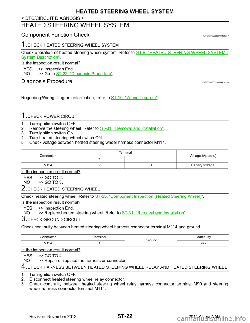
1.CHECK POWER CIRCUIT
1. Turn ignition switch OFF.
2. Remove the steering wheel. Refer to ST-31, "Removal and Installation"
.
3. Turn ignition switch ON.
4. Turn heated steering wheel switch ON.
5. Check voltage between heated steering wheel harness connector M114.
Is the inspection result normal?
YES >> GO TO 2.
NO >> GO TO 3.
2.CHECK HEATED STEERING WHEEL
Check heated steering wheel. Refer to ST-25, "Component Inspection (Heated Steering Wheel)"
.
Is the inspection result normal?
YES >> Inspection End.
NO >> Replace heated steering wheel. Refer to ST-31, "Removal and Installation"
.
3.CHECK GROUND CIRCUIT
Check continuity between heated steering wheel harness connector terminal M114 and ground.
Is the inspection result normal?
YES >> GO TO 4.
NO >> Repair or replace the harness or connector.
4.CHECK HARNESS BETWEEN HEATED STEERING WHEEL RELAY AND HEATED STEERING WHEEL
1. Turn ignition switch OFF.
2. Disconnect heated steering wheel relay connector.
3. Check continuity between heated steering wheel relay harness connector terminal M90 and steering
wheel harness connector terminal M114.
Connector Te r m i n a l
Voltage (Approx.)
+-
M114 2 1 Battery voltage
Connector Terminal GroundContinuity
M114 1 Yes
Revision: November 20132014 Altima NAMRevision: November 20132014 Altima NAM
Page 4127 of 4801
ST-24
< DTC/CIRCUIT DIAGNOSIS >
HEATED STEERING WHEEL SYSTEM
NO >> Repair or replace harness or connector.
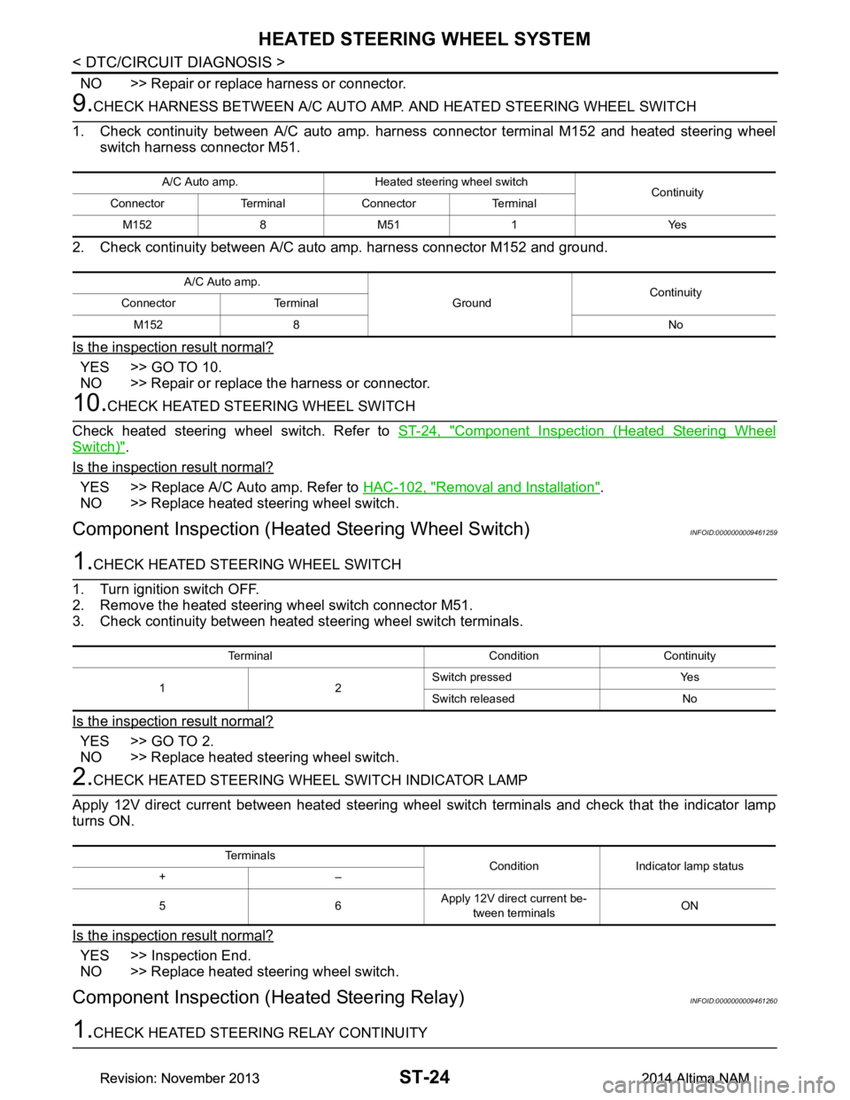
9.CHECK HARNESS BETWEEN A/C AUTO AMP. AND HEATED STEERING WHEEL SWITCH
1. Check continuity between A/C auto amp. har ness connector terminal M152 and heated steering wheel
switch harness connector M51.
2. Check continuity between A/C auto amp. harness connector M152 and ground.
Is the inspection result normal?
YES >> GO TO 10.
NO >> Repair or replace the harness or connector.
10.CHECK HEATED STEERING WHEEL SWITCH
Check heated steering wheel switch. Refer to ST-24, "Component Inspection (Heated Steering Wheel
Switch)".
Is the inspection result normal?
YES >> Replace A/C Auto amp. Refer to HAC-102, "Removal and Installation".
NO >> Replace heated steering wheel switch.
Component Inspection (Heat ed Steering Wheel Switch)INFOID:0000000009461259
1.CHECK HEATED STEERING WHEEL SWITCH
1. Turn ignition switch OFF.
2. Remove the heated steering wheel switch connector M51.
3. Check continuity between heated st eering wheel switch terminals.
Is the inspection result normal?
YES >> GO TO 2.
NO >> Replace heated steering wheel switch.
2.CHECK HEATED STEERING WH EEL SWITCH INDICATOR LAMP
Apply 12V direct current between heated steering wheel switch terminals and check that the indicator lamp
turns ON.
Is the inspection result normal?
YES >> Inspection End.
NO >> Replace heated steering wheel switch.
Component Inspection (Heated Steering Relay)INFOID:0000000009461260
1.CHECK HEATED STEERING RELAY CONTINUITY
A/C Auto amp. Heated steering wheel switch
Continuity
Connector Terminal Connector Terminal
M152 8 M51 1 Yes
A/C Auto amp. GroundContinuity
Connector Terminal
M152 8 No
Terminal Condition Continuity
12 Switch pressed Yes
Switch released No
Te r m i n a l s Condition Indicator lamp status
+–
56 Apply 12V direct current be-
tween terminals ON
Revision: November 20132014 Altima NAMRevision: November 20132014 Altima NAM
Page 4128 of 4801
HEATED STEERING WHEEL SYSTEMST-25
< DTC/CIRCUIT DIAGNOSIS >
C
D E
F
H I
J
K L
M A
B
ST
N
O P
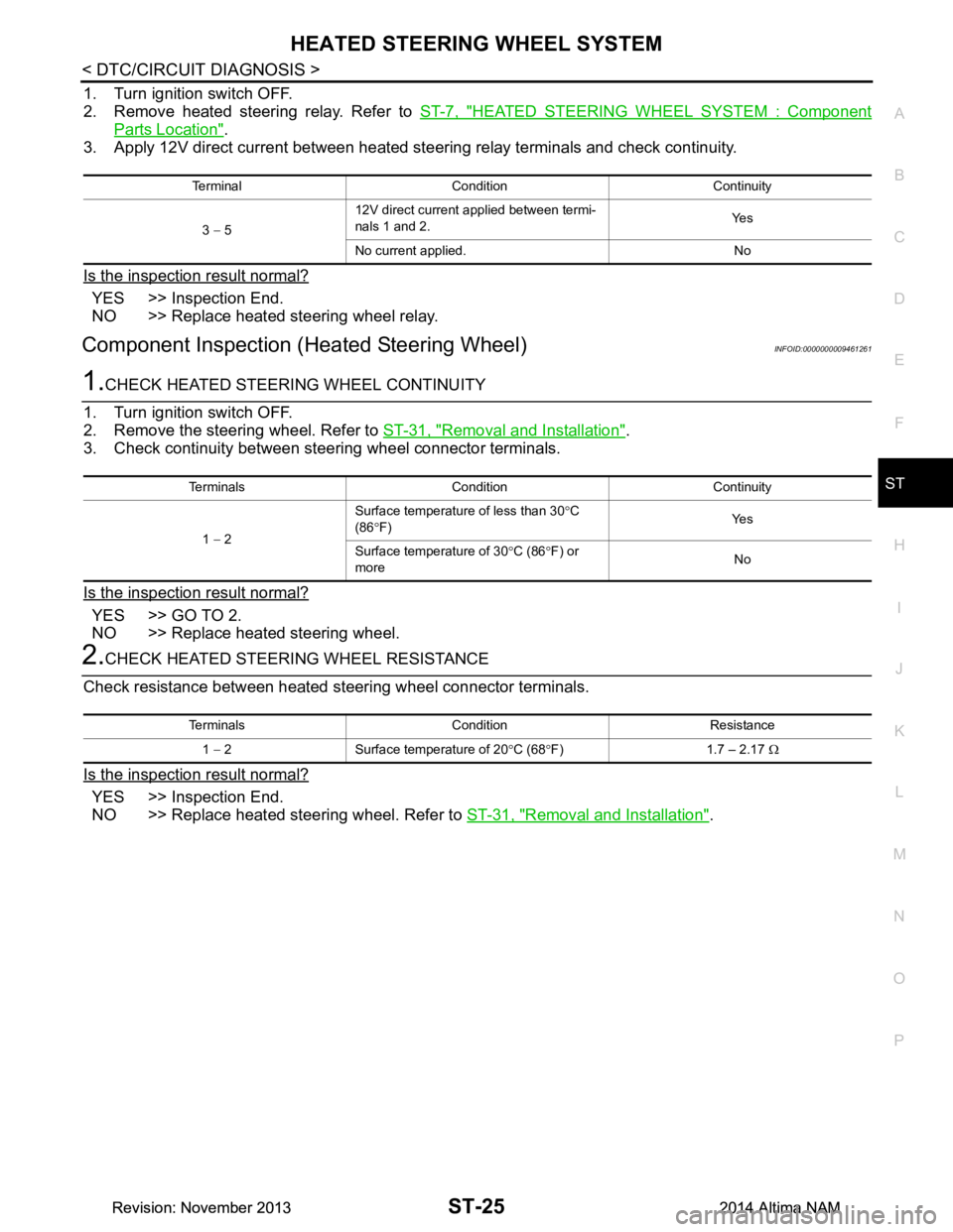
1. Turn ignition switch OFF.
2. Remove heated steering relay. Refer to ST-7, "HEATED STEERING WHEEL SYSTEM : Component
Parts Location".
3. Apply 12V direct current between heated steering relay terminals and check continuity.
Is the inspection result normal?
YES >> Inspection End.
NO >> Replace heated steering wheel relay.
Component Inspection (H eated Steering Wheel)INFOID:0000000009461261
1.CHECK HEATED STEERING WHEEL CONTINUITY
1. Turn ignition switch OFF.
2. Remove the steering wheel. Refer to ST-31, "Removal and Installation"
.
3. Check continuity between steering wheel connector terminals.
Is the inspection result normal?
YES >> GO TO 2.
NO >> Replace heated steering wheel.
2.CHECK HEATED STEERING WHEEL RESISTANCE
Check resistance between heated steering wheel connector terminals.
Is the inspection result normal?
YES >> Inspection End.
NO >> Replace heated steering wheel. Refer to ST-31, "Removal and Installation"
.
Terminal Condition Continuity
3 − 5 12V direct current applied between termi-
nals 1 and 2. Ye s
No current applied. No
Terminals Condition Continuity
1 − 2 Surface temperature of less than 30
°C
(86 °F) Ye s
Surface temperature of 30 °C (86 °F) or
more No
Terminals Condition Resistance
1 − 2 Surface temperature of 20 °C (68 °F) 1.7 – 2.17 Ω
Revision: November 20132014 Altima NAMRevision: November 20132014 Altima NAM
Page 4129 of 4801

ST-26
< DTC/CIRCUIT DIAGNOSIS >
HEATED STEERING WHEEL SWITCH INDICATOR LAMP
HEATED STEERING WHEEL SWITCH INDICATOR LAMP
Component Function CheckINFOID:0000000009461262
1.CHECK HEATED STEERING WHEEL SWITCH INDICATOR LAMP
1. Turn ignition switch ON.
2. Turn heated steering wheel switch ON. Observe indicator.
3. Turn heated steering wheel switch OFF. Observe indicator.
Does heated steering wheel switch indicator lamp turn ON and then OFF?
YES >> Inspection End.
NO >> Go to ST-26, "Diagnosis Procedure"
.
Diagnosis ProcedureINFOID:0000000009461263
1.CHECK POWER CIRCUIT
1. Turn ignition switch OFF.
2. Remove the heated steering wheel switch.
3. Turn ignition switch ON.
4. Check voltage between heated steering wheel switch harness connector M51.
Is the inspection result normal?
YES >> GO TO 2.
NO >> GO TO 3.
2.CHECK GROUND CIRCUIT
1. Turn ignition switch OFF.
2. Disconnect heated steering wheel switch connector.
3. Check continuity between heated steering wheel switch harness connector terminal M51 and ground.
Is the inspection result normal?
YES >> GO TO 3.
NO >> Repair or replace the harness or connectors.
3.CHECK HARNESS BETWEEN HEATED STEERING RELAY AND HEATED STEERING WHEEL SWITCH
1. Disconnect heated steering relay connector.
2. Check continuity between heated steering rela y harness connector terminal M90 and heated steering
wheel switch harness connector M51.
3. Check continuity between heated steer ing relay harness connector M90 and ground.
Is the inspection result normal?
YES >> GO TO 4.
NO >> Repair or replace harness or connectors.
Connector Te r m i n a l
Voltage (Approx.)
+-
M51 1 2 Battery voltage
Connector Terminal GroundContinuity
M51 6 Yes
Heated steering relay Heated steering wheel switch Continuity
Connector Terminal Connector Terminal
M90 5 M51 5 Yes
Connector Terminal GroundContinuity
M90 5 No
Revision: November 20132014 Altima NAMRevision: November 20132014 Altima NAM
Page 4137 of 4801
ST-34
< REMOVAL AND INSTALLATION >
STEERING COLUMN
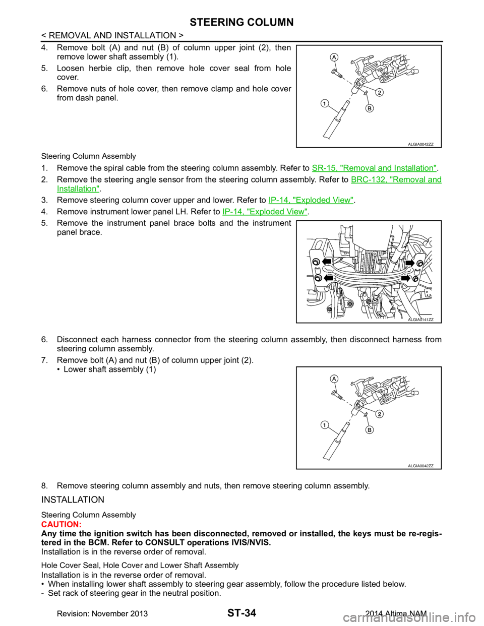
4. Remove bolt (A) and nut (B) of column upper joint (2), thenremove lower shaft assembly (1).
5. Loosen herbie clip, then remove hole cover seal from hole cover.
6. Remove nuts of hole cover, then remove clamp and hole cover from dash panel.
Steering Column Assembly
1. Remove the spiral cable from the steering column assembly. Refer to SR-15, "Removal and Installation".
2. Remove the steering angle sensor from the steering column assembly. Refer to BRC-132, "Removal and
Installation".
3. Remove steering column cover upper and lower. Refer to IP-14, "Exploded View"
.
4. Remove instrument lower panel LH. Refer to IP-14, "Exploded View"
.
5. Remove the instrument panel brace bolts and the instrument panel brace.
6. Disconnect each harness connector from the steeri ng column assembly, then disconnect harness from
steering column assembly.
7. Remove bolt (A) and nut (B) of column upper joint (2). • Lower shaft assembly (1)
8. Remove steering column assembly and nuts, then remove steering column assembly.
INSTALLATION
Steering Column Assembly
CAUTION:
Any time the ignition switch has been disconnected, removed or inst alled, the keys must be re-regis-
tered in the BCM. Refer to CONSULT operations IVIS/NVIS.
Installation is in the reverse order of removal.
Hole Cover Seal, Hole Cove r and Lower Shaft Assembly
Installation is in the reverse order of removal.
• When installing lower shaft assembly to steering gear assembly, follow the procedure listed below.
- Set rack of steering gear in the neutral position.
ALGIA0042ZZ
ALGIA0141ZZ
ALGIA0042ZZ
Revision: November 20132014 Altima NAMRevision: November 20132014 Altima NAM
Page 4154 of 4801
PRECAUTIONSSTC-3
< PRECAUTION >
C
D E
F
H I
J
K L
M A
B
STC
N
O P
PRECAUTION
PRECAUTIONS
Precaution for Supplemental Restraint System (SRS) "AIR BAG" and "SEAT BELT
PRE-TENSIONER"
INFOID:0000000009951730
The Supplemental Restraint System such as “A IR BAG” and “SEAT BELT PRE-TENSIONER”, used along
with a front seat belt, helps to reduce the risk or severi ty of injury to the driver and front passenger for certain
types of collision. Information necessary to service t he system safely is included in the SR and SB section of
this Service Manual.
WARNING:
• To avoid rendering the SRS inoper ative, which could increase the risk of personal injury or death in
the event of a collision which would result in air bag inflation, all maintenance must be performed by
an authorized NISSAN/INFINITI dealer.
• Improper maintenance, including in correct removal and installation of the SRS, can lead to personal
injury caused by unintentional act ivation of the system. For removal of Spiral Cable and Air Bag
Module, see the SR section.
• Do not use electrical test equipm ent on any circuit related to the SRS unless instructed to in this
Service Manual. SRS wiring harnesses can be identi fied by yellow and/or orange harnesses or har-
ness connectors.
PRECAUTIONS WHEN USING POWER TOOLS (AIR OR ELECTRIC) AND HAMMERS
WARNING:
• When working near the Airbag Diagnosis Sensor Un it or other Airbag System sensors with the Igni-
tion ON or engine running, DO NOT use air or el ectric power tools or strike near the sensor(s) with a
hammer. Heavy vibration could activate the sensor( s) and deploy the air bag(s), possibly causing
serious injury.
• When using air or electric power tools or hammers , always switch the Ignition OFF, disconnect the
battery and wait at least three mi nutes before performing any service.
Service Notice and Precautions for Hydrau lic Pump Electric Power Steering System
INFOID:0000000009460340
• Check each tire for proper air pressure and size. Refer to WT-60, "Tire".
• Verify that the steering system components are G enuine NISSAN parts and have been installed properly.
• Check the steering column for loose mounting bolts.
• Check the steering gear assembly for loose mounting bolts. Check the inner sockets and outer sockets for
damage or wear. Inspect the boots and seals for leakage of power steering fluid.
• Verify proper wheel alignment. Refer to FSU-7, "Inspection and Adjustment"
.
• Check for any damage, wear, or modification to the suspension and body that would result in increased
weight or an improper wheelarch height. Refer to FSU-26, "Wheelarch Height (Unladen*
1)".
• Check for proper battery voltage.
• Verify that all power steering pump assembly connections are clean and fully seated.
• Verify that only Genuine NISSAN E-PSF is used. Use of any power steering fluid other than Genuine NIS-
SAN E-PSF will prevent the power st eering system from proper operation.
• An audible high pitch noise may be heard from the engine compartment when the steering wheel is oper-
ated, particularly at low speeds such as a parking lot maneuver. This condition is not a malfunction, rather
normal system operation. Steering at low speeds or parking lot maneuvers demands higher hydraulic assis-
tance, resulting in larger power st eering pump load and increased system noise.
• The power steering pump is electrically controlled by the power steering control module.
• Before connecting or disconnecting the power steeri ng control module harness connectors, turn ignition
switch “OFF” and disconnect battery ground cable. Batter y voltage is applied to power steering control mod-
ule even if ignition switch is turned “OFF”.
Revision: November 20132014 Altima NAMRevision: November 20132014 Altima NAM
Page 4159 of 4801
STC-8
< SYSTEM DESCRIPTION >
SYSTEM
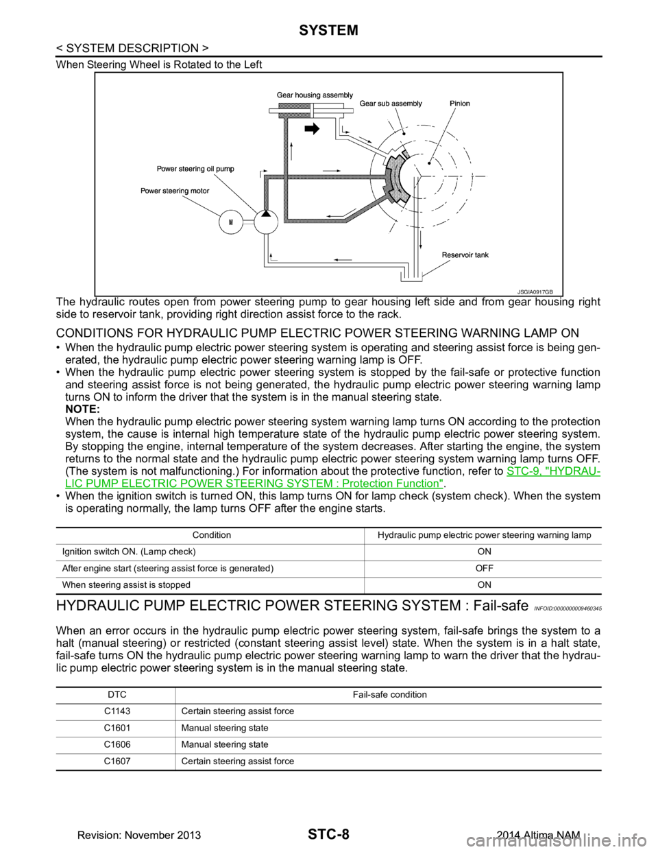
When Steering Wheel is Rotated to the Left
The hydraulic routes open from power steering pump to gear housing left side and from gear housing right
side to reservoir tank, providing right direction assist force to the rack.
CONDITIONS FOR HYDRAULIC PUMP ELECTR IC POWER STEERING WARNING LAMP ON
• When the hydraulic pump electric power steering syst em is operating and steering assist force is being gen-
erated, the hydraulic pump electric power steering warning lamp is OFF.
• When the hydraulic pump electric power steering system is stopped by the fail-safe or protective function
and steering assist force is not being generated, the hy draulic pump electric power steering warning lamp
turns ON to inform the driver that t he system is in the manual steering state.
NOTE:
When the hydraulic pump electric power steering system warning lamp turns ON according to the protection
system, the cause is internal high temperature state of the hydraulic pump electric power steering system.
By stopping the engine, internal temperature of the s ystem decreases. After starting the engine, the system
returns to the normal state and the hydraulic pump elec tric power steering system warning lamp turns OFF.
(The system is not malfunctioning.) For informat ion about the protective function, refer to STC-9, "HYDRAU-
LIC PUMP ELECTRIC POWER STEERING SYSTEM : Protection Function".
• When the ignition switch is turned ON, this lamp turn s ON for lamp check (system check). When the system
is operating normally, the lamp turns OFF after the engine starts.
HYDRAULIC PUMP ELECTRIC POWE R STEERING SYSTEM : Fail-safeINFOID:0000000009460345
When an error occurs in the hydraulic pump electric pow er steering system, fail-safe brings the system to a
halt (manual steering) or restricted (constant steering assi st level) state. When the system is in a halt state,
fail-safe turns ON the hydraulic pump electric power steer ing warning lamp to warn the driver that the hydrau-
lic pump electric power steering system is in the manual steering state.
JSGIA0917GB
Condition Hydraulic pump electric power steering warning lamp
Ignition switch ON. (Lamp check) ON
After engine start (steering assist force is generated) OFF
When steering assist is stopped ON
DTC Fail-safe condition
C1143 Certain steering assist force
C1601 Manual steering state
C1606 Manual steering state
C1607 Certain steering assist force
Revision: November 20132014 Altima NAMRevision: November 20132014 Altima NAM