2014 NISSAN TEANA sensor
[x] Cancel search: sensorPage 3977 of 4801
SPIRAL CABLESR-15
< REMOVAL AND INSTALLATION >
C
D E
F
G
I
J
K L
M A
B
SR
N
O P
SPIRAL CABLE
Removal and InstallationINFOID:0000000009463071
WARNING:
• Before servicing the SRS, turn ignition switch OFF, disconnect both battery terminals and wait at
least three minutes.
• Do not use air tools or electric tools for servicing.
REMOVAL
1. Disconnect both the negative and positive battery terminal s, then wait at least three minutes. Refer to PG-
73, "Removal and Installation (Battery)".
2. Remove the steering wheel. Refer to ST-31, "Removal and Installation"
.
3. Remove the steering column lower cover and position steering column upper cover aside. Refer to IP-17,
"Removal and Installation".
4. Remove the paddle shifter (if equipped). Refer to TM-382, "Removal and Installation"
.
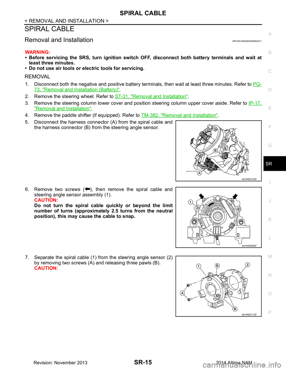
5. Disconnect the harness connector (A) from the spiral cable and the harness connector (B) from the steering angle sensor.
6. Remove two screws ( ), then remove the spiral cable and steering angle sensor assembly (1).
CAUTION:
Do not turn the spiral cable quickly or beyond the limit
number of turns (approximately 2.5 turns from the neutral
position), this may cause the cable to snap.
7. Separate the spiral cable (1) from the steering angle sensor (2) by removing two screws (A) and releasing three pawls (B).
CAUTION:
ALHIA0272ZZ
ALHIA0269ZZ
ALHIA0271ZZ
Revision: November 20132014 Altima NAM
Page 3984 of 4801
SR-22
< REMOVAL AND INSTALLATION >
CRASH ZONE SENSOR
CRASH ZONE SENSOR
Removal and InstallationINFOID:0000000009463077
REMOVAL
WARNING:
• Before servicing the SRS, turn ig nition switch OFF, disconnect both battery terminals and wait at
least three minutes.
• Do not use air tools or el ectric tools for servicing.
1. Disconnect the negative and positive battery terminals, then wait at least three minutes. Refer to PG-73,
"Removal and Installation (Battery)".
2. Remove the front air duct. Refer to EM-144, "Removal and Installation"
(VQ35DE) or EM-29, "Removal
and Installation" (QR25DE).
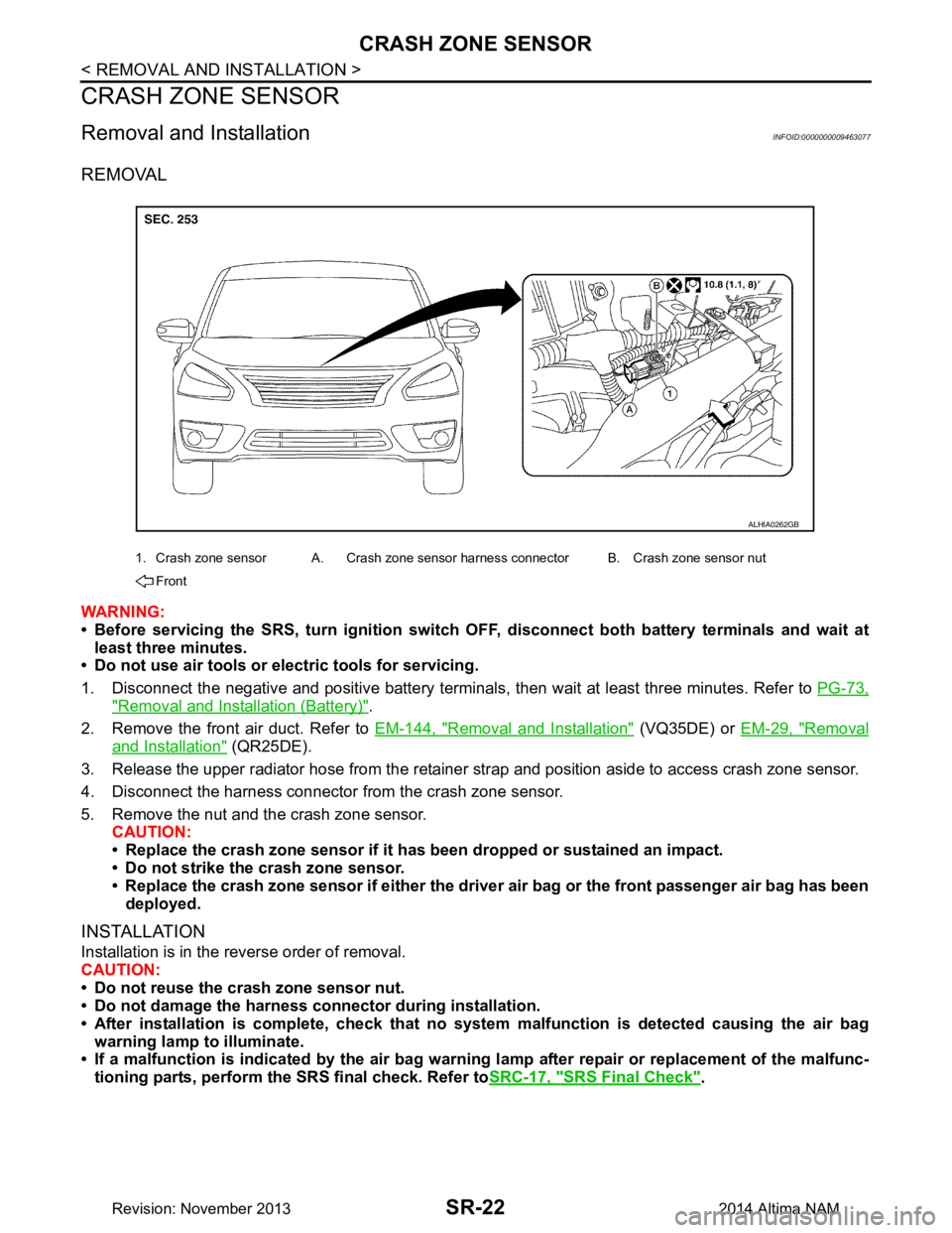
3. Release the upper radiator hose from the retainer strap and position aside to access crash zone sensor.
4. Disconnect the harness connector from the crash zone sensor.
5. Remove the nut and the crash zone sensor. CAUTION:
• Replace the crash zone sensor if it has been dropped or sustained an impact.
• Do not strike the crash zone sensor.
• Replace the crash zone sensor if either the dri ver air bag or the front passenger air bag has been
deployed.
INSTALLATION
Installation is in the reverse order of removal.
CAUTION:
• Do not reuse the crash zone sensor nut.
• Do not damage the harness connector during installation.
• After installation is complete, check that no syst em malfunction is detected causing the air bag
warning lamp to illuminate.
• If a malfunction is indicated by the air bag warnin g lamp after repair or replacement of the malfunc-
tioning parts, perform the SRS final check. Refer to SRC-17, "SRS Final Check"
.
1. Crash zone sensor A. Crash zone sensor harness connector B. Crash zone sensor nut
Front
ALHIA0262GB
Revision: November 20132014 Altima NAM
Page 3985 of 4801
SIDE AIR BAG (SATELLITE) SENSOR
SR-23
< REMOVAL AND INSTALLATION >
C
D E
F
G
I
J
K L
M A
B
SR
N
O P
SIDE AIR BAG (S ATELLITE) SENSOR
Exploded ViewINFOID:0000000009463078
Removal and InstallationINFOID:0000000009463079
WARNING:
• Before servicing the SRS, turn ignition switch OFF, disconnect both battery terminals and wait at
least three minutes.
• Do not use air tools or electric tools for servicing.
FRONT DOOR (SATELLITE) SENSOR (LH/RH)
Removal
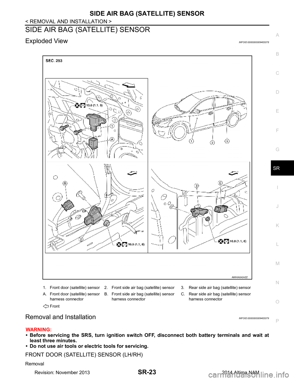
1. Front door (satellite) sensor 2. Front side air bag (satellite) sensor 3. Rear side air bag (satellite) sensor
A. Front door (satellite) sensor harness connector B. Front side air bag (satellite) sensor
harness connector C. Rear side air bag (satellite) sensor
harness connector
Front
AWHIA0424ZZ
Revision: November 20132014 Altima NAM
Page 3986 of 4801
SR-24
< REMOVAL AND INSTALLATION >
SIDE AIR BAG (SATELLITE) SENSOR
1. Disconnect both the negative and positive battery terminals, then wait at least three minutes. Refer to PG-
73, "Removal and Installation (Battery)".
2. Remove front door finisher. Refer to INT-15, "Removal and Installation"
.
3. Disconnect the harness connector from the front door (satellite) sensor.
4. Remove the bolts and the front door (satellite) sensor. CAUTION:
• Do not reuse the front door satellite sensor bolts.
• Replace the front door satellite sensor if it has been dropped or sustained an impact.
• Do not strike the front door satellite sensor.
Installation
Installation is in the reverse order of removal.
CAUTION:
• Do not reuse the front door (satellite) sensor bolts.
• Do not damage the harness connector or harness.
• After installation is complete, check that no syst em malfunction is detected causing the air bag
warning lamp to illuminate.
• If a malfunction is indicated by the air bag warnin g lamp after repair or replacement of the malfunc-
tioning parts, perform the SRS final check. Refer to SRC-17, "SRS Final Check"
.
FRONT SIDE AIR BAG (SATELLITE) SENSOR (LH/RH)
Removal
1. Disconnect both the negative and positive battery terminal s, then wait at least three minutes. Refer to PG-
73, "Removal and Installation (Battery)".
2. Remove the front seat belt retractor. Refer to SB-8, "Removal and Installation"
.
3. Disconnect the harness connector from the front side air bag (satellite) sensor.
4. Remove the nut and the front side air bag (satellite) sensor. CAUTION:
• Do not reuse the front side air bag (satellite) sensor nut.
• Replace the front side air bag (satellite) sensor if it has been dropped or sustained an impact.
• Do not strike the front side air bag (satellite) sensor.
Installation
Installation is in the reverse order of removal.
CAUTION:
• Do not reuse the front side air bag (satellite) sensor nut.
• Do not damage the harness connector or harness.
• After installation is complete, check that no syst em malfunction is detected causing the air bag
warning lamp to illuminate.
• If a malfunction is indicated by the air bag warnin g lamp after repair or replacement of the malfunc-
tioning parts, perform the SRS final check. Refer to SRC-17, "SRS Final Check"
.
REAR SIDE AIR BAG (SATELLITE) SENSOR (LH/RH)
Removal
1. Disconnect both the negative and positive battery terminal s, then wait at least three minutes. Refer to PG-
73, "Removal and Installation (Battery)".
2. Remove the rear kicking plate inner. Refer to INT-22, "REAR KICKING PLATE : Removal and Installation
- Inner".
3. Disconnect the harness connector from the rear side air bag (satellite) sensor.
4. Remove the nut and the rear side air bag (satellite) sensor. CAUTION:
• Do not reuse the rear side air bag (satellite) sensor nut.
• Replace the rear side air bag (satellite) sensor if it has been dropped or sustained an impact.
• Do not strike the rear side air bag (satellite) sensor.
Installation
Installation is in the reverse order of removal.
CAUTION:
• Do not reuse the rear side air bag (satellite) sensor nut.
Revision: November 20132014 Altima NAM
Page 3987 of 4801

SIDE AIR BAG (SATELLITE) SENSOR
SR-25
< REMOVAL AND INSTALLATION >
C
D E
F
G
I
J
K L
M A
B
SR
N
O P
• Do not damage the harness connector or harness.
• After installation is complete, check that no syst em malfunction is detected causing the air bag
warning lamp to illuminate.
• If a malfunction is indicated by the air bag warnin g lamp after repair or replacement of the malfunc-
tioning parts, perform the SRS final check. Refer to SRC-17, "SRS Final Check"
.
Revision: November 20132014 Altima NAM
Page 3988 of 4801
SR-26
< REMOVAL AND INSTALLATION >
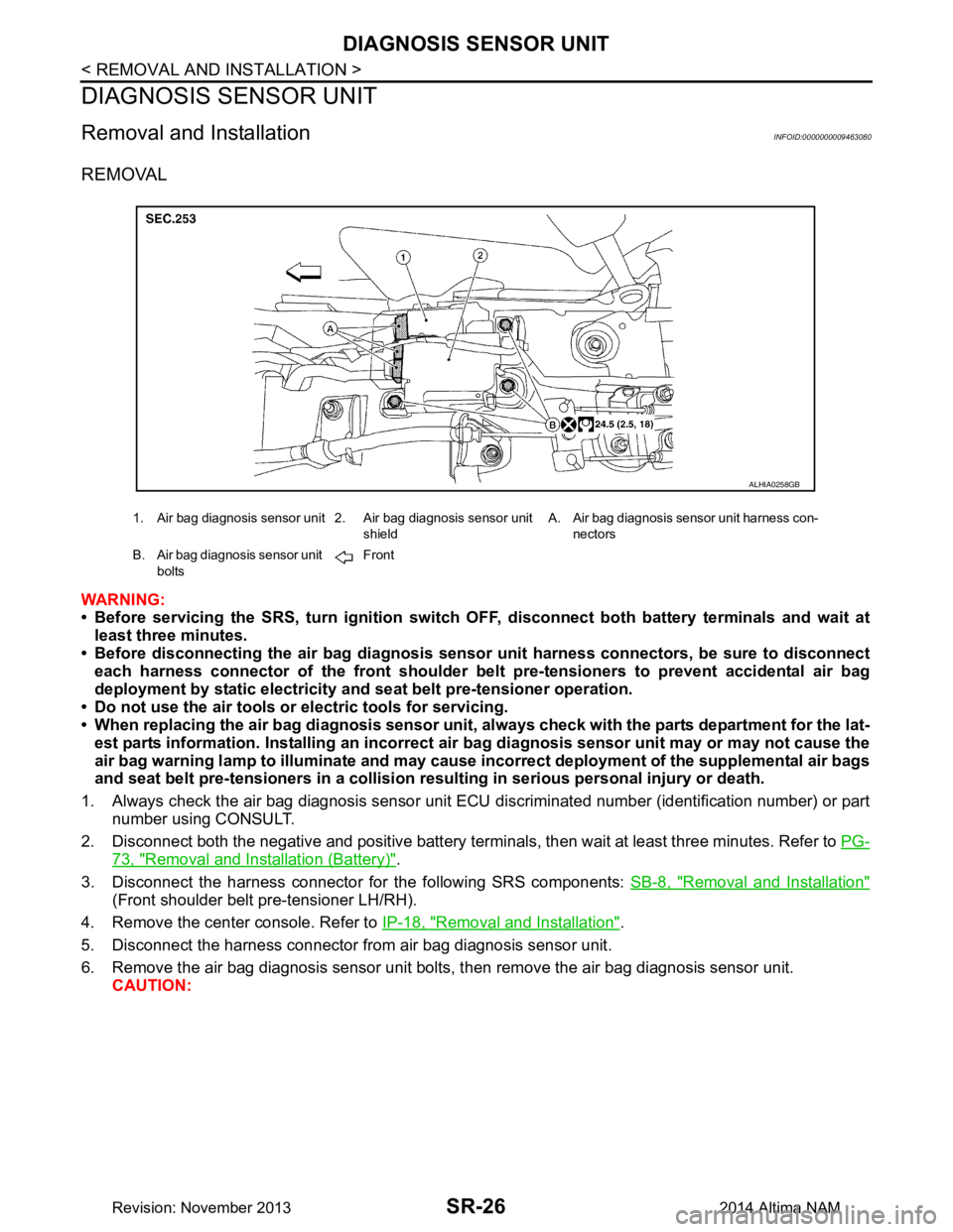
DIAGNOSIS SENSOR UNIT
DIAGNOSIS SENSOR UNIT
Removal and InstallationINFOID:0000000009463080
REMOVAL
WARNING:
• Before servicing the SRS, turn ig nition switch OFF, disconnect both battery terminals and wait at
least three minutes.
• Before disconnecting the air bag diagnosis sensor unit harness conn ectors, be sure to disconnect
each harness connector of the front shoulder belt pre-tensioners to prevent accidental air bag
deployment by static electricity and seat belt pre-tensioner operation.
• Do not use the air tools or electric tools for servicing.
• When replacing the air bag diagno sis sensor unit, always check with th e parts department for the lat-
est parts information. Installing an incorrect air bag diagnosis sen sor unit may or may not cause the
air bag warning lamp to illuminate and may cause in correct deployment of the supplemental air bags
and seat belt pre-tensioners in a collision r esulting in serious personal injury or death.
1. Always check the air bag diagnosis sensor unit ECU discriminated number (identification number) or part
number using CONSULT.
2. Disconnect both the negative and positive battery terminal s, then wait at least three minutes. Refer to PG-
73, "Removal and Installation (Battery)".
3. Disconnect the harness connector fo r the following SRS components: SB-8, "Removal and Installation"
(Front shoulder belt pre-tensioner LH/RH).
4. Remove the center console. Refer to IP-18, "Removal and Installation"
.
5. Disconnect the harness connector from air bag diagnosis sensor unit.
6. Remove the air bag diagnosis sensor unit bolts , then remove the air bag diagnosis sensor unit.
CAUTION:
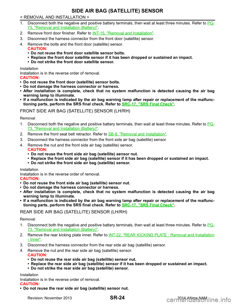
1. Air bag diagnosis sensor unit 2. Air bag diagnosis sensor unit
shieldA. Air bag diagnosis sensor unit harness con-
nectors
B. Air bag diagnosis sensor unit bolts Front
ALHIA0258GB
Revision: November 20132014 Altima NAM
Page 3989 of 4801
DIAGNOSIS SENSOR UNITSR-27
< REMOVAL AND INSTALLATION >
C
D E
F
G
I
J
K L
M A
B
SR
N
O P
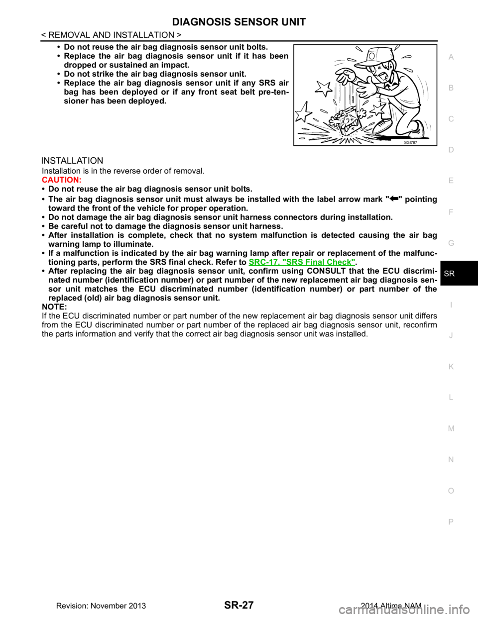
• Do not reuse the air bag di agnosis sensor unit bolts.
• Replace the air bag diagnosis sensor unit if it has been
dropped or sustained an impact.
• Do not strike the air ba g diagnosis sensor unit.
• Replace the air bag diagnosis sensor unit if any SRS air
bag has been deployed or if any front seat belt pre-ten-
sioner has been deployed.
INSTALLATION
Installation is in the reverse order of removal.
CAUTION:
• Do not reuse the air bag diagnosis sensor unit bolts.
• The air bag diagnosis sensor unit must always be installed with the label arrow mark " " pointing
toward the front of the vehicle for proper operation.
• Do not damage the air bag diagnosis sensor unit harness connectors during installation.
• Be careful not to damage the diagnosis sensor unit harness.
• After installation is complete, check that no syst em malfunction is detected causing the air bag
warning lamp to illuminate.
• If a malfunction is indicated by the air bag warnin g lamp after repair or replacement of the malfunc-
tioning parts, perform the SRS final check. Refer to SRC-17, "SRS Final Check"
.
• After replacing the air bag diagnosis sensor un it, confirm using CONSULT that the ECU discrimi-
nated number (identification number) or part nu mber of the new replacement air bag diagnosis sen-
sor unit matches the ECU discrimin ated number (identification number) or part number of the
replaced (old) air bag diagnosis sensor unit.
NOTE:
If the ECU discriminated number or pa rt number of the new replacement air bag diagnosis sensor unit differs
from the ECU discriminated number or part number of the replaced air bag diagnosis sensor unit, reconfirm
the parts information and verify that the corre ct air bag diagnosis sensor unit was installed.
SGI787
Revision: November 20132014 Altima NAM
Page 3990 of 4801
SR-28
< REMOVAL AND INSTALLATION >
OCCUPANT CLASSIFICATION SYSTEM
OCCUPANT CLASSIFICATION SYSTEM
Removal and InstallationINFOID:0000000009463081
OCCUPANT CLASSIFICATION SYSTEM CONTROL UNIT
WARNING:
• Before servicing the SRS, turn ig nition switch OFF, disconnect both battery terminals and wait at
least three minutes.
• Do not use air tools or el ectric tools for servicing.
Removal
1. Remove front passenger seat assembly. Refer to SE-30, "PASSENGER SIDE : Removal and Installation
- Seat Assembly".
2. Disconnect the harness connector from the oc cupant classification system control unit.
3. Remove occupant classification system control unit bolts.
4. Remove occupant classification system control unit. CAUTION:
• Replace the occupant classification control unit if it has been dropped or sustained an impact.
• Do not strike the occupant classification control unit.
Installation
Installation is in the reverse order of removal.
CAUTION:
• Do not damage the harness connector during installation.
• After installation is complete, check that no syst em malfunction is detected causing the air bag
warning lamp to illuminate.
• If a malfunction is indicated by the air bag warnin g lamp after repair or replacement of the malfunc-
tioning parts, perform the SRS final check. Refer to SRC-17, "SRS Final Check"
.
OCCUPANT CLASSIFICATION SYSTEM SENSORS
The occupant classification system sensors are part of the front passenger seat frame assembly. For disas-
sembly and assembly of the front passenger seat frame assembly. Refer to SE-55, "PASSENGER SIDE : Dis-
assembly and Assembly".
Revision: November 20132014 Altima NAM