2014 NISSAN TEANA sensor
[x] Cancel search: sensorPage 4018 of 4801
DIAGNOSIS SENSOR UNITSRC-25
< ECU DIAGNOSIS INFORMATION >
C
D E
F
G
I
J
K L
M A
B
SRC
N
O P
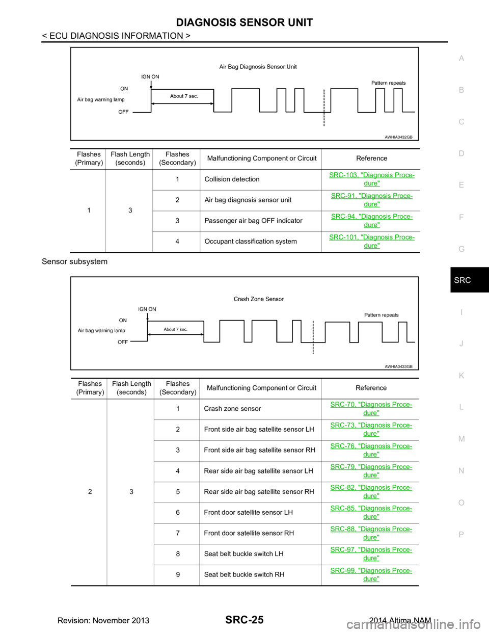
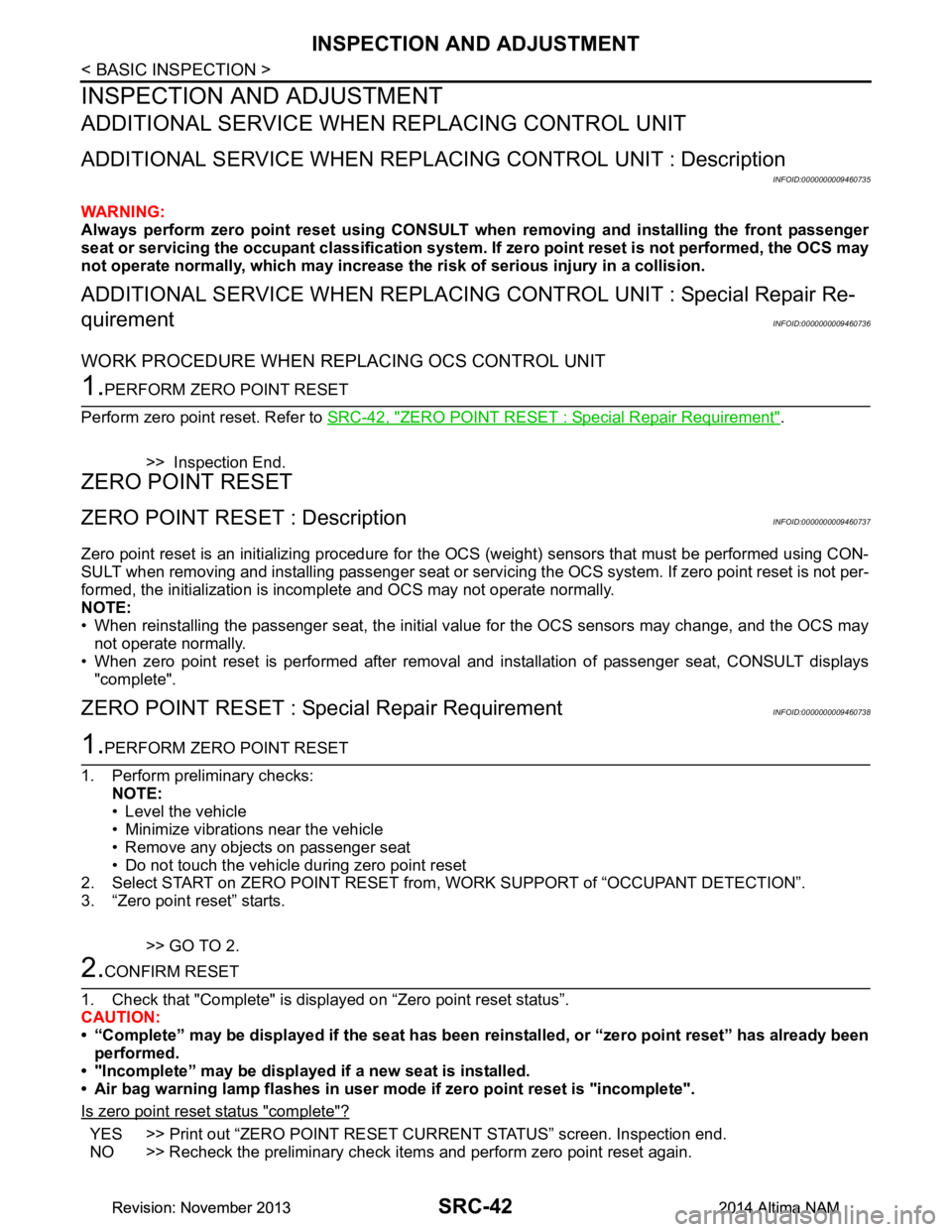
Sensor subsystem
AWHIA0432GB
Flashes
(Primary) Flash Length
(seconds) Flashes
(Secondary) Malfunctioning Component or Circuit Reference
13 1 Collision detection
SRC-103, "Diagnosis Proce-
dure"
2 Air bag diagnosis sensor unit
SRC-91, "Diagnosis Proce-dure"
3 Passenger air bag OFF indicatorSRC-94, "Diagnosis Proce-dure"
4 Occupant classification systemSRC-101, "Diagnosis Proce-dure"
AWHIA0433GB
Flashes
(Primary) Flash Length
(seconds) Flashes
(Secondary) Malfunctioning Component or Circuit Reference
23 1 Crash zone sensor
SRC-70, "Diagnosis Proce-
dure"
2 Front side air bag satellite sensor LHSRC-73, "Diagnosis Proce-dure"
3 Front side air bag satellite sensor RH
SRC-76, "Diagnosis Proce-dure"
4 Rear side air bag satellite sensor LHSRC-79, "Diagnosis Proce-dure"
5 Rear side air bag satellite sensor RHSRC-82, "Diagnosis Proce-dure"
6 Front door satellite sensor LH
SRC-85, "Diagnosis Proce-dure"
7 Front door satellite sensor RHSRC-88, "Diagnosis Proce-dure"
8 Seat belt buckle switch LHSRC-97, "Diagnosis Proce-dure"
9 Seat belt buckle switch RH
SRC-99, "Diagnosis Proce-dure"
Revision: November 20132014 Altima NAMRevision: November 20132014 Altima NAM
Page 4035 of 4801
SRC-42
< BASIC INSPECTION >
INSPECTION AND ADJUSTMENT
INSPECTION AND ADJUSTMENT
ADDITIONAL SERVICE WHEN REPLACING CONTROL UNIT
ADDITIONAL SERVICE WHEN REPL ACING CONTROL UNIT : Description
INFOID:0000000009460735
WARNING:
Always perform zero point reset using CONSULT when removing an d installing the front passenger
seat or servicing the occupant classification system. If zero point reset is not performed, the OCS may
not operate normally, which may increase the risk of serious injury in a collision.
ADDITIONAL SERVICE WHEN REPLACING CONTROL UNIT : Special Repair Re-
quirement
INFOID:0000000009460736
WORK PROCEDURE WHEN REPLACING OCS CONTROL UNIT
1.PERFORM ZERO POINT RESET
Perform zero point reset. Refer to SRC-42, "ZERO POINT RESET : Special Repair Requirement"
.
>> Inspection End.
ZERO POINT RESET
ZERO POINT RESET : DescriptionINFOID:0000000009460737
Zero point reset is an initializing procedure for the OCS (weight) sensors that must be performed using CON-
SULT when removing and installing passenger seat or servic ing the OCS system. If zero point reset is not per-
formed, the initialization is incomplete and OCS may not operate normally.
NOTE:
• When reinstalling the passenger seat, the initial value for the OCS sensors may change, and the OCS may
not operate normally.
• When zero point reset is performed after removal and installation of passenger seat, CONSULT displays "complete".
ZERO POINT RESET : Spec ial Repair RequirementINFOID:0000000009460738
1.PERFORM ZERO POINT RESET
1. Perform preliminary checks: NOTE:
• Level the vehicle
• Minimize vibrations near the vehicle
• Remove any objects on passenger seat
• Do not touch the vehicle during zero point reset
2. Select START on ZERO POINT RESET from , WORK SUPPORT of “OCCUPANT DETECTION”.
3. “Zero point reset” starts.
>> GO TO 2.
2.CONFIRM RESET
1. Check that "Complete" is displayed on “Zero point reset status”.
CAUTION:
• “Complete” may be displayed if the seat has been reinstalled, or “zero point reset” has already been
performed.
• "Incomplete” may be displayed if a new seat is installed.
• Air bag warning lamp flashes in user mode if zero point reset is "incomplete".
Is zero point reset status "complete"?
YES >> Print out “ZERO POINT RESET CURRENT STATUS” screen. Inspection end.
NO >> Recheck the preliminary check items and perform zero point reset again.
Revision: November 20132014 Altima NAMRevision: November 20132014 Altima NAM
Page 4037 of 4801
SRC-44
< DTC/CIRCUIT DIAGNOSIS >
B0001, B0002 DRIVER AIRBAG MODULE
DTC/CIRCUIT DIAGNOSIS
B0001, B0002 DRIVER AIRBAG MODULE
DescriptionINFOID:0000000009460741
DTC B0001, B0002 DRIVER AIRBAG MODULE
The driver air bag module is dual stage and wired to the air bag diagnosis sensor unit through the spiral cable.
The air bag diagnosis sensor unit will monitor for opens and shorts in detected lines to the driver air bag mod-
ule including the spiral cable.
PA R T L O C AT I O N
Refer to SRC-5, "Component Parts Location".
DTC LogicINFOID:0000000009460742
DTC DETECTION LOGIC
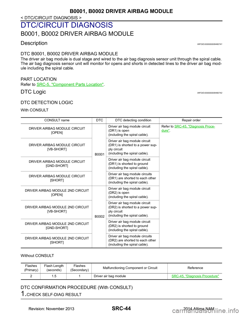
With CONSULT
Without CONSULT
DTC CONFIRMATION PROCEDURE (With CONSULT)
1.CHECK SELF-DIAG RESULT
CONSULT name DTC DTC detect ing condition Repair order
DRIVER AIRBAG MODULE CIRCUIT [OPEN]
B0001Driver air bag module circuit
(DR1) is open
(including the spiral cable). Refer to
SRC-45, "Diagnosis Proce-
dure".
DRIVER AIRBAG MODULE CIRCUIT [VB-SHORT] Driver air bag module circuit
(DR1) is shorted to a power sup-
ply circuit
(including the spiral cable).
DRIVER AIRBAG MODULE CIRCUIT [GND-SHORT] Driver air bag module circuit
(DR1) is shorted to ground
(including the spiral cable).
DRIVER AIRBAG MODULE CIRCUIT [SHORT] Driver air bag module circuits
(DR1) are shorted to each other
(including the spiral cable).
DRIVER AIRBAG MODULE 2ND CIRCUIT [OPEN]
B0002Driver air bag module circuit
(DR2) is open
(including the spiral cable).
DRIVER AIRBAG MODULE 2ND CIRCUIT [VB-SHORT] Driver air bag module circuit
(DR2) is shorted to a power sup-
ply circuit
(including the spiral cable).
DRIVER AIRBAG MODULE 2ND CIRCUIT [GND-SHORT] Driver air bag module circuit
(DR2) is shorted to ground
(including the spiral cable).
DRIVER AIRBAG MODULE 2ND CIRCUIT [SHORT] Driver air bag module circuits
(DR2) are shorted to each other
(including the spiral cable).
Flashes
(Primary) Flash Length
(seconds) Flashes
(Secondary) Malfunctioning Component or Circuit Reference
2 1.5 1 Driver air bag module SRC-45, "Diagnosis Procedure"
Revision: November 20132014 Altima NAMRevision: November 20132014 Altima NAM
Page 4039 of 4801
SRC-46
< DTC/CIRCUIT DIAGNOSIS >
B0001, B0002 DRIVER AIRBAG MODULE
The entire wiring harness should be inspected from the air bag diagnosis sensor unit to the end component
(including any in-line connectors).
Is the inspection result normal?
YES >> GO TO 4
NO >> Replace the harness.
4.CHECK SPIRAL CABLE CIRCUIT
1. Turn ignition switch OFF.
2. Disconnect driver air bag module harness connectors and combination switch (spiral cable) harness con-
nector.
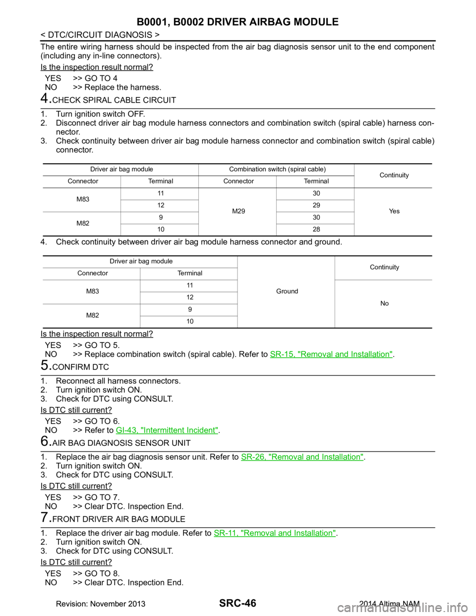
3. Check continuity between driver air bag module har ness connector and combination switch (spiral cable)
connector.
4. Check continuity between driver air bag module harness connector and ground.
Is the inspection result normal?
YES >> GO TO 5.
NO >> Replace combination switch (spiral cable). Refer to SR-15, "Removal and Installation"
.
5.CONFIRM DTC
1. Reconnect all harness connectors.
2. Turn ignition switch ON.
3. Check for DTC using CONSULT.
Is DTC still current?
YES >> GO TO 6.
NO >> Refer to GI-43, "Intermittent Incident"
.
6.AIR BAG DIAGNOSIS SENSOR UNIT
1. Replace the air bag diagnosis sensor unit. Refer to SR-26, "Removal and Installation"
.
2. Turn ignition switch ON.
3. Check for DTC using CONSULT.
Is DTC still current?
YES >> GO TO 7.
NO >> Clear DTC. Inspection End.
7.FRONT DRIVER AIR BAG MODULE
1. Replace the driver air bag module. Refer to SR-11, "Removal and Installation"
.
2. Turn ignition switch ON.
3. Check for DTC using CONSULT.
Is DTC still current?
YES >> GO TO 8.
NO >> Clear DTC. Inspection End.
Driver air bag module Combination switch (spiral cable) Continuity
Connector Terminal Connector Terminal
M83 11
M29 30
Ye s
12 29
M82 930
10 28
Driver air bag module GroundContinuity
Connector Terminal
M83 11
No
12
M82 9
10
Revision: November 20132014 Altima NAMRevision: November 20132014 Altima NAM
Page 4041 of 4801

SRC-48
< DTC/CIRCUIT DIAGNOSIS >
B0010, B0011 PASSENGER AIRBAG MODULE
B0010, B0011 PASSENGER AIRBAG MODULE
DescriptionINFOID:0000000009460744
DTC B0010, B0011 PASSENGER AIR BAG MODULE
The passenger air bag module is dual stage and is wired to the air bag diagnosis sensor unit. The air bag
diagnosis sensor unit will monitor for opens and shorts in detected lines to the passenger air bag module.
PA R T L O C AT I O N
Refer to SRC-5, "Component Parts Location".
DTC LogicINFOID:0000000009460745
DTC DETECTION LOGIC
With CONSULT
Without CONSULT
DTC CONFIRMATION PROCEDURE (With CONSULT)
1.CHECK SELF-DIAG RESULT
1. Turn ignition switch ON.
2. Check for DTC using CONSULT.
Is the DTC detected?
YES (Current DTC)>>Refer to SRC-49, "Diagnosis Procedure".
YES (Past DTC)>>GO TO 2.
NO >> Inspection End.
2.ERASE SELF-DIAG RESULT
Erase the DTC using CONSULT.
Can the DTC be erased?
CONSULT name DTC DTC detecting condition Repair order
ASSIST AIRBAG MODULE CIRCUIT [OPEN]
B0010Front passenger air bag module circuit
(AS1) is open. Refer to
SRC-49, "Diagnosis Proce-
dure".
ASSIST AIRBAG MODULE CIRCUIT [VB-SHORT] Front passenger air bag module circuit
(AS1) is shorted to a power supply cir-
cuit.
ASSIST AIRBAG MODULE CIRCUIT [GND-SHORT] Front passenger air bag module circuit
(AS1) is shorted to ground.
ASSIST AIRBAG MODULE CIRCUIT [SHORT] Front passenger air bag module cir-
cuits (AS1) are shorted to each other.
ASSIST AIRBAG MODULE 2ND CIRCUIT [OPEN]
B0011Front passenger air bag module circuit
(AS2) is open.
ASSIST AIRBAG MODULE 2ND CIRCUIT [VB-SHORT] Front passenger air bag module circuit
(AS2) is shorted to a power supply cir-
cuit.
ASSIST AIRBAG MODULE 2ND CIRCUIT [GND-SHORT] Front passenger air bag module circuit
(AS2) is shorted to ground.
ASSIST AIRBAG MODULE 2ND CIRCUIT [SHORT] Front passenger air bag module cir-
cuits (AS2) are shorted to each other.
Flashes
(Primary) Flash Length
(seconds) Flashes
(Secondary) Malfunctioning Component or Circuit Reference
2 1.5 2 Passenger air bag module SRC-49, "Diagnosis Procedure"
Revision: November 20132014 Altima NAMRevision: November 20132014 Altima NAM
Page 4042 of 4801
B0010, B0011 PASSENGER AIRBAG MODULESRC-49
< DTC/CIRCUIT DIAGNOSIS >
C
D E
F
G
I
J
K L
M A
B
SRC
N
O P
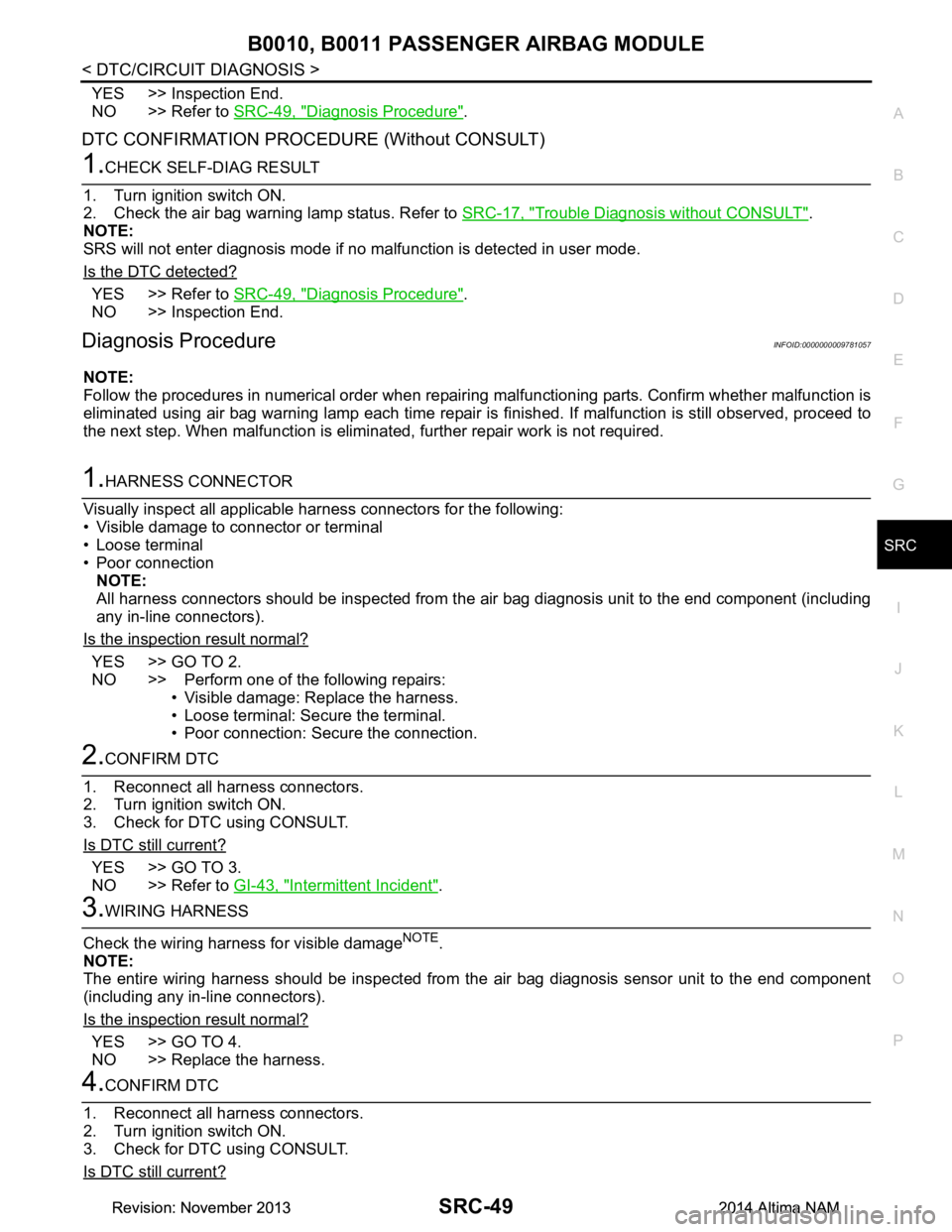
YES >> Inspection End.
NO >> Refer to SRC-49, "Diagnosis Procedure"
.
DTC CONFIRMATION PROCEDURE (Without CONSULT)
1.CHECK SELF-DIAG RESULT
1. Turn ignition switch ON.
2. Check the air bag warning lamp status. Refer to SRC-17, "Trouble Diagnosis without CONSULT"
.
NOTE:
SRS will not enter diagnosis mode if no malfunction is detected in user mode.
Is the DTC detected?
YES >> Refer to SRC-49, "Diagnosis Procedure".
NO >> Inspection End.
Diagnosis ProcedureINFOID:0000000009781057
NOTE:
Follow the procedures in numerical order when repairi ng malfunctioning parts. Confirm whether malfunction is
eliminated using air bag warning lamp each time repair is finished. If malfunction is still observed, proceed to
the next step. When malfunction is eliminated, further repair work is not required.
1.HARNESS CONNECTOR
Visually inspect all applicable harness connectors for the following:
• Visible damage to connector or terminal
• Loose terminal
• Poor connection
NOTE:
All harness connectors should be inspected from the air bag diagnosis unit to the end component (including
any in-line connectors).
Is the inspection result normal?
YES >> GO TO 2.
NO >> Perform one of the following repairs:
• Visible damage: Replace the harness.
• Loose terminal: Secure the terminal.
• Poor connection: Secure the connection.
2.CONFIRM DTC
1. Reconnect all harness connectors.
2. Turn ignition switch ON.
3. Check for DTC using CONSULT.
Is DTC still current?
YES >> GO TO 3.
NO >> Refer to GI-43, "Intermittent Incident"
.
3.WIRING HARNESS
Check the wiring harness for visible damage
NOTE.
NOTE:
The entire wiring harness should be inspected from the air bag diagnosis sensor unit to the end component
(including any in-line connectors).
Is the inspection result normal?
YES >> GO TO 4.
NO >> Replace the harness.
4.CONFIRM DTC
1. Reconnect all harness connectors.
2. Turn ignition switch ON.
3. Check for DTC using CONSULT.
Is DTC still current?
Revision: November 20132014 Altima NAMRevision: November 20132014 Altima NAM
Page 4043 of 4801

SRC-50
< DTC/CIRCUIT DIAGNOSIS >
B0010, B0011 PASSENGER AIRBAG MODULE
YES >> GO TO 5.
NO >> Refer to GI-43, "Intermittent Incident"
.
5.AIR BAG DIAGNOSIS SENSOR UNIT
1. Replace the air bag diagnosis sensor unit. Refer to SR-26, "Removal and Installation"
.
2. Turn ignition switch ON.
3. Check for DTC using CONSULT.
Is DTC still current?
YES >> GO TO 6.
NO >> Clear DTC. Inspection End.
6.FRONT PASSENGER AIR BAG MODULE
1. Replace the front passenger air bag module. Refer to SR-17, "Removal and Installation"
.
2. Turn ignition switch ON.
3. Check for DTC using CONSULT.
Is DTC still current?
YES >> GO TO 7.
NO >> Clear DTC. Inspection End.
7.RELATED HARNESS
Replace the related harness.
>>END
Revision: November 20132014 Altima NAMRevision: November 20132014 Altima NAM
Page 4044 of 4801
B0020 SIDE AIRBAG MODULE LHSRC-51
< DTC/CIRCUIT DIAGNOSIS >
C
D E
F
G
I
J
K L
M A
B
SRC
N
O P
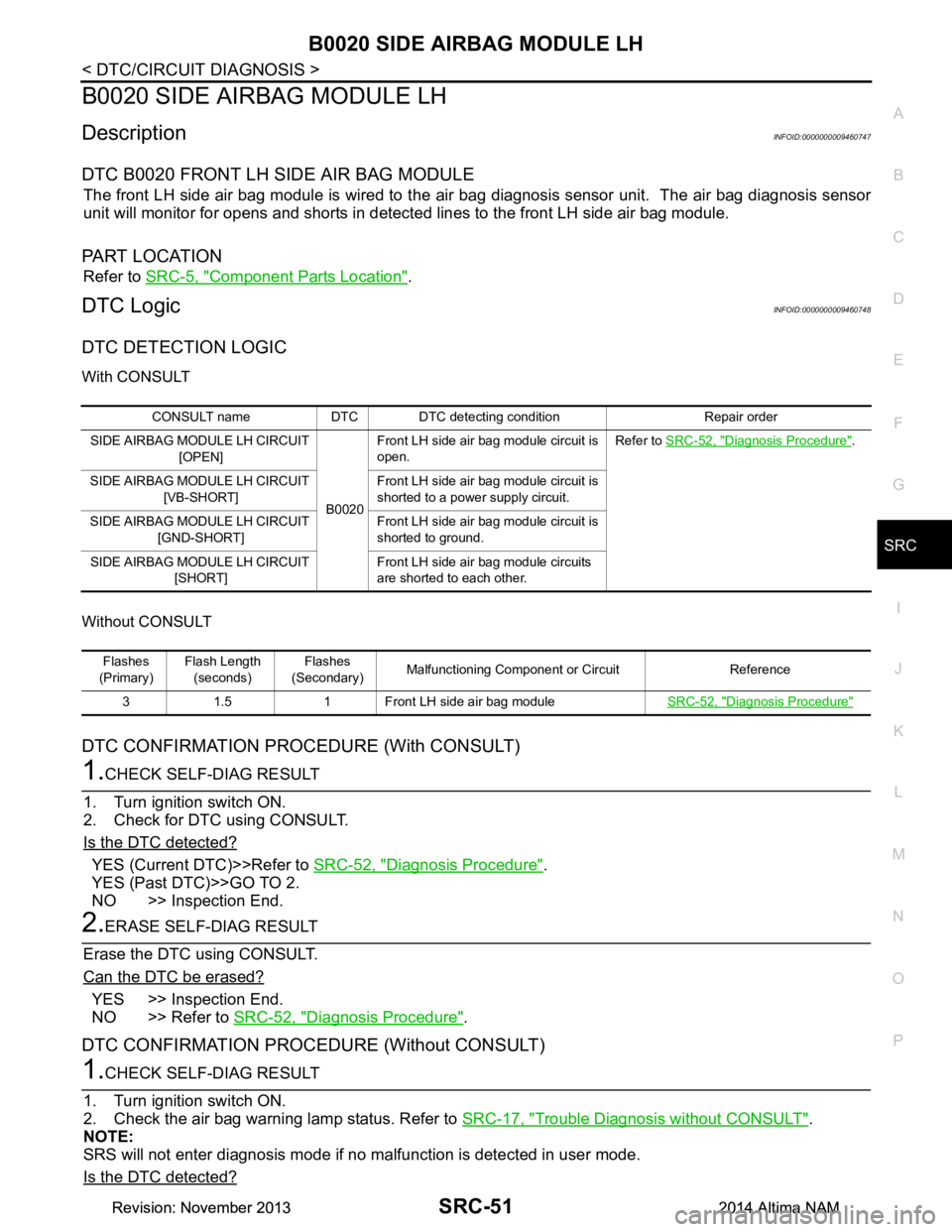
B0020 SIDE AIRBAG MODULE LH
DescriptionINFOID:0000000009460747
DTC B0020 FRONT LH SIDE AIR BAG MODULE
The front LH side air bag module is wired to the air bag diagnosis sensor unit. The air bag diagnosis sensor
unit will monitor for opens and shorts in detected lines to the front LH side air bag module.
PA R T L O C AT I O N
Refer to SRC-5, "Component Parts Location".
DTC LogicINFOID:0000000009460748
DTC DETECTION LOGIC
With CONSULT
Without CONSULT
DTC CONFIRMATION PROCEDURE (With CONSULT)
1.CHECK SELF-DIAG RESULT
1. Turn ignition switch ON.
2. Check for DTC using CONSULT.
Is the DTC detected?
YES (Current DTC)>>Refer to SRC-52, "Diagnosis Procedure".
YES (Past DTC)>>GO TO 2.
NO >> Inspection End.
2.ERASE SELF-DIAG RESULT
Erase the DTC using CONSULT.
Can the DTC be erased?
YES >> Inspection End.
NO >> Refer to SRC-52, "Diagnosis Procedure"
.
DTC CONFIRMATION PROCEDURE (Without CONSULT)
1.CHECK SELF-DIAG RESULT
1. Turn ignition switch ON.
2. Check the air bag warning lamp status. Refer to SRC-17, "Trouble Diagnosis without CONSULT"
.
NOTE:
SRS will not enter diagnosis mode if no malfunction is detected in user mode.
Is the DTC detected?
CONSULT name DTC DTC detecting condition Repair order
SIDE AIRBAG MODULE LH CIRCUIT [OPEN]
B0020Front LH side air bag module circuit is
open. Refer to
SRC-52, "Diagnosis Procedure"
.
SIDE AIRBAG MODULE LH CIRCUIT [VB-SHORT] Front LH side air bag module circuit is
shorted to a power supply circuit.
SIDE AIRBAG MODULE LH CIRCUIT [GND-SHORT] Front LH side air bag module circuit is
shorted to ground.
SIDE AIRBAG MODULE LH CIRCUIT [SHORT] Front LH side air bag module circuits
are shorted to each other.
Flashes
(Primary) Flash Length
(seconds) Flashes
(Secondary) Malfunctioning Component or Circuit Reference
3 1.5 1 Front LH side air bag module SRC-52, "Diagnosis Procedure"
Revision: November 20132014 Altima NAMRevision: November 20132014 Altima NAM