2014 NISSAN TEANA battery
[x] Cancel search: batteryPage 4164 of 4801
POWER STEERING CONTROL MODULESTC-13
< ECU DIAGNOSIS INFORMATION >
C
D E
F
H I
J
K L
M A
B
STC
N
O P
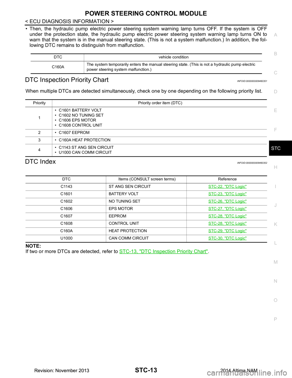
• Then, the hydraulic pump electric power steering syste m warning lamp turns OFF. If the system is OFF
under the protection state, the hydraulic pump electr ic power steering system warning lamp turns ON to
warn that the system is in the manual steering state. (This is not a system malfunction.) In addition, the fol-
lowing DTC remains to distinguish from malfunction.
DTC Inspection Priority ChartINFOID:0000000009460351
When multiple DTCs are detected simultaneously, c heck one by one depending on the following priority list.
DTC IndexINFOID:0000000009460352
NOTE:
If two or more DTCs are detected, refer to STC-13, "DTC Inspection Priority Chart"
.
DTC vehicle condition
C160A The system temporarily enters the manual steering state. (This is not a hydraulic pump electric
power steering system malfunction.)
Priority Priority order item (DTC)
1 • C1601 BATTERY VOLT
• C1602 NO TUNING SET
• C1606 EPS MOTOR
• C1608 CONTROL UNIT
2 • C1607 EEPROM
3 • C160A HEAT PROTECTION
4 • C1143 ST ANG SEN CIRCUIT
• U1000 CAN COMM CIRCUIT
DTC Items (CONSULT screen terms) Reference
C1143 ST ANG SEN CIRCUIT STC-22, "DTC Logic"
C1601 BATTERY VOLT STC-23, "DTC Logic"
C1602 NO TUNING SETSTC-26, "DTC Logic"
C1606 EPS MOTORSTC-27, "DTC Logic"
C1607 EEPROMSTC-28, "DTC Logic"
C1608 CONTROL UNITSTC-28, "DTC Logic"
C160A HEAT PROTECTION STC-29, "DTC Logic"
U1000 CAN COMM CIRCUITSTC-30, "DTC Logic"
Revision: November 20132014 Altima NAMRevision: November 20132014 Altima NAM
Page 4174 of 4801
C1601 BATTERY POWER SUPPLYSTC-23
< DTC/CIRCUIT DIAGNOSIS >
C
D E
F
H I
J
K L
M A
B
STC
N
O P
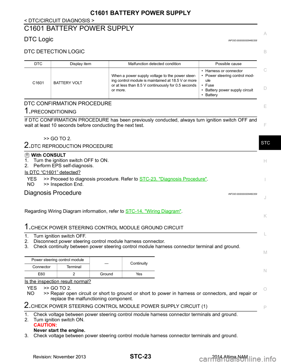
C1601 BATTERY POWER SUPPLY
DTC LogicINFOID:0000000009460358
DTC DETECTION LOGIC
DTC CONFIRMATION PROCEDURE
1.PRECONDITIONING
If DTC CONFIRMATION PROCEDURE has been previously conducted, always turn ignition switch OFF and
wait at least 10 seconds before conducting the next test.
>> GO TO 2.
2.DTC REPRODUCTION PROCEDURE
With CONSULT
1. Turn the ignition switch OFF to ON.
2. Perform EPS self-diagnosis.
Is DTC
“C1601” detected?
YES >> Proceed to diagnosis procedure. Refer to STC-23, "Diagnosis Procedure".
NO >> Inspection End.
Diagnosis ProcedureINFOID:0000000009460359
Regarding Wiring Diagram information, refer to STC-14, "Wiring Diagram".
1.CHECK POWER STEERING CONTROL MODULE GROUND CIRCUIT
1. Turn ignition switch OFF.
2. Disconnect power steering control module harness connector.
3. Check continuity between power steering control module harness connector terminal and ground.
Is the inspection result normal?
YES >> GO TO 2.
NO >> Repair open circuit or short to ground or short to power in harness or connectors, and repair or
replace the malfunctioning component.
2.CHECK POWER STEERING CONTROL MO DULE POWER SUPPLY CIRCUIT (1)
1. Check voltage between power steering control module harness connector terminals and ground.
2. Turn ignition switch ON. CAUTION:
Never start the engine.
3. Check voltage between power steering control module harness connector terminals and ground.
DTC Display item Malfunction detected condition Possible cause
C1601 BATTERY VOLT When a power supply voltage to the power steer-
ing control module is maintained at 18.5 V or more
or at less than 8.5 V continuously for 0.5 seconds
or more. • Harness or connector
• Power steering control mod-
ule
•Fuse
• Battery power supply circuit
•Battery
Power steering control module
—Continuity
Connector Terminal
E60 2 Ground Yes
Revision: November 20132014 Altima NAMRevision: November 20132014 Altima NAM
Page 4175 of 4801
STC-24
< DTC/CIRCUIT DIAGNOSIS >
C1601 BATTERY POWER SUPPLY
Is the inspection result normal?
YES >> GO TO 4.
NO >> GO TO 3.
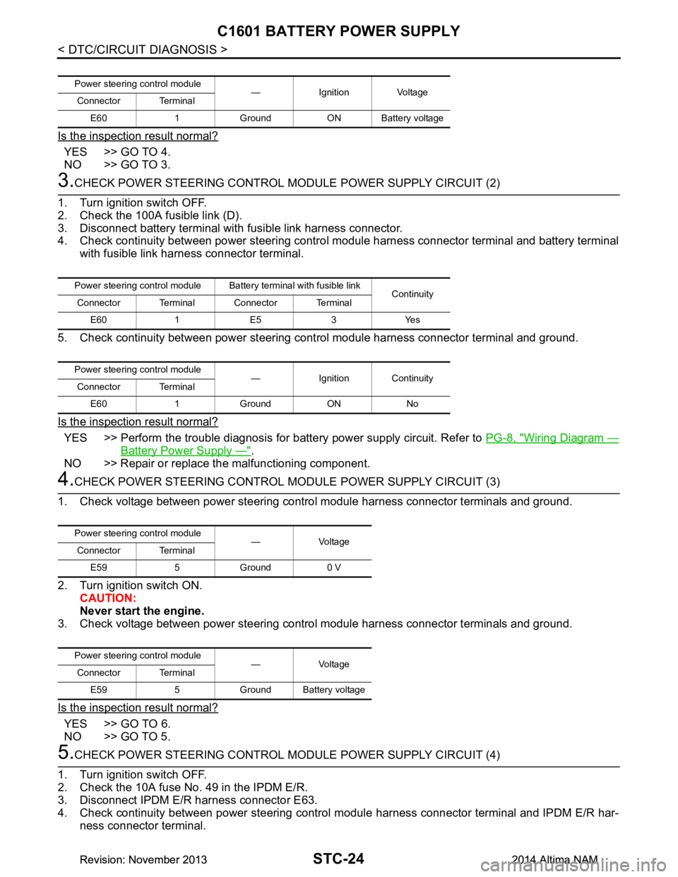
3.CHECK POWER STEERING CONTROL MODULE POWER SUPPLY CIRCUIT (2)
1. Turn ignition switch OFF.
2. Check the 100A fusible link (D).
3. Disconnect battery terminal with fusible link harness connector.
4. Check continuity between power steering contro l module harness connector terminal and battery terminal
with fusible link harness connector terminal.
5. Check continuity between power steering c ontrol module harness connector terminal and ground.
Is the inspection result normal?
YES >> Perform the trouble diagnosis for battery power supply circuit. Refer to PG-8, "Wiring Diagram —
Battery Power Supply —".
NO >> Repair or replace the malfunctioning component.
4.CHECK POWER STEERING CONTROL MODULE POWER SUPPLY CIRCUIT (3)
1. Check voltage between power steering control module harness connector terminals and ground.
2. Turn ignition switch ON. CAUTION:
Never start the engine.
3. Check voltage between power steering control module harness connector terminals and ground.
Is the inspection result normal?
YES >> GO TO 6.
NO >> GO TO 5.
5.CHECK POWER STEERING CONTROL MODULE POWER SUPPLY CIRCUIT (4)
1. Turn ignition switch OFF.
2. Check the 10A fuse No. 49 in the IPDM E/R.
3. Disconnect IPDM E/R harness connector E63.
4. Check continuity between power steering control module harness connector terminal and IPDM E/R har-
ness connector terminal.
Power steering control module — Ignition Voltage
Connector Terminal
E60 1 Ground ON Battery voltage
Power steering control module Batte ry terminal with fusible link
Continuity
Connector Terminal Connector Terminal
E60 1 E5 3 Yes
Power steering control module — Ignition Continuity
Connector Terminal
E60 1 Ground ON No
Power steering control module —Voltage
Connector Terminal
E59 5 Ground 0 V
Power steering control module —Voltage
Connector Terminal
E59 5 Ground Battery voltage
Revision: November 20132014 Altima NAMRevision: November 20132014 Altima NAM
Page 4176 of 4801
C1601 BATTERY POWER SUPPLYSTC-25
< DTC/CIRCUIT DIAGNOSIS >
C
D E
F
H I
J
K L
M A
B
STC
N
O P
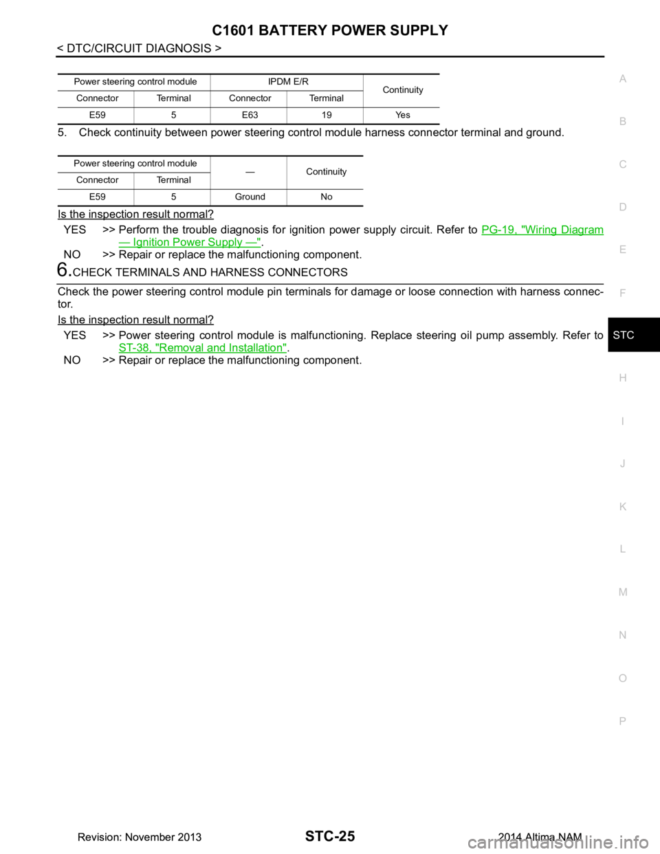
5. Check continuity between power steering control module harness connector terminal and ground.
Is the inspection result normal?
YES >> Perform the trouble diagnosis for i gnition power supply circuit. Refer to PG-19, "Wiring Diagram
— Ignition Power Supply —".
NO >> Repair or replace the malfunctioning component.
6.CHECK TERMINALS AND HARNESS CONNECTORS
Check the power steering control module pin terminal s for damage or loose connection with harness connec-
tor.
Is the inspection result normal?
YES >> Power steering control module is malfunctioni ng. Replace steering oil pump assembly. Refer to
ST-38, "Removal and Installation"
.
NO >> Repair or replace the malfunctioning component.
Power steering cont rol module IPDM E/R
Continuity
Connector Terminal Connector Terminal
E59 5 E63 19 Yes
Power steering control module
—Continuity
Connector Terminal
E59 5 Ground No
Revision: November 20132014 Altima NAMRevision: November 20132014 Altima NAM
Page 4185 of 4801
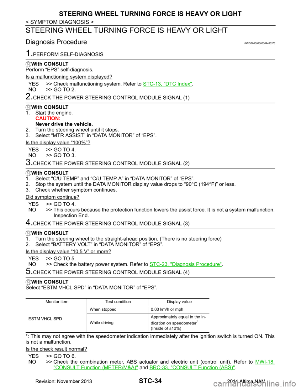
STC-34
< SYMPTOM DIAGNOSIS >
STEERING WHEEL TURNING FORCE IS HEAVY OR LIGHT
STEERING WHEEL TURNING FORCE IS HEAVY OR LIGHT
Diagnosis ProcedureINFOID:0000000009460376
1.PERFORM SELF-DIAGNOSIS
With CONSULT
Perform “EPS” self-diagnosis.
Is a malfunctioning system displayed?
YES >> Check malfunctioning system. Refer to STC-13, "DTC Index".
NO >> GO TO 2.
2.CHECK THE POWER STEERING CONTROL MODULE SIGNAL (1)
With CONSULT
1. Start the engine. CAUTION:
Never drive the vehicle.
2. Turn the steering wheel until it stops.
3. Select “MTR ASSIST” in “DATA MONITOR” of “EPS”.
Is the display value
“100%”?
YES >> GO TO 4.
NO >> GO TO 3.
3.CHECK THE POWER STEERING CONTROL MODULE SIGNAL (2)
With CONSULT
1. Select “C/U TEMP” and “C/U TEMP A” in “DATA MONITOR” of “EPS”.
2. Stop the system until the DATA MONITOR display value drops to “90 °C (194 °F)” or less.
3. Check whether symptom continues.
Did symptom continue?
YES >> GO TO 4.
NO >> This occurs because the protection function lowers the assist force. It is not a system malfunction.
Inspection End.
4.CHECK THE POWER STEERING CONTROL MODULE SIGNAL (3)
With CONSULT
1. Turn the steering wheel to the straight -ahead position. (There is no steering force)
2. Select “BATTERY VOLT” in “DATA MONITOR” of “EPS”.
Is the display value
“10.5 V” or more?
YES >> GO TO 5.
NO >> Check the battery power system. Refer to STC-23, "Diagnosis Procedure"
.
5.CHECK THE POWER STEERING CONTROL MODULE SIGNAL (4)
With CONSULT
Select “ESTM VHCL SPD” in “DATA MONITOR” of “EPS”.
*: This may not agree with the speedometer indication imm ediately after the ignition switch is turned ON. This
is not a malfunction.
Is the check result normal?
YES >> GO TO 6.
NO >> Check the combination meter, ABS actuator and electric unit (control unit). Refer to MWI-18,
"CONSULT Function (METER/M&A)" and BRC-33, "CONSULT Function (ABS)".
Monitor item Test condition Display value
ESTM VHCL SPD When stopped 0.00 km/h or mph
While driving Approximately equal to the in-
dication on speedometer
*
(Inside of ±10%)
Revision: November 20132014 Altima NAMRevision: November 20132014 Altima NAM
Page 4188 of 4801
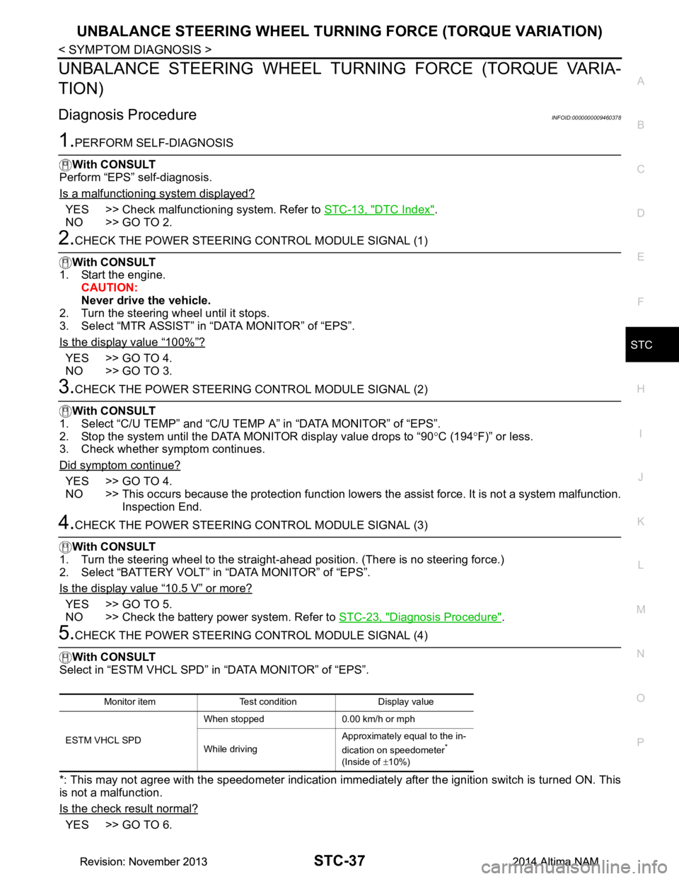
UNBALANCE STEERING WHEEL TURNING FORCE (TORQUE VARIATION)
STC-37
< SYMPTOM DIAGNOSIS >
C
D E
F
H I
J
K L
M A
B
STC
N
O P
UNBALANCE STEERING WHEEL TU RNING FORCE (TORQUE VARIA-
TION)
Diagnosis ProcedureINFOID:0000000009460378
1.PERFORM SELF-DIAGNOSIS
With CONSULT
Perform “EPS” self-diagnosis.
Is a malfunctioning system displayed?
YES >> Check malfunctioning system. Refer to STC-13, "DTC Index".
NO >> GO TO 2.
2.CHECK THE POWER STEERING CONTROL MODULE SIGNAL (1)
With CONSULT
1. Start the engine. CAUTION:
Never drive the vehicle.
2. Turn the steering wheel until it stops.
3. Select “MTR ASSIST” in “DATA MONITOR” of “EPS”.
Is the display value
“100%”?
YES >> GO TO 4.
NO >> GO TO 3.
3.CHECK THE POWER STEERING CONTROL MODULE SIGNAL (2)
With CONSULT
1. Select “C/U TEMP” and “C/U TEMP A” in “DATA MONITOR” of “EPS”.
2. Stop the system until the DATA MONITOR display value drops to “90 °C (194 °F)” or less.
3. Check whether symptom continues.
Did symptom continue?
YES >> GO TO 4.
NO >> This occurs because the protection function lowers the assist force. It is not a system malfunction.
Inspection End.
4.CHECK THE POWER STEERING CONTROL MODULE SIGNAL (3)
With CONSULT
1. Turn the steering wheel to the straight -ahead position. (There is no steering force.)
2. Select “BATTERY VOLT” in “DATA MONITOR” of “EPS”.
Is the display value
“10.5 V” or more?
YES >> GO TO 5.
NO >> Check the battery power system. Refer to STC-23, "Diagnosis Procedure"
.
5.CHECK THE POWER STEERING CONTROL MODULE SIGNAL (4)
With CONSULT
Select in “ESTM VHCL SPD” in “DATA MONITOR” of “EPS”.
*: This may not agree with the speedometer indication immediately after the ignition switch is turned ON. This
is not a malfunction.
Is the check result normal?
YES >> GO TO 6.
Monitor item Test condition Display value
ESTM VHCL SPD When stopped 0.00 km/h or mph
While driving Approximately equal to the in-
dication on speedometer
*
(Inside of ±10%)
Revision: November 20132014 Altima NAMRevision: November 20132014 Altima NAM
Page 4190 of 4801
POWER STEERING CONTROL MODULESTC-39
< UNIT REMOVAL AND INSTALLATION >
C
D E
F
H I
J
K L
M A
B
STC
N
O P
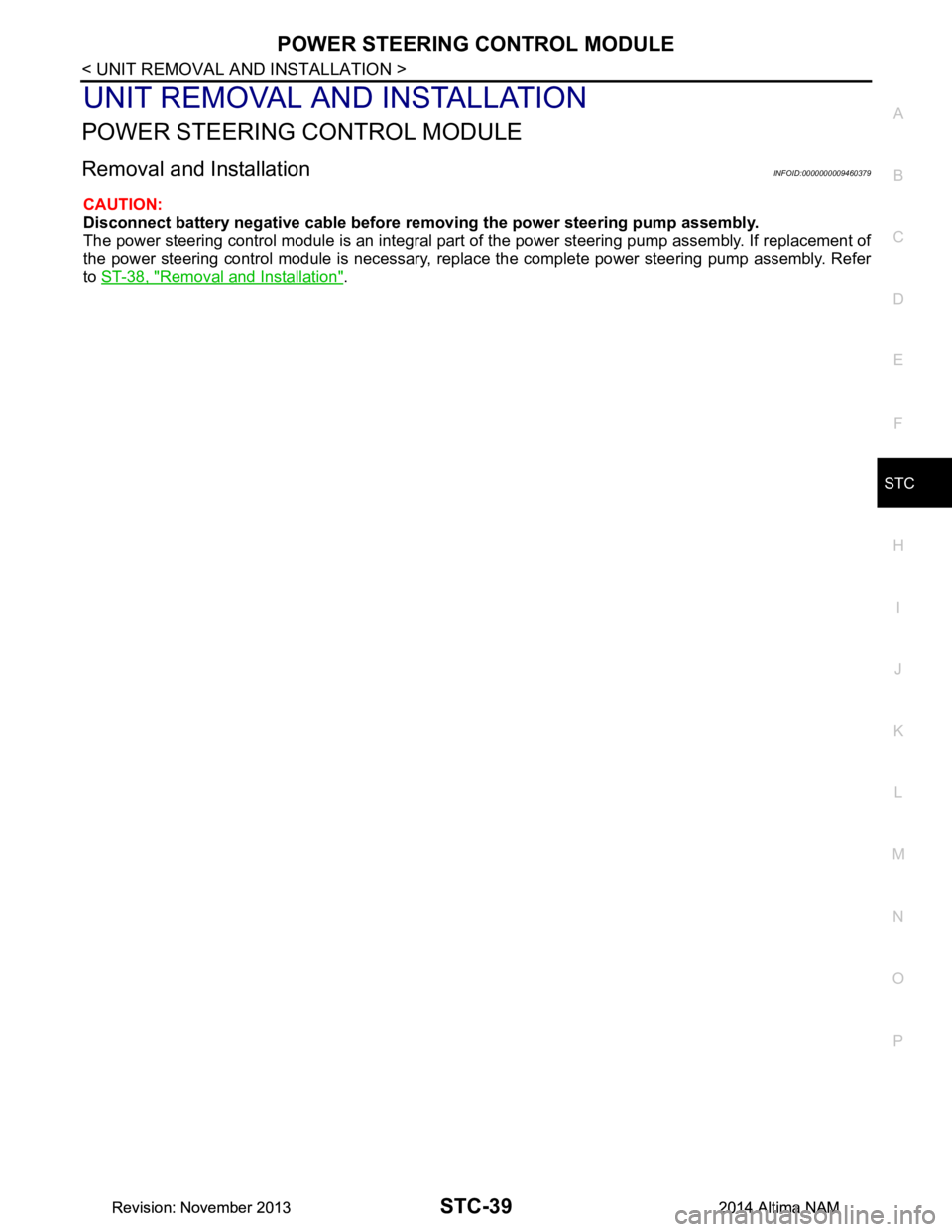
UNIT REMOVAL AND INSTALLATION
POWER STEERING CONTROL MODULE
Removal and InstallationINFOID:0000000009460379
CAUTION:
Disconnect battery negative cable before removing the power steering pump assembly.
The power steering control module is an integral part of the power steering pump assembly. If replacement of
the power steering control module is necessary, replac e the complete power steering pump assembly. Refer
to ST-38, "Removal and Installation"
.
Revision: November 20132014 Altima NAMRevision: November 20132014 Altima NAM
Page 4192 of 4801

STR-2
< PRECAUTION >
PRECAUTIONS
PRECAUTION
PRECAUTIONS
Precaution for Supplemental Restraint System (SRS) "AIR BAG" and "SEAT BELT
PRE-TENSIONER"
INFOID:0000000009951694
The Supplemental Restraint System such as “A IR BAG” and “SEAT BELT PRE-TENSIONER”, used along
with a front seat belt, helps to reduce the risk or severi ty of injury to the driver and front passenger for certain
types of collision. Information necessary to service the system safely is included in the SR and SB section of
this Service Manual.
WARNING:
• To avoid rendering the SRS inopera tive, which could increase the risk of personal injury or death in
the event of a collision which would result in air bag inflation, all maintenance must be performed by
an authorized NISS AN/INFINITI dealer.
• Improper maintenance, including in correct removal and installation of the SRS, can lead to personal
injury caused by unintent ional activation of the system. For re moval of Spiral Cable and Air Bag
Module, see the SR section.
• Do not use electrical test equipmen t on any circuit related to the SRS unless instructed to in this
Service Manual. SRS wiring harn esses can be identified by yellow and/or orange harnesses or har-
ness connectors.
PRECAUTIONS WHEN USING POWER TOOLS (AIR OR ELECTRIC) AND HAMMERS
WARNING:
• When working near the Airbag Diagnosis Sensor Unit or other Airbag System sensors with the Igni-
tion ON or engine running, DO NOT use air or electri c power tools or strike near the sensor(s) with a
hammer. Heavy vibration could activate the sensor( s) and deploy the air bag(s), possibly causing
serious injury.
• When using air or electric power tools or hammers , always switch the Ignition OFF, disconnect the
battery and wait at least three minutes before performing any service.
Revision: November 20132014 Altima NAMRevision: November 20132014 Altima NAM