Page 4193 of 4801
PREPARATIONSTR-3
< PREPARATION >
C
D E
F
G H
I
J
K L
M A
STR
NP
O
PREPARATION
PREPARATION
Special Service ToolINFOID:0000000009461217
The actual shapes of the tools may differ from those illustrated here.
Commercial Service ToolINFOID:0000000009461218
Tool number
(TechMate No.)
Tool name Description
—
(—) Model GR8-1200 NI
Multitasking battery and electrical diag-
nostic station Tests batteries, starting and charging
systems and charges batteries.
For operating instruct ions, refer to diag-
nostic station instruction manual.
AWIIA1239ZZ
Tool name Description
Power tool Loosening nuts, screws and bolts
PIIB1407E
Revision: November 20132014 Altima NAMRevision: November 20132014 Altima NAM
Page 4194 of 4801
STR-4
< SYSTEM DESCRIPTION >
COMPONENT PARTS
SYSTEM DESCRIPTION
COMPONENT PARTS
QR25DE
QR25DE : Component Parts LocationINFOID:0000000009461219
QR25DE : Component DescriptionINFOID:0000000009461220
VQ35DE
1. Transmission range switch 2. Starter motor 3. IPDM E/R
4. BCM (view with combination meter re- moved)
AWBIA1287ZZ
Component part Description
Transmission range switch Transmission range switch supplies power to the starter relay and
starter control relay inside the IPDM E/R when the shift selector is
placed in the P or N position.
BCM BCM controls the starter relay inside IPDM E/R.
IPDM E/R CPU inside IPDM E/R operates the starter relay when the ignition
switch is in the start position.
Starter motor The starter motor plunger closes and the motor is supplied with
battery power, which in turn cranks the engine, when the S termi-
nal is supplied with electric power.
Revision: November 20132014 Altima NAMRevision: November 20132014 Altima NAM
Page 4195 of 4801
COMPONENT PARTSSTR-5
< SYSTEM DESCRIPTION >
C
D E
F
G H
I
J
K L
M A
STR
NP
O
VQ35DE : Component Parts LocationINFOID:0000000009461221
VQ35DE : Component DescriptionINFOID:0000000009461222
Vehicle front
1. Starter motor 2. Transmission range switch 3. IPDM E/R
4. BCM (view combination meter re- moved)
AWBIA1288ZZ
Component part Description
Transmission range switch Transmission range switch supplies power to the starter relay and
starter control relay inside the IPDM E/R when the shift selector is
placed in the P or N position.
BCM BCM controls the starter relay inside IPDM E/R.
IPDM E/R CPU inside IPDM E/R operates the starter relay when the ignition
switch is in the start position.
Starter motor The starter motor plunger closes and the motor is supplied with
battery power, which in turn cranks the engine, when the S termi-
nal is supplied with electric power.
Revision: November 20132014 Altima NAMRevision: November 20132014 Altima NAM
Page 4196 of 4801

STR-6
< SYSTEM DESCRIPTION >
SYSTEM
SYSTEM
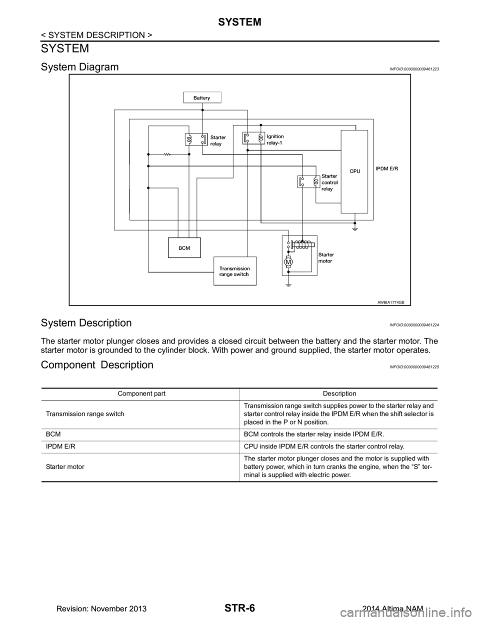
System DiagramINFOID:0000000009461223
System DescriptionINFOID:0000000009461224
The starter motor plunger closes and provides a closed circuit between the battery and the starter motor. The
starter motor is grounded to the cylinder block. With power and ground supplied, the starter motor operates.
Component DescriptionINFOID:0000000009461225
AWBIA1774GB
Component part Description
Transmission range switch Transmission range switch supplies power to the starter relay and
starter control relay inside the IPDM E/R when the shift selector is
placed in the P or N position.
BCM BCM controls the starter relay inside IPDM E/R.
IPDM E/R CPU inside IPDM E/R controls the starter control relay.
Starter motor The starter motor plunger closes and the motor is supplied with
battery power, which in turn cranks the engine, when the “S” ter-
minal is supplied with electric power.
Revision: November 20132014 Altima NAMRevision: November 20132014 Altima NAM
Page 4202 of 4801
STR-12
< BASIC INSPECTION >
DIAGNOSIS AND REPAIR WORKFLOW
BASIC INSPECTION
DIAGNOSIS AND REPAIR WORKFLOW
Work Flow (With GR8-1200 NI)INFOID:0000000009461227
STARTING SYSTEM DIAGNOSIS WITH GR8-1200 NI
To test the starting system, use the following special service tool:
• GR8-1200 NI Multitasking battery and electrical diagnostic station
NOTE:
Refer to the diagnostic station Instruction Manual for proper starting system diagnosis procedures.
Revision: November 20132014 Altima NAMRevision: November 20132014 Altima NAM
Page 4203 of 4801
DIAGNOSIS AND REPAIR WORKFLOWSTR-13
< BASIC INSPECTION >
C
D E
F
G H
I
J
K L
M A
STR
NP
O
OVERALL SEQUENCE
DETAILED FLOW
NOTE:
To ensure a complete and thorough diagnosis, the battery , starter motor and generator test segments must be
done as a set from start to finish.
1.DIAGNOSIS WITH MULTITASKING BATTERY AND ELECTRICAL DIAGNOSTIC STATION GR8-1200 NI
AWBIA1200GB
Revision: November 20132014 Altima NAMRevision: November 20132014 Altima NAM
Page 4204 of 4801

STR-14
< BASIC INSPECTION >
DIAGNOSIS AND REPAIR WORKFLOW
Perform the starting system test with Multitasking battery and electrical diagnostic station GR8-1200 NI. For
details and operating instructions, refer to diagnostic station Instruction Manual.
Te s t r e s u l t
CRANKING NORMAL>>GO TO 2.
LOW VOLTAGE>>GO TO 5.
CHARGE BATTERY>>Perform the slow battery charging procedure. (Initial rate of charge is 10A for 12
hours.) Perform battery test again. Refer to diagnostic station instruction manual.
REPLACE BATTERY>>Before replacing battery, clean t he battery cable clamps and battery posts. Perform
battery test again. Refer to diagnostic station instruction manual. If second test result is
“REPLACE BATTERY”, then do so. Perform battery test again to confirm repair.
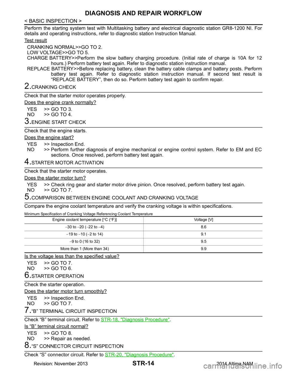
2.CRANKING CHECK
Check that the starter motor operates properly.
Does the engine crank normally?
YES >> GO TO 3.
NO >> GO TO 4.
3.ENGINE START CHECK
Check that the engine starts.
Does the engine start?
YES >> Inspection End.
NO >> Perform further diagnosis of engine mechanical or engine control system. Refer to EM and EC sections. Once resolved, perform battery test again.
4.STARTER MOTOR ACTIVATION
Check that the starter motor operates.
Does the starter motor turn?
YES >> Check ring gear and starter motor drive pinion. Once resolved, perform battery test again.
NO >> GO TO 7.
5.COMPARISON BETWEEN ENGINE COOLANT AND CRANKING VOLTAGE
Compare the engine coolant temperature and verify the cranking voltage is within specifications.
Minimum Specification of Cranking Voltage Referencing Coolant Temperature
Is the voltage less than the specified value?
YES >> GO TO 7.
NO >> GO TO 6.
6.STARTER OPERATION
Check the starter operation.
Does the starter motor turn smoothly?
YES >> Inspection End.
NO >> GO TO 7.
7.“B” TERMINAL CIRCUIT INSPECTION
Check “B” terminal circuit. Refer to STR-18, "Diagnosis Procedure"
.
Is
“B” terminal circuit normal?
YES >> GO TO 8.
NO >> Repair as needed.
8.“S” CONNECTOR CIRCUIT INSPECTION
Check “S” connector circuit. Refer to STR-20, "Diagnosis Procedure"
.
Engine coolant temperature [°C ( °F)] Voltage [V]
− 30 to −20 ( −22 to −4) 8.6
− 19 to −10 ( −2 to 14) 9.1
− 9 to 0 (16 to 32) 9.5
More than 1 (More than 34) 9.9
Revision: November 20132014 Altima NAMRevision: November 20132014 Altima NAM
Page 4205 of 4801
DIAGNOSIS AND REPAIR WORKFLOWSTR-15
< BASIC INSPECTION >
C
D E
F
G H
I
J
K L
M A
STR
NP
O
Is “S” connector circuit normal?
YES >> GO TO 9.
NO >> Repair as needed.
9.ENGINE ROTATION STATUS
Check that the engine can be rotated by hand.
Does the engine turn freely by hand?
YES >> Replace starter motor.
NO >> Perform further diagnosis of engine mechanical or powertrain mechanism. Once resolved, per- form battery test again using Multitasking batte ry and electrical diagnostic station GR8-1200 NI.
Refer to the diagnostic station Instruction Manual for proper testing procedures.
Revision: November 20132014 Altima NAMRevision: November 20132014 Altima NAM