Page 2514 of 4801
TRANSVERSE LINKFSU-13
< REMOVAL AND INSTALLATION >
C
D
F
G H
I
J
K L
M A
B
FSU
N
O P
- If axial end play exceeds the standard value, replace transverse link.
INSTALLATION
Installation is in the reverse order of removal.
• Perform final tightening of bolts and nuts at the front suspension member, under unladen conditions with
tires on level ground.
• Check wheel alignment. Refer to FSU-7, "Inspection and Adjustment"
.
• Adjust neutral position of steering angle sensor. Refer to BRC-58, "Work Procedure"
.
Axial end play :Refer to
FSU-26, "Ball Joint"
.
Revision: November 20132014 Altima NAM
Page 2515 of 4801
FSU-14
< REMOVAL AND INSTALLATION >
FRONT STABILIZER
FRONT STABILIZER
Exploded ViewINFOID:0000000009460632
Removal and InstallationINFOID:0000000009460633
QR25DE
Removal
1. Remove the front wheel and tire using power tool. Refer to WT-60, "Road Wheel".
2. Remove each stabilizer connecting rod nut (A) at the stabilizer bar.
3. Separate the outer sockets from each knuckle. Refer to ST-36, "Exploded View"
.
4. Disconnect the oxygen sensor harness connector.
5. Remove the front exhaust tube. Refer to EX-5, "Exploded View"
.
1. Stabilizer connecting rod 2. Stabilizer clamp 3. Stabilizer bushing
4. Stabilizer bar Front
ALEIA0176ZZ
ALEIA0141ZZ
Revision: November 20132014 Altima NAM
Page 2516 of 4801
FRONT STABILIZERFSU-15
< REMOVAL AND INSTALLATION >
C
D
F
G H
I
J
K L
M A
B
FSU
N
O P
6. Position the steering gear aside. Refer to ST-36, "Exploded View".
• Disconnect the steering gear from steering column.
• Remove the steering gear support bracket on the right side.
• Remove the steering gear bolts.
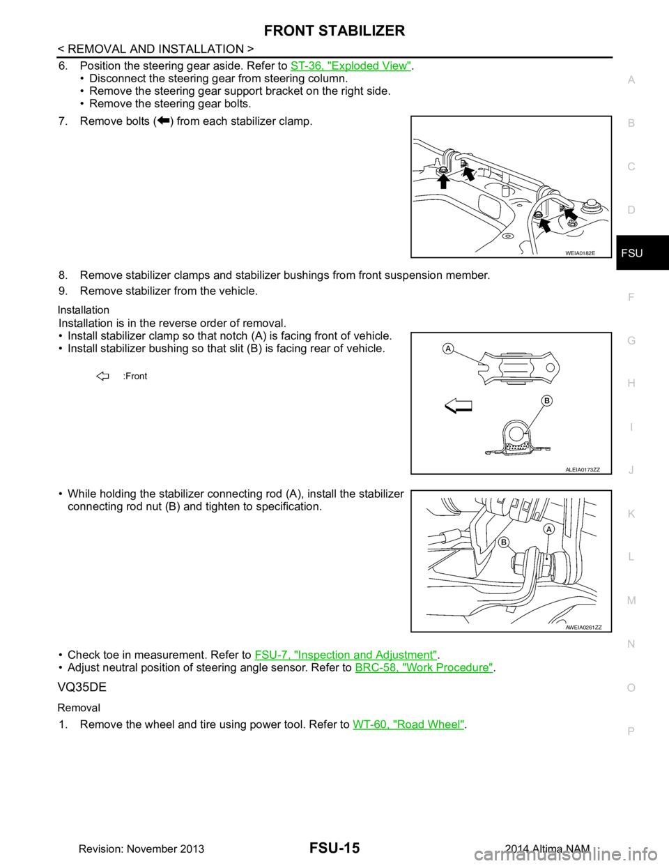
7. Remove bolts ( ) from each stabilizer clamp.
8. Remove stabilizer clamps and stabilizer bushings from front suspension member.
9. Remove stabilizer from the vehicle.
Installation
Installation is in the reverse order of removal.
• Install stabilizer clamp so that notch (A) is facing front of vehicle.
• Install stabilizer bushing so that slit (B) is facing rear of vehicle.
• While holding the stabilizer connecting rod (A), install the stabilizer connecting rod nut (B) and ti ghten to specification.
• Check toe in measurement. Refer to FSU-7, "Inspection and Adjustment"
.
• Adjust neutral position of steering angle sensor. Refer to BRC-58, "Work Procedure"
.
VQ35DE
Removal
1. Remove the wheel and tire using power tool. Refer to WT-60, "Road Wheel".
WEIA0182E
:Front
ALEIA0173ZZ
AWEIA0261ZZ
Revision: November 20132014 Altima NAM
Page 2517 of 4801
FSU-16
< REMOVAL AND INSTALLATION >
FRONT STABILIZER
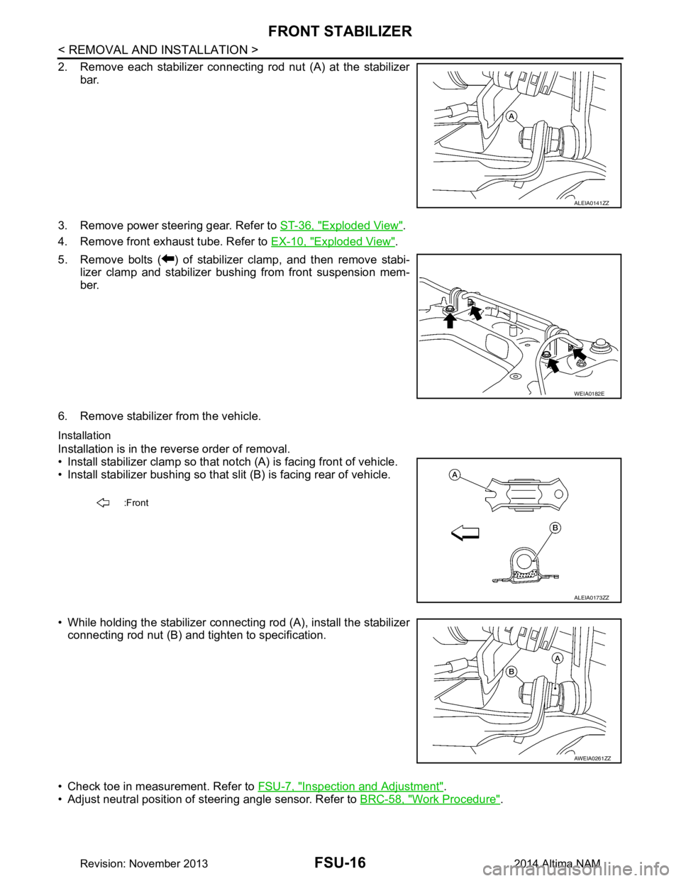
2. Remove each stabilizer connecting rod nut (A) at the stabilizerbar.
3. Remove power steering gear. Refer to ST-36, "Exploded View"
.
4. Remove front exhaust tube. Refer to EX-10, "Exploded View"
.
5. Remove bolts ( ) of stabilizer clamp, and then remove stabi- lizer clamp and stabilizer bushing from front suspension mem-
ber.
6. Remove stabilizer from the vehicle.
Installation
Installation is in the reverse order of removal.
• Install stabilizer clamp so that not ch (A) is facing front of vehicle.
• Install stabilizer bushing so that slit (B) is facing rear of vehicle.
• While holding the stabilizer connecting rod (A), install the stabilizer connecting rod nut (B) and tighten to specification.
• Check toe in measurement. Refer to FSU-7, "Inspection and Adjustment"
.
• Adjust neutral position of steering angle sensor. Refer to BRC-58, "Work Procedure"
.
ALEIA0141ZZ
WEIA0182E
:Front
ALEIA0173ZZ
AWEIA0261ZZ
Revision: November 20132014 Altima NAM
Page 2519 of 4801
FSU-18
< REMOVAL AND INSTALLATION >
STEERING KNUCKLE
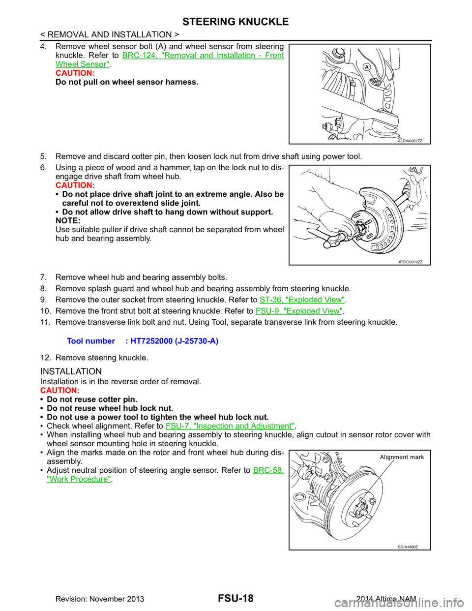
4. Remove wheel sensor bolt (A) and wheel sensor from steeringknuckle. Refer to BRC-124, "Removal and Installation - Front
Wheel Sensor".
CAUTION:
Do not pull on wheel sensor harness.
5. Remove and discard cotter pin, then loosen lock nut from drive shaft using power tool.
6. Using a piece of wood and a hammer, tap on the lock nut to dis- engage drive shaft from wheel hub.
CAUTION:
• Do not place drive shaft joint to an extreme angle. Also be
careful not to over extend slide joint.
• Do not allow drive shaft to hang down without support.
NOTE:
Use suitable puller if drive shaft cannot be separated from wheel
hub and bearing assembly.
7. Remove wheel hub and bearing assembly bolts.
8. Remove splash guard and wheel hub and bearing assembly from steering knuckle.
9. Remove the outer socket from steering knuckle. Refer to ST-36, "Exploded View"
.
10. Remove the front strut bolt at steering knuckle. Refer to FSU-9, "Exploded View"
.
11. Remove transverse link bolt and nut. Using Tool, separate transverse link from steering knuckle.
12. Remove steering knuckle.
INSTALLATION
Installation is in the reverse order of removal.
CAUTION:
• Do not reuse cotter pin.
• Do not reuse wheel hub lock nut.
• Do not use a power tool to tighten the wheel hub lock nut.
• Check wheel alignment. Refer to FSU-7, "Inspection and Adjustment"
.
• When installing wheel hub and bearing assembly to steering knuckle, align cutout in sensor rotor cover with
wheel sensor mounting hole in steering knuckle.
• Align the marks made on the rotor and front wheel hub during dis- assembly.
• Adjust neutral position of steering angle sensor. Refer to BRC-58,
"Work Procedure".
ALDIA0287ZZ
JPDIG0070ZZ
Tool number : HT7252000 (J-25730-A)
SDIA1480E
Revision: November 20132014 Altima NAM
Page 2521 of 4801
FSU-20
< UNIT REMOVAL AND INSTALLATION >
FRONT SUSPENSION ASSEMBLY
Removal and Installation
INFOID:0000000009460637
QR25DE ENGINE
Removal
1. Remove front wheel and tire using power tool. Refer to WT-55, "Adjustment".
2. Remove each brake caliper using power tool, leaving brake caliper hydraulic hose attached. Position each brake caliper aside with wire. Refer to BR-36, "BRAKE CALIPER ASSEMBLY : Exploded View"
.
CAUTION:
• Do not depress brake pedal while brake caliper is removed.
• Do not twist or stretch the brake hose.
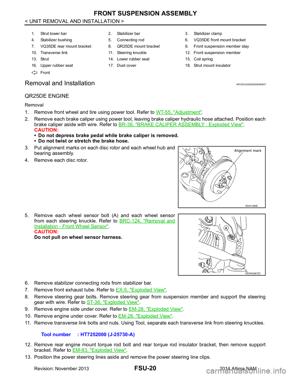
3. Put alignment marks on each disc rotor and each wheel hub and bearing assembly.
4. Remove each disc rotor.
5. Remove each wheel sensor bolt (A) and each wheel sensor from each steering knuckle. Refer to BRC-124, "Removal and
Installation - Front Wheel Sensor".
CAUTION:
Do not pull on wheel sensor harness.
6. Remove stabilizer connecting rods from stabilizer bar.
7. Remove front exhaust tube. Refer to EX-5, "Exploded View"
.
8. Remove steering gear bolts. Remove steering gear from suspension member and support the steering gear with wire. Refer to ST-36, "Exploded View"
.
9. Remove engine side under cover. Refer to EM-28, "Exploded View"
.
10. Remove engine under cover. Refer to EM-28, "Exploded View"
.
11. Remove transverse link bolts and nuts. Using Tool, separate each transverse link from steering knuckles.
12. Remove rear engine mount torque rod bolt and rear torque rod insulator bracket, then remove support bracket. Refer to EM-83, "Exploded View"
.
13. Position the power steering lines aside and remove the power steering line clips.
1. Strut tower bar 2. Stabilizer bar 3. Stabilizer clamp
4. Stabilizer bushing 5. Connecting rod 6. VQ35DE front mount bracket
7. VQ35DE rear mount bracket 8. QR25DE mount bracket 9. Front suspension member stay
10. Transverse link 11. Steering knuckle 12. Front suspension member
13. Strut 14. Lower rubber seat 15. Coil spring
16. Upper rubber seat 17. Dust cover 18. Strut mount insulator
Front
SDIA1480E
ALDIA0287ZZ
Tool number : HT7252000 (J-25730-A)
Revision: November 20132014 Altima NAM
Page 2522 of 4801
FRONT SUSPENSION ASSEMBLYFSU-21
< UNIT REMOVAL AND INSTALLATION >
C
D
F
G H
I
J
K L
M A
B
FSU
N
O P
14. Set Tool under suspension member, and remove suspension member bolts. Slowly lower Tool to remove suspension member from vehicle
15. If replacing suspension member, remove the following components from the suspension member. • transverse links.
• stabilizer bar.
• front suspension member stays.
Installation
Installation is in the reverse order of removal.
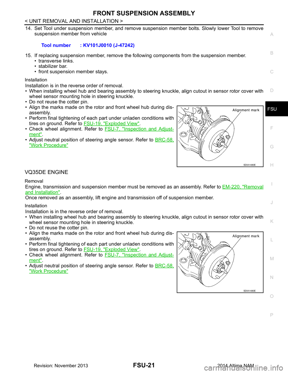
• When installing wheel hub and bearing assembly to steering knuckle, align cutout in sensor rotor cover with wheel sensor mounting hole in steering knuckle.
• Do not reuse the cotter pin.
• Align the marks made on the rotor and front wheel hub during dis- assembly.
• Perform final tightening of each part under unladen conditions with tires on ground. Refer to FSU-19, "Exploded View"
.
• Check wheel alignment. Refer to FSU-7, "Inspection and Adjust-
ment".
• Adjust neutral position of steering angle sensor. Refer to BRC-58,
"Work Procedure"
VQ35DE ENGINE
Removal
Engine, transmission and suspension member must be removed as an assembly. Refer to EM-220, "Removal
and Installation".
Once removed as an assembly, lift engine and transmission off of suspension member.
Installation
Installation is in the reverse order of removal.
• When installing wheel hub and bearing assembly to steering knuckle, align cutout in sensor rotor cover with
wheel sensor mounting hole in steering knuckle.
• Do not reuse the cotter pin.
• Align the marks made on the rotor and front wheel hub during dis-
assembly.
• Perform final tightening of each part under unladen conditions with tires on ground. Refer to FSU-19, "Exploded View"
.
• Check wheel alignment. Refer to FSU-7, "Inspection and Adjust-
ment".
• Adjust neutral position of steering angle sensor. Refer to BRC-58,
"Work Procedure"
Tool number : KV101J0010 (J-47242)
SDIA1480E
SDIA1480E
Revision: November 20132014 Altima NAM
Page 2541 of 4801

ABBREVIATIONSGI-13
< HOW TO USE THIS MANUAL >
C
D E
F
G H
I
J
K L
M B
GI
N
O PABBREVIATIONS
Abbreviation ListINFOID:0000000009462979
The following ABBREVIATIONS are used:
A
B
C
D
ABBREVIATION DESCRIPTION A/C Air conditioner
A/C Air conditioning
A/F sensor Air fuel ratio sensor A/T Automatic transaxle/transmission
ABS Anti-lock braking system
ACCS Advance climate control system ACL Air cleaner
AP Accelerator pedal
APP Accelerator pedal position AV Audio visual
AVM Around view monitor
AWD All wheel drive
ABBREVIATION DESCRIPTION BARO Barometric pressureBCI Backup collision intervention
BCM Body control module
BLSD Brake limited slip differential BPP Brake pedal positionBSI Blind spot intervention
BSW Blind spot warning
ABBREVIATION DESCRIPTION CKP Crankshaft positionCL Closed loop
CMP Camshaft position CPP Clutch pedal positionCTP Closed throttle position
CVT Continuously variable transaxle/transmission
ABBREVIATION DESCRIPTION D
1Drive range first gear
D
2Drive range second gear
D
3Drive range third gear
D
4Drive range fourth gear
DCA Distance control assist
DDS Downhill drive support DFI Direct fuel injection system
DLC Data link connector
DTC Diagnostic trouble code
Revision: November 20132014 Altima NAMRevision: November 20132014 Altima NAM