2014 NISSAN TEANA sensor
[x] Cancel search: sensorPage 2274 of 4801

EXL-8
< SYSTEM DESCRIPTION >
COMPONENT PARTS
Component Description
INFOID:0000000009463542
1. BCM (view with combination meter re-
moved) 2. Combination switch
(lighting and turn signal switch) 3. IPDM E/R, (Headlamp high relay,
Headlamp low relay, Tail lamp relay
and Front fog lamp relay (if equipped))
4. Fuse, fusible link and relay box (Stop lamp relay) 5. Combination meter 6. Parking brake switch
7. Stop lamp switch 8. Hazard switch 9. Optical sensor
10. Front door switch LH (RH similar) 11. Rear door switch LH
(RH similar) 12. Daytime light relay
(if equipped)
Part Description
BCM Controls the exterior lighting system.
Combination switch
(Lighting & turn signal switch) Refer to
BCS-8, "COMBINATION SWITCH READIN G SYSTEM : System Description"
.
IPDM E/R Controls the integrated relays and supplies voltage to the load according to the request from the BCM
via CAN communication.
Stop lamp switch Transmits power to the stop lamp relay when the brake pedal is pressed to operate stop lamps.
Combination meter Refer to MWI-9, "METER SYSTEM : System Description"
.
Daytime light relay
(if equipped) Sends power to the daytime lamp when operated by the IPDM E/R.
Stop lamp relay Transmits power to the stop lamps when the brake pedal is pressed.
Front door switch LH/RH Transmits the door open signal to the BCM.
Rear door switch LH/RH
Optical sensor Optical sensor converts the outside brightness (lux) to voltage and transmits the optical sensor signal
to BCM to operate the auto light system.
Parking brake switch Transmits the parking brake switch signal to the combination meter to operate the auto light system.
Hazard switch Inputs the hazard switch signal to BCM.
Revision: November 20132014 Altima NAMRevision: November 20132014 Altima NAM
Page 2276 of 4801

EXL-10
< SYSTEM DESCRIPTION >
SYSTEM
HIGH BEAM OPERATION/FLASH-TO-PASS OPERATION
With the lighting switch in the 2nd position and placed in HIGH position, the BCM receives input requesting the
headlamp high beams to illuminate. The flash to pass f eature can be used any time and also sends a signal to
the BCM. This input is communicated to the IPDM E/R across the CAN communication lines. The CPU of the
combination meter controls the ON/OFF status off the HIGH BEAM indicator. The CPU of the IPDM E/R con-
trols the headlamp high relay coil which supplies power to the high beam headlamps.
The combination meter receives a high beam request signal (ON) through the CAN communication lines and
turns the high beam indicator lamp ON.
EXTERIOR LAMP BATTERY SAVER CONTROL
With the combination switch (lighting and turn signal switch) in the 2nd position and the ignition switch is
turned from ON or ACC to OFF, the battery saver feature is activated.
Under this condition, the headlamps remain illuminated fo r a period of time, unless the lighting switch position
is changed. If the lighting switch position is changed, then the headlamps are turned off.
AUTO LIGHT SYSTEM
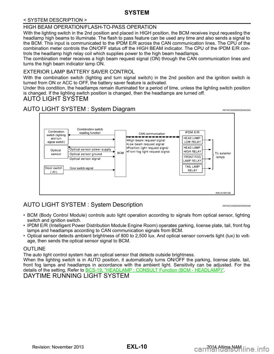
AUTO LIGHT SYSTEM : System DiagramINFOID:0000000009463545
AUTO LIGHT SYSTEM : System DescriptionINFOID:0000000009463546
• BCM (Body Control Module) controls auto light operati on according to signals from optical sensor, lighting
switch and ignition switch.
• IPDM E/R (Intelligent Power Distribution Module Engine R oom) operates parking, license plate, tail, front fog
lamps and headlamps according to CAN communication signals from BCM.
• Optical sensor detects ambient brightness of 800 to 2,500 lux. And optical sensor converts light (lux) to volt-
age, then sends the optical sensor signal to BCM.
OUTLINE
The auto light control system has an optical sensor that detects outside brightness.
When the lighting switch is in AUTO position, it autom atically turns ON/OFF the parking, license plate, tail,
front fog lamps and headlamps in accordance with the am bient light. Sensitivity can be adjusted. For the
details of the setting, Refer to BCS-19, "HEADLAMP : CONSULT Function (BCM - HEADLAMP)"
.
DAYTIME RUNNING LIGHT SYSTEM
AWLIA1981GB
Revision: November 20132014 Altima NAMRevision: November 20132014 Altima NAM
Page 2284 of 4801

EXL-18
< SYSTEM DESCRIPTION >
DIAGNOSIS SYSTEM (BCM)
HEADLAMP
HEADLAMP : CONSULT Function (BCM - HEADLAMP)INFOID:0000000009956425
CAUTION:
After disconnecting the CONSULT vehicle interface (VI) from the data link connector, the ignition must
be cycled OFF → ON (for at least 5 seconds) → OFF. If this step is not performed, the BCM may not go
to ”sleep mode”, potentially causing a di scharged battery and a no-start condition.
DATA MONITOR
ACTIVE TEST
RAP system RETAINED PWR ×
Signal buffer system SIGNAL BUFFER ×
TPMS AIR PRESSURE MONITOR ××××
System Sub System
Direct Diagnostic Mode
Ecu Identification
Self Diagnostic Result
Data Monitor
Active Test
Work support
Configuration
CAN Diag Support Mntr
Monitor Item [Unit] Description
PUSH SW [On/Off] Indicates condition of push-button ignition switch.
ENGINE STATE [STOP/STALL/CRANK/RUN] Indicates engine st atus received from ECM on CAN communication line.
VEH SPEED 1 [km/h] Indicates vehicle speed signal received from ABS on CAN communication line.
TURN SIGNAL R [On/Off]
Indicates condition of combination switch.
TURN SIGNAL L [On/Off]
TAIL LAMP SW [On/Off]
HI BEAM SW [On/Off]
HEAD LAMP SW 1 [On/Off]
HEAD LAMP SW 2 [On/Off]
PASSING SW [On/Off]
AUTO LIGHT SW [On/Off]
FR FOG SW [On/Off]
DOOR SW-DR [On/Off] Indicates condition of front door switch LH.
DOOR SW-AS [On/Off] Indicates condition of front door switch RH.
DOOR SW-RR [On/Off] Indicates condition of rear door switch RH.
DOOR SW-RL [On/Off] Indicates condition of rear door switch LH.
DOOR SW-BK [On/Off] Indicates condition of trunk switch.
OPTI SEN (DTCT) [V] Indicates outside brightness voltage signal from optical sensor.
OPTI SEN (FILT) [V] Indicates outside brightness voltage signal from optical sensor filtered by BCM.
Test Item Description
FR FOG LAMP This test is able to check front fog lamp operation [On/Off].
DAYTIME RUNNING LIGHT This test is able to check daytime running la mp operation [On/Off].
ILL DIM SIGNAL This test is able to check head lamp illumination dimming operation [On/Off].
Revision: November 20132014 Altima NAMRevision: November 20132014 Altima NAM
Page 2286 of 4801

EXL-20
< SYSTEM DESCRIPTION >
DIAGNOSIS SYSTEM (BCM)
COMB SW
COMB SW : CONSULT Function (BCM - COMB SW)INFOID:0000000009956484
CAUTION:
After disconnecting the CONSULT vehicle interface (VI) from the data link connector, the ignition must
be cycled OFF → ON (for at least 5 seconds) → OFF. If this step is not performed, the BCM may not go
to ”sleep mode”, potentially causing a di scharged battery and a no-start condition.
DATA MONITOR
BATTERY SAVER
BATTERY SAVER : CONSULT Function (BCM - BATTERY SAVER)INFOID:0000000009956486
CAUTION:
After disconnecting the CONSULT vehicle interface (VI) from the data link connector, the ignition must
be cycled OFF → ON (for at least 5 seconds) → OFF. If this step is not performed, the BCM may not go
to ”sleep mode”, potentially causing a di scharged battery and a no-start condition.
DATA MONITOR
Monitor Item [Unit] Description
FR WIPER HI [On/Off]
Indicates condition of wiper operation of combination switch.
FR WIPER LOW [On/Off]
FR WASHER SW [On/Off]
FR WIPER INT [On/Off]
INT VOLUME [1 - 7] Indicates condition of intermittent wiper operation of combination switch.
TURN SIGNAL R [On/Off] Indicates condition of right turn signal operation of combination switch.
TURN SIGNAL L [On/Off] Indicates condition of left turn signal operation of combination switch.
TAIL LAMP SW [On/Off] Indicates condition of tail lamp switch operation of combination switch.
HI BEAM SW [On/Off] Indicates condition of Hi beam switch operation of combination switch.
HEAD LAMP SW 1 [On/Off] Indicates condition of head lamp switch 1 operation of combination switch.
HEAD LAMP SW 2 [On/Off] Indicates condition of head lamp switch 2 operation of combination switch.
PASSING SW [On/Off] Indicates condition of pass ing switch operation of combination switch.
AUTO LIGHT SW [On/Off] Indicates condition of auto light switch operation of combination switch.
FR FOG SW [On/Off] Indicates condition of front fog lamp switch operation of combination switch.
Monitor Item [Unit] Description
REQ SW -DR [On/Off] Indicates condition of door request switch LH.
REQ SW -AS [On/Off] Indicates condition of door request switch RH.
PUSH SW [On/Off] Indicates condition push-button ignition switch.
UNLK SEN -DR [On/Off] Indicates condition of door unlock sensor.
DOOR SW-DR [On/Off] Indicates condition of front door switch LH.
DOOR SW-AS [On/Off] Indicates condition of front door switch RH.
DOOR SW-RR [On/Off] Indicates condition of rear door switch RH.
DOOR SW-RL [On/Off] Indicates condition of rear door switch LH.
DOOR SW-BK [On/Off] Indicates condition of trunk switch.
CDL LOCK SW [On/Off] Indicates condition of lock signal from door lock and unlock switch.
CDL UNLOCK SW [On/Off] Indicates condition of unlock signal from door lock and unlock switch.
KEY CYL LK-SW [On/Off] Indicates condition of lo ck signal from door key cylinder switch.
Revision: November 20132014 Altima NAMRevision: November 20132014 Altima NAM
Page 2376 of 4801

EXL-110
< DTC/CIRCUIT DIAGNOSIS >
OPTICAL SENSOR
OPTICAL SENSOR
DescriptionINFOID:0000000009463600
The optical sensor measures ambient light and transmits the optical sensor signal to the BCM.
Component Function CheckINFOID:0000000009463601
1.CHECK OPTICAL SENSOR SIGNAL BY CONSULT
CONSULT
1. Turn the ignition switch ON.
2. Select OPTI SEN of BCM (HEAD LAMP) DATA MONITOR item.
3. Turn the lighting switch to AUTO.
*: Illuminates the optical sensor. The value may be less than the standard value if brightness is weak.
Is the inspection result normal?
YES >> Optical sensor is normal.
NO >> Refer to EXL-110, "Diagnosis Procedure"
.
Diagnosis ProcedureINFOID:0000000009463602
Regarding Wiring Diagram information, refer to EXL-47, "Wiring Diagram".
1.CHECK OPTICAL SENSOR POWER SUPPLY INPUT
1. Turn the ignition switch OFF.
2. Disconnect the optical sensor harness connector M66.
3. Turn the ignition switch ON.
4. Turn the lighting switch to AUTO.
5. Check the voltage between the optical sensor harness connector M66 and ground.
Is the inspection result normal?
YES >> GO TO 2.
NO >> GO TO 3.
2.CHECK OPTICAL SENSOR GROUND CIRCUIT
1. Turn the ignition switch OFF.
2. Check continuity between the optical sensor harness connector M15 and ground.
Is the inspection result normal?
YES >> GO TO 4.
NO >> GO TO 5.
3.CHECK OPTICAL SENSOR POWER SUPPLY FOR OPEN CIRCUIT
1. Turn the ignition switch OFF.
2. Disconnect the BCM harness connector M17.
Monitor item Condition Voltage
OPTI SEN (DTCT) When outside of vehicle is bright 3.1V or more *
When outside of vehicle is dark 0.6V or less
(+) (− ) Vo l ta g e
(Approx.)
Connector Terminal
M66 1 Ground 5 V
(+) (− )Continuity
Connector Terminal
M66 3 Ground Yes
Revision: November 20132014 Altima NAMRevision: November 20132014 Altima NAM
Page 2377 of 4801

OPTICAL SENSOREXL-111
< DTC/CIRCUIT DIAGNOSIS >
C
D E
F
G H
I
J
K
M A
B
EXL
N
O P
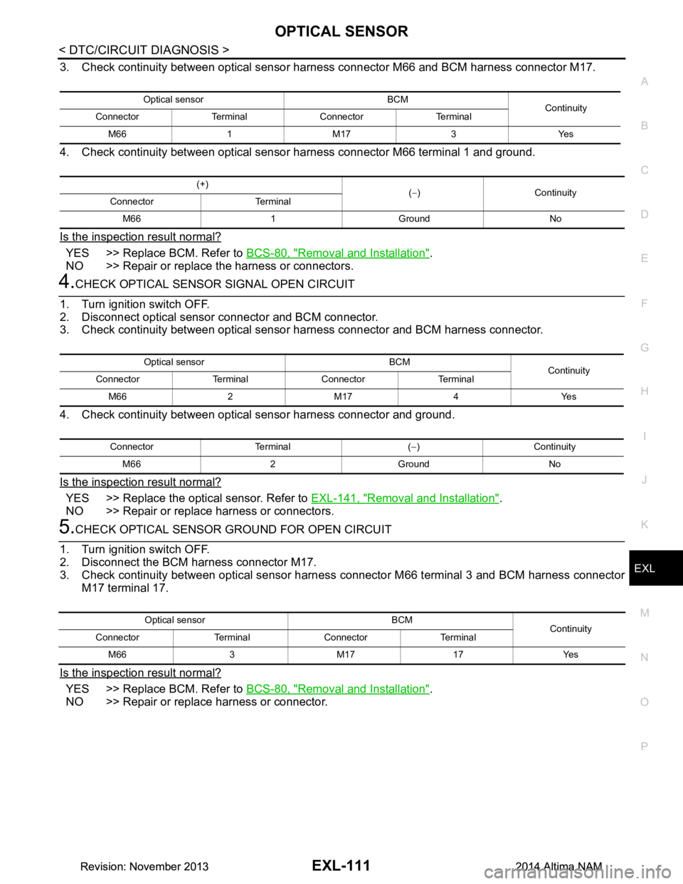
3. Check continuity between optical sensor harness connector M66 and BCM harness connector M17.
4. Check continuity between optical sensor harness connector M66 terminal 1 and ground.
Is the inspection result normal?
YES >> Replace BCM. Refer to BCS-80, "Removal and Installation".
NO >> Repair or replace the harness or connectors.
4.CHECK OPTICAL SENSOR SIGNAL OPEN CIRCUIT
1. Turn ignition switch OFF.
2. Disconnect optical sensor connector and BCM connector.
3. Check continuity between optical sensor harness connector and BCM harness connector.
4. Check continuity between optical sensor harness connector and ground.
Is the inspection result normal?
YES >> Replace the optical sensor. Refer to EXL-141, "Removal and Installation".
NO >> Repair or replace harness or connectors.
5.CHECK OPTICAL SENSOR GROUND FOR OPEN CIRCUIT
1. Turn ignition switch OFF.
2. Disconnect the BCM harness connector M17.
3. Check continuity between optical sensor harnes s connector M66 terminal 3 and BCM harness connector
M17 terminal 17.
Is the inspection result normal?
YES >> Replace BCM. Refer to BCS-80, "Removal and Installation".
NO >> Repair or replace harness or connector.
Optical sensor BCM Continuity
Connector Terminal Connector Terminal
M66 1 M17 3 Yes
(+) (− )Continuity
Connector Terminal
M66 1 Ground No
Optical sensor BCM Continuity
Connector Terminal Connector Terminal
M66 2 M17 4 Yes
Connector Terminal ( −)Continuity
M66 2 Ground No
Optical sensor BCM Continuity
Connector Terminal Connector Terminal
M66 3 M17 17 Yes
Revision: November 20132014 Altima NAMRevision: November 20132014 Altima NAM
Page 2381 of 4801

EXTERIOR LIGHTING SYSTEM SYMPTOMSEXL-115
< SYMPTOM DIAGNOSIS >
C
D E
F
G H
I
J
K
M A
B
EXL
N
O P
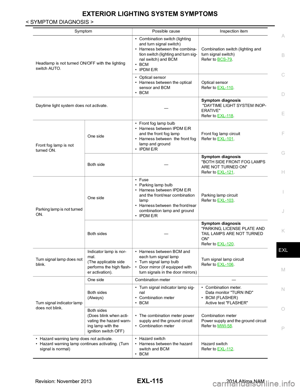
Headlamp is not turned ON/OFF with the lighting
switch AUTO. • Combination switch (lighting
and turn signal switch)
• Harness between the combina- tion switch (lighting and turn sig-
nal switch) and BCM
•BCM
• IPDM E/R Combination switch (lighting and
turn signal switch)
Refer to BCS-79.
• Optical sensor
• Harness between the optical
sensor and BCM
•BCM Optical sensor
Refer to EXL-110
.
Daytime light system does not activate. —Symptom diagnosis
"DAYTIME LIGHT SYSTEM INOP-
ERATIVE"
Refer to EXL-118
.
Front fog lamp is not
turned ON. One side
• Front fog lamp bulb
• Harness between IPDM E/R
and the front fog lamp
• Harness between the front fog lamp and ground
• IPDM E/R Front fog lamp circuit
Refer to EXL-101
.
Both side — Symptom diagnosis
"BOTH SIDE FRONT FOG LAMPS
ARE NOT TURNED ON"
Refer to EXL-121
.
Parking lamp is not turned
ON. One side•Fuse
• Parking lamp bulb
• Harness between IPDM E/R
and the front/rear combination
lamp
• Harness between the front/rear
combination lamp and ground
• IPDM E/R Parking lamp circuit
Refer to EXL-103
.
Both sides — Symptom diagnosis
"PARKING, LICENSE PLATE AND
TAIL LAMPS ARE NOT TURNED
ON"
Refer to EXL-120
.
Turn signal lamp does not
blink. Indicator lamp is nor-
mal.
(The applicable side
performs the high flash-
er activation). • Harness between BCM and
each turn signal lamp
• Turn signal lamp bulb
• Door mirror (if equipped with
turn signals in the door mirrors) Turn signal lamp circuit
Refer to EXL-106
.
Turn signal indicator lamp
does not blink. One side Combination meter —
Both sides
(Always) • Turn signal indicator lamp sig-
nal
• Combination meter
•BCM • Combination meter.
Data monitor "TURN IND"
• BCM (FLASHER) Active test "FLASHER"
Both sides
(Does blink when acti-
vating the hazard warn-
ing lamp with the
ignition switch OFF) • The combination meter power
supply and the ground circuit
• Combination meter Combination meter
Power supply and the ground circuit
Refer to MWI-58
.
• Hazard warning lamp does not activate.
• Hazard warning lamp continues activating. (Turn signal is normal) • Hazard switch
• Harness between the hazard switch and BCM
•BCM Hazard switch
Refer to EXL-112
.
Symptom Possible cause Inspection item
Revision: November 20132014 Altima NAMRevision: November 20132014 Altima NAM
Page 2407 of 4801

OPTICAL SENSOREXL-141
< REMOVAL AND INSTALLATION >
C
D E
F
G H
I
J
K
M A
B
EXL
N
O P
OPTICAL SENSOR
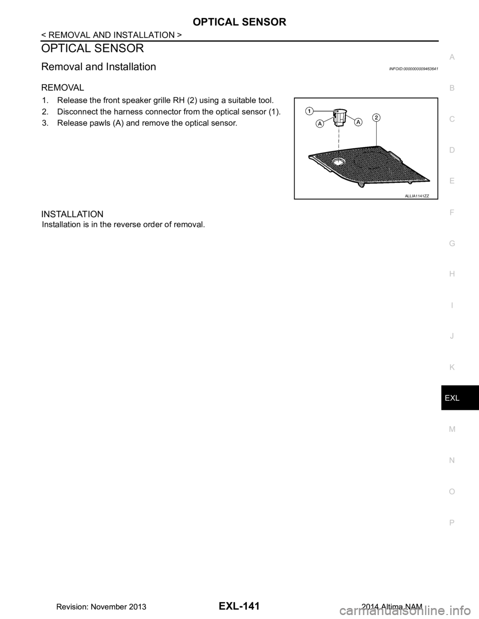
Removal and InstallationINFOID:0000000009463641
REMOVAL
1. Release the front speaker grille RH (2) using a suitable tool.
2. Disconnect the harness connector from the optical sensor (1).
3. Release pawls (A) and remove the optical sensor.
INSTALLATION
Installation is in the reverse order of removal.
ALLIA1141ZZ
Revision: November 20132014 Altima NAMRevision: November 20132014 Altima NAM