2014 NISSAN TEANA Center
[x] Cancel search: CenterPage 2388 of 4801
EXL-122
< PERIODIC MAINTENANCE >
HEADLAMP
PERIODIC MAINTENANCE
HEADLAMP
Aiming AdjustmentINFOID:0000000009463617
PREPARATION BEFORE ADJUSTING
Before performing aiming adjustment, check the following:
• Ensure all tires are inflated to correct pressure.
• Place vehicle and screen on level surface.
• Ensure there is no load in vehicle other than the driver (or equivalent weight placed in driver's position).
• Coolant and engine oil filled to correct level, and fuel tank full.
• Remove cargo and/or luggage to maintain an unloaded vehicle condition.
• Confirm spare tire, jack and tools are properly stowed.
• Carefully wipe off any dirt from headlamp lens. CAUTION:
Do not use organic solvent (thinner, gasoline etc.)
• Place a driver or equivalent weight of 68.5 kg (150 lb) on the driver seat.
• By hand, bounce the front and rear of the vehicle to settle the suspension and eliminate any static load.
• Place the front tires in the straight ahead position.
• Aim each headlamp individually and ensure other headlamp beam pattern is blocked from screen.
NOTE:
• For headlamp aiming details, refer to regulations in your area.
• By regulation, no means for horizontal aim adjustment is provided from the factory; only vertical aim is
adjustable.
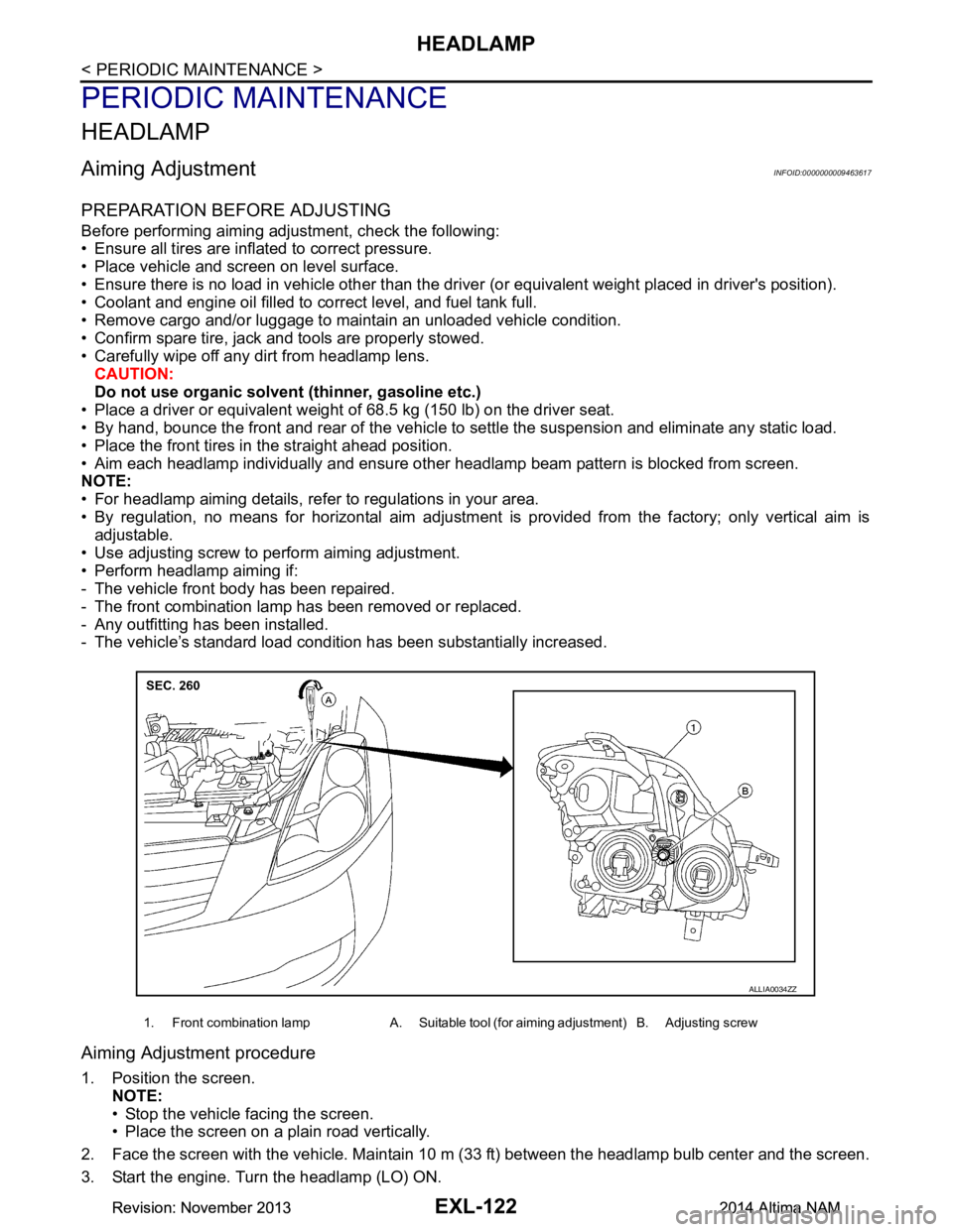
• Use adjusting screw to perform aiming adjustment.
• Perform headlamp aiming if:
- The vehicle front body has been repaired.
- The front combination lamp has been removed or replaced.
- Any outfitting has been installed.
- The vehicle’s standard load condition has been substantially increased.
Aiming Adjustment procedure
1. Position the screen.
NOTE:
• Stop the vehicle facing the screen.
• Place the screen on a plain road vertically.
2. Face the screen with the vehicle. Maintain 10 m (33 ft) between the headlamp bulb center and the screen.
3. Start the engine. Turn the headlamp (LO) ON.
1. Front combination lamp A. Suitable tool (for aiming adjustment) B. Adjusting screw
ALLIA0034ZZ
Revision: November 20132014 Altima NAMRevision: November 20132014 Altima NAM
Page 2389 of 4801
HEADLAMPEXL-123
< PERIODIC MAINTENANCE >
C
D E
F
G H
I
J
K
M A
B
EXL
N
O P
CAUTION:
Do not cover the lens surface with tape, etc. The lens is made of resin.
NOTE:
• Aim each headlamp individually and ensure other headlamp beam pattern is blocked from screen.
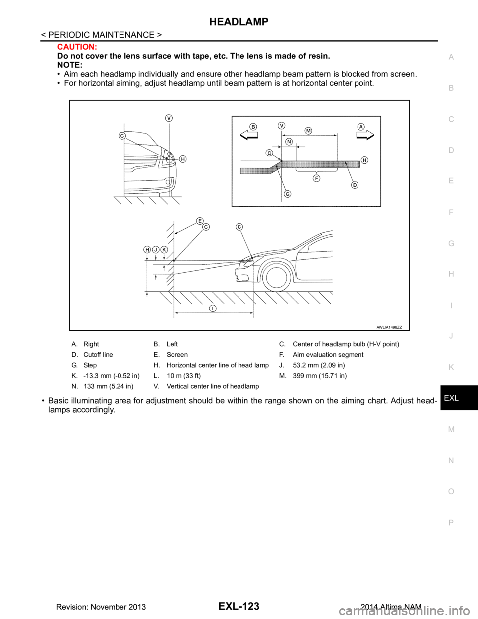
• For horizontal aiming, adjust headlamp until beam pattern is at horizontal center point.
• Basic illuminating area for adjustment should be with in the range shown on the aiming chart. Adjust head-
lamps accordingly.
A. Right B. Left C. Center of headlamp bulb (H-V point)
D. Cutoff line E. Screen F. Aim evaluation segment
G. Step H. Horizontal center line of head lamp J. 53.2 mm (2.09 in)
K. -13.3 mm (-0.52 in) L. 10 m (33 ft) M. 399 mm (15.71 in)
N. 133 mm (5.24 in) V. Vertical center line of headlamp
AWLIA1498ZZ
Revision: November 20132014 Altima NAMRevision: November 20132014 Altima NAM
Page 2390 of 4801
EXL-124
< PERIODIC MAINTENANCE >
FRONT FOG LAMP
FRONT FOG LAMP
Aiming AdjustmentINFOID:0000000009463618
PREPARATION BEFORE ADJUSTING
The fog lamp is a semi-sealed beam type which uses a replaceable halogen bulb. Before performing aiming
adjustment procedure, check the following:
• Ensure all tires are inflated to correct pressure.
• Place vehicle and screen on level surface.
• Ensure there is no load in vehicle other than the driver (or equivalent weight placed in driver's position).
• Coolant and engine oil filled to correct level, and fuel tank full.
• Remove cargo and/or luggage to maintain an unloaded vehicle condition.
• Confirm spare tire, jack and tools are properly stowed.
• Carefully wipe off any dirt from headlamp lens. CAUTION:
Do not use organic solvent (thinner, gasoline etc.)
• Place a driver or equivalent weight of 68.5 kg (150 lb) on the driver seat.
• By hand, bounce the front and rear of the vehicle to settle the suspension and eliminate any static load.
• Place the front tires in the straight ahead position.
• Aim each headlamp individually and ensure other headlamp beam pattern is blocked from screen.
NOTE:
• For headlamp aiming details, refer to regulations in your area.
• By regulation, no means for horizontal aim adjustment is provided from the factory; only vertical aim is
adjustable.
• Use adjusting screw to perform aiming adjustment.
• Perform headlamp aiming if:
- The vehicle front body has been repaired.
- The front combination lamp has been removed or replaced.
- Any outfitting has been installed.
- The vehicle’s standard load condition has been substantially increased.
Aiming Adjustment Procedure
1. Place the screen. NOTE:
• Stop the vehicle facing the wall.
• Place the board on a plain road vertically.
2. Face the vehicle with the screen. Maintain 7.62 m (25.0 ft) between the front fog lamp center and the
screen.
3. Start the engine. Turn the front fog lamp ON. NOTE:
Shut off the headlamp light with the board to prevent from illuminating the adjustment screen.
CAUTION:
Do not cover the lens surface with a tape etc. The lens is made of resin.
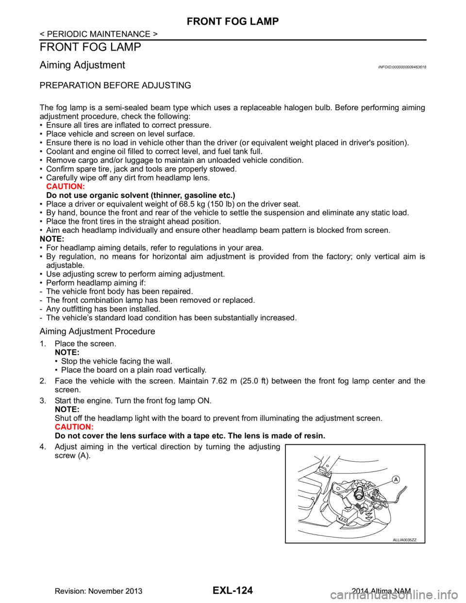
4. Adjust aiming in the vertical direction by turning the adjusting screw (A).
ALLIA0035ZZ
Revision: November 20132014 Altima NAMRevision: November 20132014 Altima NAM
Page 2391 of 4801
FRONT FOG LAMPEXL-125
< PERIODIC MAINTENANCE >
C
D E
F
G H
I
J
K
M A
B
EXL
N
O P
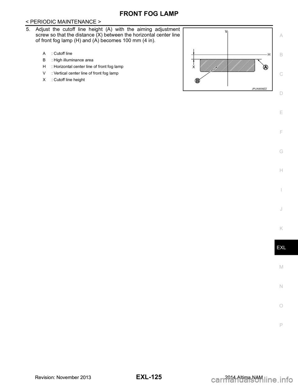
5. Adjust the cutoff line height (A) with the aiming adjustment screw so that the distance (X) between the horizontal center line
of front fog lamp (H) and (A) becomes 100 mm (4 in).
A : Cutoff line
B : High illuminance area
H : Horizontal center line of front fog lamp
V : Vertical center line of front fog lamp
X : Cutoff line height
JPLIA0008ZZ
Revision: November 20132014 Altima NAMRevision: November 20132014 Altima NAM
Page 2426 of 4801

EXT-12
< PERIODIC MAINTENANCE >
SQUEAK AND RATTLE TROUBLE DIAGNOSES
INSTRUMENT PANEL
Most incidents are caused by contact and movement between:
1. Cluster lid A and the instrument panel
2. Acrylic lens and combination meter housing
3. Instrument panel to front pillar finisher
4. Instrument panel to windshield
5. Instrument panel pins
6. Wiring harnesses behind the combination meter
7. A/C defroster duct and duct joint
These incidents can usually be located by tapping or moving the components to duplicate the noise or by
pressing on the components while driving to stop the noise. Most of these incidents can be repaired by apply-
ing felt cloth tape or silicone spray (in hard to reach areas). Urethane pads can be used to insulate wiring har-
ness.
CAUTION:
Do not use silicone spray to isolate a squeak or ra ttle. If you saturate the area with silicone, you will
not be able to recheck the repair.
CENTER CONSOLE
Components to pay attention to include:
1. Shift selector assembly cover to finisher
2. A/C control unit and cluster lid C
3. Wiring harnesses behind audio and A/C control unit
The instrument panel repair and isolation pr ocedures also apply to the center console.
DOORS
Pay attention to the:
1. Finisher and inner panel making a slapping noise
2. Inside handle escutcheon to door finisher
3. Wiring harnesses tapping
4. Door striker out of alignment causing a popping noise on starts and stops
Tapping or moving the components or pressing on them wh ile driving to duplicate the conditions can isolate
many of these incidents. You can usually insulate the areas with felt cloth tape or insulator foam blocks from
the NISSAN Squeak and Rattle Kit (J-50397) to repair the noise.
TRUNK
Trunk noises are often caused by a loose jack or loose items put into the trunk by the owner.
In addition look for:
1. Trunk lid bumpers out of adjustment
2. Trunk lid striker out of adjustment
3. The trunk lid torsion bars knocking together
4. A loose license plate or bracket
Most of these incidents can be repaired by adjusting, se curing or insulating the item(s) or component(s) caus-
ing the noise.
SUNROOF/HEADLINING
Noises in the sunroof/headlining area c an often be traced to one of the following:
1. Sunroof lid, rail, linkage or seals making a rattle or light knocking noise
2. Sun visor shaft shaking in the holder
3. Front or rear windshield touching headlining and squeaking
Again, pressing on the components to stop the noise while duplicating the conditions can isolate most of these
incidents. Repairs usually consist of insulating with felt cloth tape.
OVERHEAD CONSOLE (FRONT AND REAR)
Overhead console noises are often caused by the c onsole panel clips not being engaged correctly. Most of
these incidents are repaired by pushing up on the c onsole at the clip locations until the clips engage.
In addition look for:
Revision: November 20132014 Altima NAM
Page 2431 of 4801
FRONT BUMPEREXT-17
< REMOVAL AND INSTALLATION >
C
D E
F
G H
I
J
L
M A
B
EXT
N
O P
Removal and InstallationINFOID:0000000009460995
REMOVAL
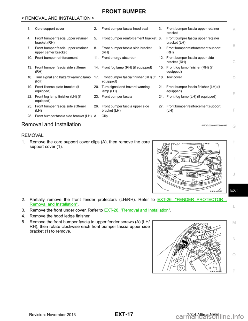
1. Remove the core support cover clips (A), then remove the core support cover (1).
2. Partially remove the front fender protectors (LH/RH). Refer to EXT-26, "FENDER PROTECTOR :
Removal and Installation".
3. Remove the front under cover. Refer to EXT-28, "Removal and Installation"
.
4. Remove the hood ledge finisher.
5. Remove the front bumper fascia to upper fender screws (A) (LH/ RH), then rotate clockwise each front bumper fascia upper side
bracket (1) to remove.
1. Core support cover 2. Front bumper fascia hood seal 3. Front bumper fascia upper retainer
bracket
4. Front bumper fascia upper retainer bracket (RH) 5. Front bumper reinforcement bracket 6. Front bumper fascia upper retainer
bracket (LH)
7. Front bumper fascia upper retainer upper center bracket 8. Front bumper fascia side bracket
(RH) 9. Front bumper reinforcement support
(RH)
10. Front bumper reinforcement 11. Front energy absorber 12. Front bumper fascia upper side bracket (RH)
13. Front bumper fascia side stiffener (RH) 14. Front fog lamp (RH) (if equipped) 15. Front fog lamp finisher (RH) (if
equipped)
16. Turn signal and hazard warning lamp (RH) 17. Front bumper fascia finisher (RH) (if
equipped) 18. Tow cover
19. Front license plate bracket (if equipped) 20. Turn signal and hazard warning
lamp (LH) 21. Front bumper fascia finisher (LH) (if
equipped)
22. Front fog lamp finisher (LH) (if equipped) 23. Front bumper fascia 24. Front fog lamp (LH) (if equipped)
25. Front bumper fascia side stiffener (LH) 26. Front bumper fascia upper side
bracket (LH) 27. Front bumper reinforcement support
(LH)
28. Front bumper fascia side bracket (LH) A. Clip
ALKIA2602ZZ
ALKIA2603ZZ
Revision: November 20132014 Altima NAM
Page 2444 of 4801
EXT-30
< REMOVAL AND INSTALLATION >
MUDGUARD
MUDGUARD
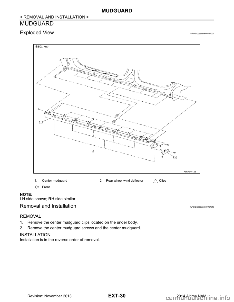
Exploded ViewINFOID:0000000009461009
NOTE:
LH side shown; RH side similar.
Removal and InstallationINFOID:0000000009461010
REMOVAL
1. Remove the center mudguard clips located on the under body.
2. Remove the center mudguard screws and the center mudguard.
INSTALLATION
Installation is in the reverse order of removal.
1. Center mudguard 2. Rear wheel wind deflector Clips
Front
ALKIA2661ZZ
Revision: November 20132014 Altima NAM
Page 2492 of 4801
FL-12
< REMOVAL AND INSTALLATION >
FUEL TANK
8. Remove rear wheel and tire using power tool. Refer to WT-55, "Adjustment".
9. Remove rear brake pads. Refer to BR-38, "BRAKE PAD : Removal and Installation"
.
10. Remove rear torque members and rear disc brake rotor.
11. Disconnect rear parking brake shoe, and remove rear cables from toggle lever. Refer to PB-9, "Removal
and Installation".
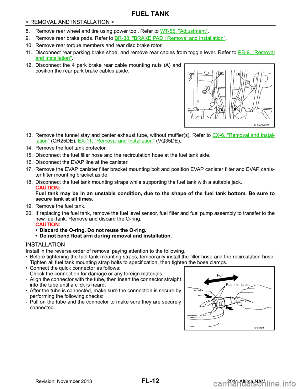
12. Disconnect the 4 park brake rear cable mounting nuts (A) and position the rear park brake cables aside.
13. Remove the tunnel stay and center exhaust tube, without muffler(s). Refer to EX-6, "Removal and Instal-
lation" (QR25DE), EX-11, "Removal and Installation" (VQ35DE).
14. Remove the fuel tank protector.
15. Disconnect the fuel filler hose and the recirculation hose at the fuel tank side.
16. Disconnect the EVAP line at the canister.
17. Remove the EVAP canister filter bracket mounti ng bolt and position EVAP canister filter and EVAP canis-
ter filter mounting bracket aside.
18. Disconnect the fuel tank mounting straps while supporting the fuel tank with a suitable jack. CAUTION:
Fuel tank may be in an unstable condition, due to the shape of the fuel tank bottom. Be sure to
secure tank at all times.
19. Remove the fuel tank.
20. If replacing the fuel tank, remove the fuel level sens or, fuel filter and fuel pump assembly to transfer to the
new fuel tank. Remove and discard the O-ring.
CAUTION:
• Discard the O-ring. Do not reuse the O-ring.
• Do not bend float arm during removal and installation.
INSTALLATION
Install in the reverse order of removal paying attention to the following.
• Before tightening the fuel tank mounting straps, tempor arily install the filler hose and the recirculation hose.
Tighten all fuel tank mounting strap bolts to specification, then tighten the hose clamps.
• Connect the quick connector as follows:
- Check the connection for damage or any foreign materials.
- Align the connector with the tube, then insert the connector straight into the tube until a click is heard.
• After the tube is connected, make sure the connection is secure by performing the following checks:
- Pull on the tube and the connector to make sure they are securely
connected.
ALBIA0901ZZ
SFE562A
Revision: November 20132014 Altima NAM