2013 SSANGYONG NEW ACTYON SPORTS Fuel sensor
[x] Cancel search: Fuel sensorPage 236 of 751

15-36
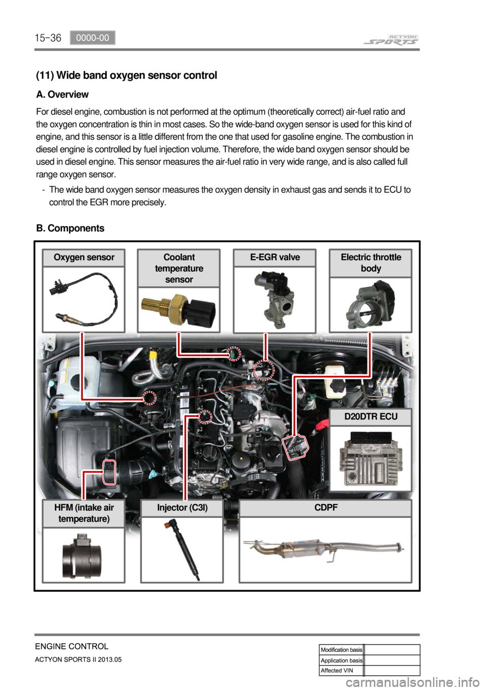
HFM (intake air
temperature)CDPF
Electric throttle
bodyCoolant
temperature
sensorOxygen sensor
Injector (C3I)
E-EGR valve
(11) Wide band oxygen sensor control
A. Overview
For diesel engine, combustion is not performed at the optimum (theoretically correct) air-fuel ratio and
the oxygen concentration is thin in most cases. So the wide-band oxygen sensor is used for this kind of
engine, and this sensor is a little different from the one that used for gasoline engine. The combustion in
diesel engine is controlled by fuel injection volume. Therefore, the wide band oxygen sensor should be
used in diesel engine. This sensor measures the air-fuel ratio in very wide range, and is also called full
range oxygen sensor.
The wide band oxygen sensor measures the oxygen density in exhaust gas and sends it to ECU to
control the EGR more precisely. -
B. Components
D20DTR ECU
Page 249 of 751

15-490000-00
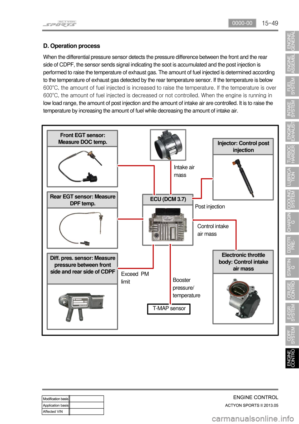
Diff. pres. sensor: Measure
pressure between front
side and rear side of CDPF
ECU (DCM 3.7)
Injector: Control post
injection
D. Operation process
When the differential pressure sensor detects the pressure difference between the front and the rear
side of CDPF, the sensor sends signal indicating the soot is accumulated and the post injection is
performed to raise the temperature of exhaust gas. The amount of fuel injected is determined according
to the temperature of exhaust gas detected by the rear temperature sensor. If the temperature is below
600°C, the amount of fuel injected is increased to raise the tem
perature. If the temperature is over
600°C, the amount of fuel injected is decreased or not controlled. When the engine is running in
low load range, the amount of post injection and the amount of intake air are controlled. It is to raise the
temperature by increasing the amount of fuel while decreasing the amount of intake air.
Front EGT sensor:
Measure DOC temp.
Rear EGT sensor: Measure
DPF temp.
Electronic throttle
body: Control intake
air mass
T-MAP sensor
Intake air
mass
Exceed PM
limitBooster
pressure/
temperaturePost injection
Control intake
air mass
Page 257 of 751

01-8
Front View ▶
NO. FUNCTION NO. FUNCTION
1 HFM Sensor 12 Intake Manifold
2 Intake Air Duct 13 Cylinder Head
3 Cylinder Head Cover 14 Exhaust Manifold
4 Ignition Coi 15 Dipstick Guide Tube and Gauge
5 Spark Plug Connector 16 Connecting Rod
6 Fuel Distributor 17 Crankshaft
7 Injector 18 Engine Mounting Bracket
8 Exhaust Camshaft 19 Starter
9 Intake Camshaft 20 Crankcase
10 Valve Tappet 21 Oil Pump Sprocket
11 Intake Valve 22 Oil Pan
NO. FUNCTION NO. FUNCTION
23 Camshaft Adjuster 29 Oil Pump Drive Chain
24 Oil Filler Cap 30 Oil Strainer
25 Engine Hanger Bracket 31 Oil Pump
26 Cooling Fan and Viscous Clutch 32 Ring Gear and Flywheel of Drive Plate
27 Oil Filter 33 Piston
28 Timing Chain
Side View ▶
Page 274 of 751

02-52211-06
1. FUEL SYSTEM
The function of the fuel metering system is to deliver the correct amount of fuel to the engine under all
operating conditions.
The fuel is delivered to the engine by the individual fuel injectors mounted into the intake manifold nea
r
each cylinder.
The main fuel control sensors are the Mass Air Flow (MAF) sensor and the oxygen (O2) sensors.
The MAF sensor monitors the mass flow of the air being drawn into the engine. An electrically heated
element is mounted in the intake air stream, where it is cooled by the flow of incoming air. Engine Control
Module (ECM) modulates the flow of heating current to maintain the temperature differential between the
heated film and the intake air at a constant level. The amount of heating current required to maintain the
temperature thus provides an index for the mass air flow. This
concept automatically compensates for variations in air density, as this is one of the factors that
determines the amount of warmth that the surrounding air absorbs from the heated element. MAF
sensor is located between the air filter and the throttle valve.
Under high fuel demands, the MAF sensor reads a high mass flow condition, such as wide open throttle.
The ECM uses this information to enrich the mixture, thus increasing the fuel injector on-time, to provide
the correct amount of fuel. When decelerating, the mass flow decreases. This mass flow change is
sensed by the MAF sensor and read by the ECM, which then decreases the fuel injector on-time due to
the low fuel demand conditions.
The O2 sensors are located in the exhaust pipe before catalytic converter. The O2 sensors indicate to
the ECM the amount of oxygen in the exhaust gas, and the ECM changes the air/fuel ratio to the engine
by controlling the fuel injectors. The best air/fuel ratio to minimize exhaust emissions is 14.7 to 1, which
allows the catalytic converter to operate most efficiently. Because
of the constant measuring and adjusting of the air/fuel ratio, the fuel injection system is called a "closed
loop" system.
The ECM uses voltage inputs from several sensors to determine how much fuel to provide to the engine.
The fuel is delivered under one of several conditions, called "modes".
Page 275 of 751

02-6
1) Starting Mode
When the ignition is turned ON, the ECM turns the fuel pump relay on for 1 second. The fuel pump then
builds fuel pressure. The ECM also checks the Engine Coolant Temperature (ECT) sensor and the
Throttle Position (TP) sensor and determines the proper air/fuel ratio for starting the engine. This ranges
from1.5 to 1 at -36 °C (-33 °F) coolant temperature to 14.7 to 1 at 94 °C (201 °F) coolant
temperature. The ECM controls the amountof fuel delivered in the starting mode by changing how long
the fuel injector is turned on and off. This is done by ''pulsing" the fuel injectors for very short times.
2) Run Mode
The run mode has two conditions called ''open loop" and ''closed loop".
3) Open Loop
When the engine is first started and it is above 690 rpm, the system goes into "open loop" operation. In
"open loop", the ECM ignores the signal from the HO2S and calculates the air/fuel ratio based on inputs
from the ECT sensor and the MAF sensor. The ECM stays in "open loop" until the following conditions
are met:
The O2 has a varying voltage output, showing that it is hot enough to operate properly.
The ECT sensor is above a specified temperature (22.5 °C).
A specific amount of time has elapsed after starting the engine. -
-
-
4) Closed Loop
The specific values for the above conditions vary with different engines and are stored in the
Electronically Erasable Programmable Read-Only Memory (EEPROM).
When these conditions are met, the system goes into "closed loop" operation. In "closed loop", the ECM
calculates the air/fuel ratio (fuel injector on- time) based on the signals from the O2 sensors. This allows
the air/fuel ratio to stay very close to 14.7 to 1.
5) Acceleration Mode
The ECM responds to rapid changes in throttle position and airflow and provides extra fuel.
6) Deceleration Mode
The ECM responds to changes in throttle position and airflow and reduces the amount of fuel. When
deceleration is very fast, the ECM can cut off fuel completely for short periods of time.
Page 276 of 751

02-72211-06
7) Battery Voltage Correction Mode
When battery voltage is low, the ECM can compensate for a weak spark delivered by the ignition
module by using the following methods:
Increasing the fuel injector pulse width.
Increasing the idle speed rpm.
Increasing the ignition dwell time. -
-
-
8) Fuel Cut-Off Mode
No fuel is delivered by the fuel injectors when the ignition is off. This prevents dieseling or engine runon.
Also, the fuel is not delivered if there are no reference pulses received from the CKP sensor. This
prevents flooding.
Page 404 of 751

04-218210-01
ABS Warning Light
This warning light comes on
when the ignition switch is turned
to "ON" position and should go
out if the system is normal.
The vehicle with ABS performs
self-diagnosis. During this
diagnosis, brake pedal vibration
and noise may be apparent
when the driving motors
discharges the hydraulic
pressure from the internal
hydraulic device.4WD IndicatorLow Fuel Level
Warnig Light
This warning light
comes on when the
fuel will soon be
exhausted. The time
it takes turn on,
however, varies
according to the
gradient of the
vehicle.
4WD HIGH Indicator
The lamp blinks momentarily during
the change of driving mode.
4WD LOW Indicator
The lamp blinks momentarily during
the change of driving mode.
4WD CHECK Warning Light
This indicates that there is something
wrong in the transfer case system.
(check the system) -
-
-
Auto Cruise Control
Indicator
Operating the cruise
control switch turns on
the indicator lamp to
indicate the cruise
control system is
activated.
Water Separator Warning Light
This lamp comes on to warn the driver of
water in the fuel tank which causes the loss
of engine power. When a certain amount of
water is accumulated, the lamp comes on
and a chime sounds.
Engine CHECK Warning Light
This warning light comes on when the
ignition switch is turned to "ON"
position and should go out if the
system related to engine control is
normal.
This comes on when different sensors
and devices related to engine control
are defective.
Winter Mode
Indicator
Pressing the "W" side of the
automatic transmission mode
selector switch switches the driving
mode to winter mode and turns on
the indicator lamp.
Use this mode to drive off smoothly
on icy and slippery roads.
Charge Warning Light
This warning light comes on when the
ignition switch is turned on and go off when
the engine is started.
If this light doesn't go off after engine starting,
it means there is a malfunction in the system.
Engine Hood Open Warning Light
When the engine hood is open, this light
comes on to inform the driver.
Hazard Indicator
This indicator blinks when the
hazard warning flashers are
switched on.
Page 458 of 751

01-12
2. FEATURES
Early Downshifts with Hard Braking and Skip Shifts ▶
When heavy braking is detected, the transmission downshifts early and skips gears to provide increased
engine braking to provide gear selection for tip-in.
Gear Hold on Uphill/Downhill ▶
If the accelerator pedal is released when travelling uphill, upshifts are prevented to reduce busyness on
grades. If the accelerator pedal is released when travelling downhill, upshifts are prevented to enhance
engine braking.
Soft Engagement when Shifting to “D” and “R” Position ▶
A soft engagement feature avoids harsh take up of drive when selecting Drive or Reverse. This is
achieved by limiting engine speed and engine torque which results in a rapid, but progressive
engagement of either Drive or Reverse when moving from the Park or Neutral positions. There is no
drive engagement prevention strategy implemented on the transmission system as there is sufficient
engine strategy to protect the system. However, reverse gear engagement is prevented until engine
speed is less than 1400 rpm and the accelerator pedal position is less than 12% and vehicle speed is
less than 10 km/h.
Converter Clutch Lock-Up In All Gears ▶
The transmission features converter clutch lock-up in all gears. This feature provides improved fuel
economy and vehicle performance. It also improves transmission cooling efficiency when towing heavy
loads at low speeds, e.g. in city driving or hill terrain.
Embeded Memory Module (EMM) ▶
The embedded memory module (EMM) is
matched to the transmission's valve bodies
during transmission assembly to ensure refined
shift quality. The EMM is integrated into the input
speed sensor which is mounted on the valve
body in the transmission. The EMM is used to
store data such as valve body calibration data
and valve body serial number. Upon installation,
the TCU will download the data from the EMM
and utilise this data in the operation of the
transmission.
1) Features