Page 38 of 751

02-70000-00
3. CHECK AND INSPECTION
1) Cylinder
(1) Compression pressure test
Specified value ▶
Compression ratio16.5 : 1
Test conditionat normal operating temperature (80˚C)
Compression pressureStandard32 bar
Minimum18 bar
Differential limit between cylindersMaximum 3 bar
The compression pressure test is to check the conditions of internal components (piston, piston ring,
intake and exhaust vale, cylinder head gasket). This test provides current engine operating status.
Before cranking the engine, make sure that the test wiring, tools and persons are keeping away
from moving components of engine (e.g., belt and cooling fan).
Park the vehicle on the level ground and apply the parking brake.
Do not allow anybody to be in front of the vehicle. -
-
-
Measurement ▶
<007e0088009900940047009b008f008c0047008c0095008e00900095008c0047009c00970047009b00960047009500960099009400880093004700960097008c00990088009b00900095008e0047009b008c00940097008c00990088009b009c0099008c00
47004f005f005700b6006a00500055>
Disconnect the fuel rail pressure sensor connector to cut off the fuel injection.
Remove the air cleaner duct and glow plugs. -
-
-
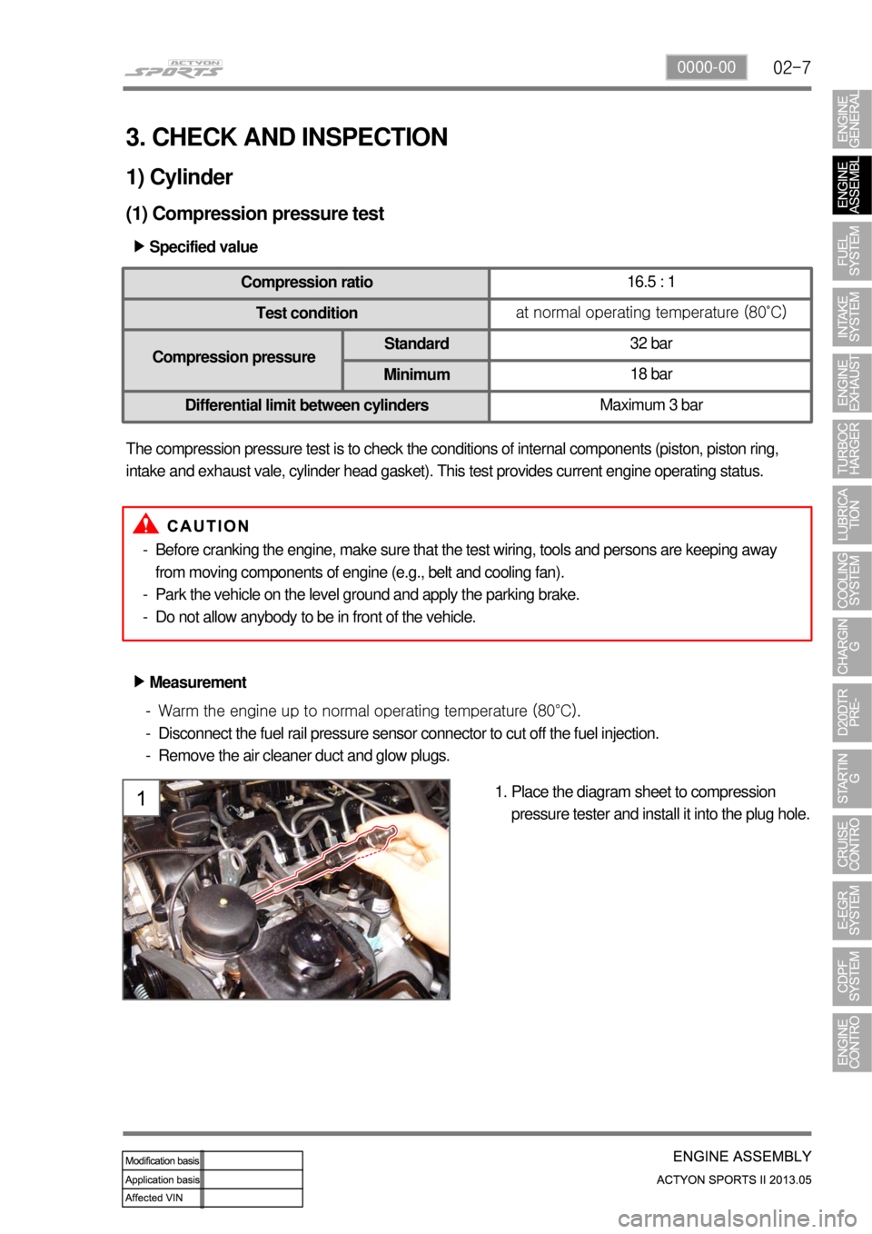
Place the diagram sheet to compression
pressure tester and install it into the plug hole. 1.
Page 59 of 751
02-28
Thickness markingEx: 1.3t
4) Cylinder Head Gasket
(1) Features
Sealing the cylinder gas pressure - Peak pressure: 190 bar
Minimizing the distortion of engine structure (cylinder head, block): \
profile stopper, backland
stopper
Material: MLS (Multi Layer Steel), Gasket (3 layers)
Thickness of gasket: 3 types (1.2 /1.3 /1.4 mm)
1.
2.
3.
4.
(2) Thickness of cylinder head gasket
There are three types of gasket to managing the compression ratio.
Piston protrusion
▶
Piston protrusion
Thickness
0.475 to 0.540 mm 1.2t
0.541 to 0.649 mm 1.3t
0.650 to 0.745 mm 1.4t
Page 67 of 751
02-36
Torque change curve of engine and drive shaft
Compression stroke Combustion stroke
Small changes from engine (k):
Damper increases the torque changes to clutchLarge changes from engine (j):
Damper decreases the torque changes to
transaxle by absorbing the impact
3) Operation
Compensating the irregular operation of engine: The secondary flywheel operates almost evenly so
does not cause gear noises
The mass of the primary flywheel is less than conventional flywheel so the engine irregularity
increases more (less pulsation absorbing effect).
Transaxle protection function: Reduces the torsional vibration to powertrain (transaxle) by reducing
the irregularity of engine. -
-
-
Page 111 of 751

04-10
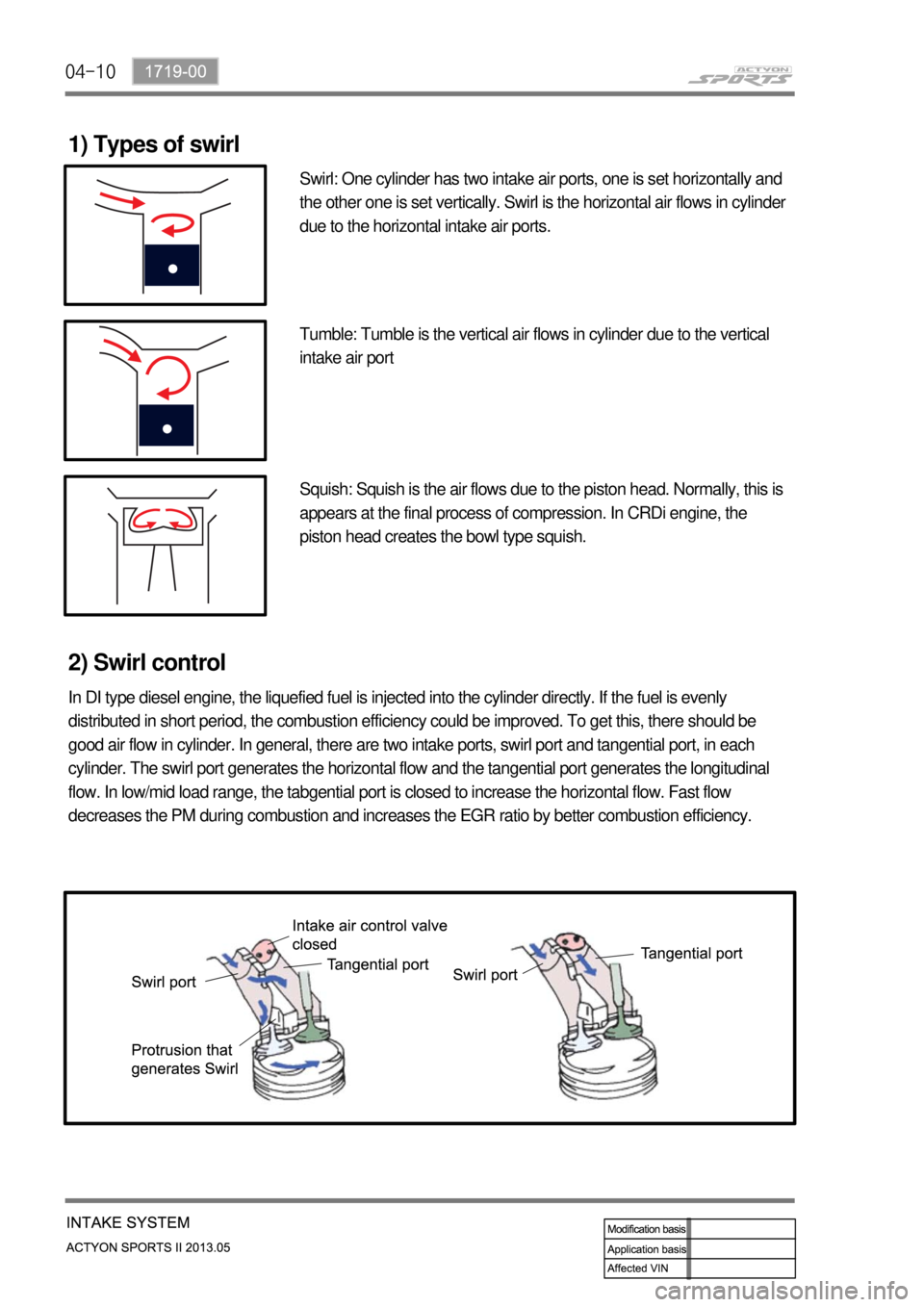
1) Types of swirl
Swirl: One cylinder has two intake air ports, one is set horizontally and
the other one is set vertically. Swirl is the horizontal air flows in cylinder
due to the horizontal intake air ports.
Tumble: Tumble is the vertical air flows in cylinder due to the vertical
intake air port
Squish: Squish is the air flows due to the piston head. Normally, this is
appears at the final process of compression. In CRDi engine, the
piston head creates the bowl type squish.
2) Swirl control
In DI type diesel engine, the liquefied fuel is injected into the cylinder directly. If the fuel is evenly
distributed in short period, the combustion efficiency could be improved. To get this, there should be
good air flow in cylinder. In general, there are two intake ports, swirl port and tangential port, in each
cylinder. The swirl port generates the horizontal flow and the tangential port generates the longitudinal
flow. In low/mid load range, the tabgential port is closed to increase the horizontal flow. Fast flow
decreases the PM during combustion and increases the EGR ratio by better combustion efficiency.
Page 626 of 751
11-24
2) DUMP (ESP is working) Mode
The pressure decreases just before the wheel speed drops and the wheels are locked.
The inlet valve closes and the outlet valve opens as in the ABS HECU and the oil is gathered at the low
pressure chamber while no additional oil is being supplied. Then the pump operates to allow fast oil
drainage. The shuttle valve and the separation valve do not operate while decompression.
Page 704 of 751
01-256810-01
6. A/C COOLING CYCLE
1) System Flow
"Compression -> Condensation -> Expansion -> Evaporation" -
2) Functions
(1) Compressor
Condition: Gas
Function: Circulates the refrigerant and increases the pressure and temperature for easier
evaporation. -
-
(2) Condenser
Condition: Gas/Liquid
Function: Cools and condenses the refrigerant by using ambient air to liquefy it under high pressure. -
-
(3) Receiver drier
Condition: Gas/Liquid
Function: Keeps the refrigerant free from moisture by separating/collecting the moisture from it. -
-
(4) Expansion valve
Condition: Liquid/Liquefied gas
Function: Performs adiabatic expansion and flow control for easier evaporation. -
-
(5) Evaporator
Condition: Liquefied gas/Gas
Function: Cools the air by absorbing the heat from the air around the evaporator. -
-
Page 705 of 751

01-26
3) Description for Each Cycle
(1) Compression
The evaporated refrigerant in the evaporator enters to the compressor. And the refrigerant gas is
compressed until it can be liquefied at ambient temperature.
Thus, the low refrigerant pressure is maintained so that the liquid refrigerant can be evaporated
actively at low temperature (around 0 ℃). -
-
(2) Condensation
The high pressure and high temperature gas (refrigerant) from the compressor is cooled down by the
fresh air entered into the condenser. Then, this gas is converted to liquid and collected in the receiver
drier.
The heat generated from the high pressure refrigerant is dissipated to the ambient air, and it is called
"heat of condensation".
The heat of condensation is the summation of the heat of vaporization (heat that the refrigerant
absorbs from the inside of the vehicle) and the calorific value converted from the amount of work
which is needed to compress. -
-
(3) Expansion
The liquid refrigerant lowers the pressure making its evaporation easily accomplished.
This process (lowering the pressure to the level at which evaporation easily takes place before the
liquid refrigerant is sent to the evaporator) is called
"Adiabatic Expansion".
During adiabatic expansion, the expansion valve lowers the pressure of the refrigerant and
determines the correct amount of refrigerant going into the air conditioning evaporator.
That is, the amount of heat, which is needed to stop the evaporation, is determined according to the
cooling load.
The expansion valve detects this and regulates the amount of the refrigerant exactly. -
-
(4) Evaporator
The refrigerant is converted from liquid to gas in the evaporator.
(The refrigerant in the form of fog in the evaporator is vaporized actively)
At this time the refrigerant, in the form of liquid, absorbs the heat in the air which is need for
evaporation (latent heat) and is cooled down. Then the blower blows the cooled air inside the vehicle
to lower the temperature.
There are liquid refrigerant from the expansion valve and evaporated refrigerant in the evaporator.
The evaporation temperature can be predicted from the evaporation pressure (i.e. relationship
between saturation pressure and saturation temperature).
It is important to keep the pressure inside the evaporator low, so that the refrigerant is evaporated at
low temperature to make sure the completely evaporated refrigerant is entered into the compressor. -
-
-
-
-