2013 SSANGYONG NEW ACTYON SPORTS lights
[x] Cancel search: lightsPage 95 of 751

03-18
3. CAUTIONS FOR DI ENGINE
1) Cautions for DI Engine
This chapter describes the cautions for DI engine equipped vehicle. This includes the water separation
from engine, warning lights, symptoms when engine malfunctioning, causes and actions.
DI Engine 1.
Comparatively conventional diesel engines, DI engine controls the fuel injection and timing electrically,
delivers high power and reduces less emission..
System Safety Mode 2.
When a severe failure has been occurred in a vehicle, the system safety mode is activated to protect the
system. It reduces the driving force, restricts the engine speed (rpm) and stops engine operation. Refer
to "Diagnosis" section in this manual.
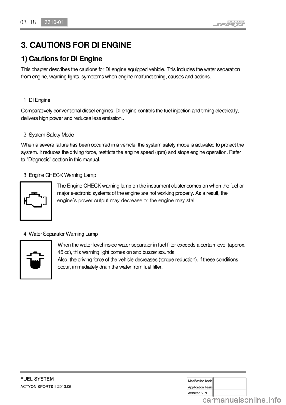
Engine CHECK Warning Lamp 3.
The Engine CHECK warning lamp on the instrument cluster comes on when the fuel or
major electronic systems of the engine are not working properly. As a result, the
<008c0095008e00900095008c02c5009a004700970096009e008c009900470096009c009b0097009c009b00470094008800a00047008b008c008a0099008c0088009a008c0047009600990047009b008f008c0047008c0095008e00900095008c0047009400
8800a00047009a009b0088009300930055>
Water Separator Warning Lamp 4.
When the water level inside water separator in fuel filter exceeds a certain level (approx.
45 cc), this warning light comes on and buzzer sounds.
Also, the driving force of the vehicle decreases (torque reduction). If these conditions
occur, immediately drain the water from fuel filter.
Page 172 of 751

12-4
2) Traffic Conditions for Using Cruise Control
Use the cruise control system only when the traffic is not jammed, driving on motorways or highways
where there is no sudden change in the driving condition due to traffic lights, pedestrian, etc.
Improper use of the cruise control could be dangerous.
- Do not use on winding roadsyy .
- Do not use in heavy traffic.
- Do not use on slippery, wet roads.
This could result in a loss of control, collision, and/or personal injuries.
Page 297 of 751

07-8
5) Jump Starting Procedure
Position the vehicle with the charged battery so that the jumper cables will reach from the charged
battery to the battery that requires charging.
Turn off the ignition, all the lights, and all the electrical loads in both vehicles.
Leave the hazard flasher on if jump starting where there may be other traffic and any other lights
needed for the work area.
Apply the parking brake firmly in both vehicles. 1.
2.
3.
4.
Shift an automatic transmission to PARK. 5.
Clamp one end of the first jumper cable to the positive terminal on the booster battery. Make sure it
does not touch any other metal parts.
Clamp the other end of the same cable to the positive terminal on the discharged battery. Never
connect the other end to the negative terminal of the discharged battery. 6.
7.
Clamp one end of the second cable to the negative terminal of the booster battery.
Make the final connection to a solid engine ground, such as the engine lift bracket at least 450
millimeters (18 inches) from the discharged battery.
Start the engine of the vehicle with the good battery.
Run the engine at a moderate speed for several minutes.
Then start the engine of the vehicle with the discharged battery.
Remove the jumper cables by reversing the above sequence exactly, removing the negative cable
from the vehicle with the discharged battery first.
While removing each clamp, take care that it does not touch any other metal while the other end
remains attached. 8.
9.
10.
11.
12.In order to avoid damaging the vehicle make sure the cables are not on or near pulleys, fans, or
other parts that will move when the engine starts.
In order to avoid injury, do not use cables that have loose or missing insulation.
Page 298 of 751

07-91452-01
6) Alternator
Alternators are equipped with internal regulators.
Unlike three-wire generators, the alternator may be used with only two connections: battery positive and
an "D+" terminal to the charge indicator lamp.
As with other charging systems, the charge indicator lamp lights when the ignition switch is turned to
RUN, and goes out when the engine is running.
If the charge idicator is on with the engine running, a charging system defect is indicated. This indicato
r
light will glow at full brilliance for several kinds of defects as well as when the system voltage is too high
or too low.
The regulator voltage setting varies with temperature and limits the system voltage by controlling roto
r
field current.
Achieve correct average field current for proper system voltage control by varying the on-off time. At high
speeds, the on-time may be 10 percent and the off-time 90 percent.
At low speeds, with high electrical loads, the on-time may be 90 percent and the off-time 10 percent.
7) Charging System
Generators use a new type of regulator that incorporates a diode trio.
A Delta stator, a rectifier bridge, and a rotor with slip rings and brushes are electrically similar
to earlier generators.
A conventional pulley and fan are used.
There is no test hole.
8) Starter
Wound field starter motors have pole pieces, arranged around the armature, which are energized by
wound field coils.
Enclosed shift lever cranking motors have the shift lever mechanism and the solenoid plunger enclosed
in the drive housing, protecting them from exposure to dirt, icy conditions, and splashes.
In the basic circuit, solenoid windings are energized when the switch is closed.
The resulting plunger and shift lever movement causes the pinion to engage the engine flywheel ring
gear.
The solenoid main contacts close. Cranking then takes place.
When the engine starts, pinion overrun protects the armature from excessive speed until the switch is
opened, at which time the return spring causes the pinion to disengage.
To prevent excessive overrun, the switch should be released immediately after the engine starts.
Page 403 of 751

04-20
3. WARNING LIGHTS AND INDICATORS
ESP OFF Indicator
This lamp comes on when
pressing the "ESP OFF" switch or
the ESP system is defective.
When the ESP system is
activated, this lamp blinks and a
chime sounds.
Immobilizer Indicator
This indicator comes on
when the ignition key is
communicating with the
engine control unit for
approx. 0.5 seconds.Glow Indicator
When the ignition key is turned
ON, this indicator lamp comes on
and the combustion chamber is
warmed up. In the vehicle
equipped with direct injection type
engine, this indicator may come
on very shortly or may not come
on.
Fog Lamp / Headlamp
High Beam Indicator
This lamp comes on when
the fog lamp or high beam
headlamp operates to
indicate the operating
status.Engine Oil Pressure Warning
Light
This lamp comes on if there is any
fault in the engine oil system and
goes off when a certain amount of
time has elapsed after turning ON
the ignition switch.
Door ajar warning
light
This light comes on
when a door or
tailgate is either
opened or not closed
completely.Brake warning light
This warning light comes on
and warning buzzer sounds
when the parking brake is
applied and/or the brake fluid
level is lower than specified
level.Seat belt warning lamp
The seat belt warning light comes on and
the seat belt warning chime sounds for 6
seconds when the ignition switch is
turned to "ON" position unless the
driver's seat belt is securely fastened.
This reminding operation stops when the
driver fastens the seat belt.
Engine Coolant Overheat
Warning Light
When the coolant temperature is
abnormally hot (over 120℃), this
warning light blinks and a warning
buzzer sounds at 1 Hz. (check
cooling system)
SSPS warning light
This warning light comes on when
the SSPS system is defective.
When this warning light comes
on, the steerability becomes
heavier.
Page 721 of 751

02-12
3. OPERATION PROCESS
The overall air bag operation process and its functions and roles are broadly explained in this block
diagram. This diagram summarizes and highlights the functions adopted by Ssangyoung Motors.
1) Air Bag System Block Diagram